Dental implantology based on osseointegration is among the most significant advances in dental science in the last 50 years. Imaging technology contributes to all stages of implant treatment, from presurgical site evaluation to postoperative assessment of integration, and long-term periodic evaluation of implant status. Various imaging modalities have been used for dental implant assessment in the different stages of implant treatment. These include intraoral radiography (film-based and digital), panoramic radiography, computed tomography, cone-beam computed tomography, and others. Selection of the specific imaging technique should be based on its suitability for providing the diagnostic information required by the implant team at different stages of treatment. This article reviews the applications of different imaging technologies and their diagnostic contribution to presurgical evaluation, treatment planning, and postoperative assessment of dental implants.
It is generally agreed that dental implantology based on osseointegration is among the most significant advances in dental science in the last 50 years. The success of implant surgery and restoration relies mostly on diagnostic imaging. This technology contributes to all stages of implant treatment, from presurgical site evaluation to postoperative assessment of integration, and long-term periodic evaluation of implant status.
Various imaging modalities have been used for dental implant assessment in the different stages of implant treatment. These include intraoral radiography (film-based and digital), panoramic radiography, computed tomography (CT), cone-beam computed tomography (CBCT), and others. Selection of the specific imaging technique should be based on its suitability for providing the diagnostic information required by the implant team (dentist, surgeon, radiologist) at different stages of treatment. This article reviews the applications of different imaging technologies and their diagnostic contribution to presurgical evaluation, treatment planning, and postoperative assessment of dental implants.
Presurgical implant site assessment is a challenging task. Apart from clinical evaluation, diagnostic imaging offers the sole method of noninvasive analysis of possible implant locations. To fully evaluate an edentulous or dentate site for implant treatment, several objectives must be met. These include the assessment of normal anatomic structures at, and in the vicinity of, sites of interest; detection of pathology proximal to the proposed sites; estimation of the quantity and quality of bone; and determination of possible implant insertion paths as indicated by the angulation of the alveolar ridge.
The anatomic structures proximal to possible implant sites include the mental foramen, mandibular canal, maxillary sinus, incisive canal, nasal fossa, and existing teeth, all of which may limit the placement of implants. Specific pathology may eliminate the incorporation of certain implant locations in the treatment plan. Root tips, impacted teeth, or other pathologic conditions must be corrected before or during implant surgery. The decision to place an implant should be based on the knowledge that the selected site contains structurally sound bone that can support the integration process. The chances of successful implantation are increased by more bone being available for anchorage and distribution of masticatory forces. Cortical bone is best suited to provide support for implants. Accurate estimates of the alveolar bone height and width are mandatory for selecting the appropriate implant size and determining the degree of angulation of the edentulous alveolar ridge. The assessment of the angulation of the alveolar ridge provides information regarding the proper insertion path of the fixture. The angulation of the alveolar bone represents the root trajectory in relation to the occlusal plane. Rarely does this bone angulation remain constant after loss of teeth. The pattern of resorption of the edentulous ridge may give rise to undercuts and should be taken into account during treatment planning and implant surgery.
Implant imaging techniques
Periapical Radiography
Periapical radiography produces a high-resolution planar image of a limited region of the jaws. Consequently, it may be used to evaluate the remaining teeth and residual maxillary or mandibular bone in the vertical and mesiodistal dimensions in a certain region of the oral cavity. Two intraoral projection techniques may be used for periapical radiography: the paralleling and bisecting-angle techniques. Although the goal of both techniques is to reduce image distortion, the paralleling technique is generally preferred, because the resultant image is less distorted. The main principle of the paralleling technique is that the radiographic film is positioned parallel to the long axis of the teeth and the central ray of the x-ray beam is directed perpendicular to the teeth and film. This orientation minimizes geometric distortion and may be achieved using film-holding devices. Furthermore, keeping the x-ray source fairly distant from the teeth results in additional reduction in the geometric distortion and increases definition of the radiographic image. The bisecting-angle technique is based on Cieszynski’s rule of isometry, which states that 2 triangles are equal when they have one common side and 2 equal angles. In dental radiography, the central ray of the x-ray beam is directed at right angles to an imaginary plane bisecting the angle formed by the long axis of the teeth and the radiographic film. The 2 right-angled triangles formed are equal and consequently have their hypotenuse sides (long axis of the teeth and film) equal. Consequently, the radiographic image of the teeth has the same length as the actual teeth.
Periapical radiography is a useful higher yield modality for ruling out disease in the area of interest and is of value in the identification of anatomic structures proximal to the implant site. Periapical radiography may be helpful in determining the approximate height of the alveolar bone, the distance of the proposed implant sites from key anatomic structures, and the quality of the recipient alveolar bone by means of bone density and trabecular pattern. Conversely, other authors contend that bone density measurements should not be attempted from periapical radiographs and that significant concerns regarding the amount of available mineral in the bone warrant other methods. Also, Misch considers periapical radiography to be of limited value in determining bone quantity because of the magnification. The imaging field with periapical radiography is restricted and its reproducibility is limited. Moreover, this modality is of no value in depicting the buccolingual width of the edentulous ridge. Periapical radiography is more often used for single-tooth implants in areas of abundant bone height and width. The use of periapical radiographs in the edentulous patients is limited.
Panoramic Radiography
The panoramic radiographic image is a curved slice of the maxilla and mandible of variable thickness, generated by a rotating x-ray source. This slice varies in thickness in the various panoramic machines and in the different areas of the oral cavity. Because of the specific image production principles, panoramic radiographs suffer from variable magnification, which is not the same in the vertical and horizontal planes. Equalization of the vertical and horizontal magnification is achieved only for a limited zone that lies within a curved plane called the central plain of the image layer or the focal trough. The focal trough is the zone in which structures demonstrate uniform magnification and appear more sharply on the radiograph. The focal trough shape and width vary from machine to machine. Structures that are positioned outside the image layer suffer distortion and magnification, the severity of which depend on the distance of the structures from the image layer. Panoramic radiography is a useful technique to evaluate the alveolar bone, the remaining teeth, and the location of neighboring anatomic structures (mandibular canal, maxillary sinus, nasal fossa) and to rule out the presence of other osseous pathology. It offers broader coverage of the maxillofacial region and allows comparison of contralateral structures. Panoramic radiographs are useful for the preliminary evaluation of the crestal bone height, bone quality and density, and cortical boundaries of the mandibular canal, maxillary sinus, and nasal fossa, provided that no positioning errors have occurred. The panoramic radiograph is a 2-dimensional (2-D) image of 3-dimensional (3-D) structures. Consequently, it does not demonstrate the buccal-lingual dimension of the maxillofacial structures, and therefore, it is inadequate for estimation of bone width. Moreover, it is a flattened, spread-out image of curved structures, resulting in considerable distortion of the structures and their relationship in space.
Panoramic radiography has a variable magnification that ranges from 10% to 30%. Sometimes, this varies in different areas within the same panoramic image ( Fig. 1 ). Also, image magnification is more variable when positioning errors are encountered. Misch states that panoramic radiography is misleading for alveolar bone height, because of magnification and the spatial relationship of the anatomic structures proximal to the area of interest being of little use.
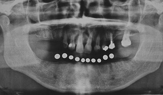
Panoramic radiography is, however, a fast, convenient, and readily available imaging modality, characteristics of which have made it popular with dental practitioners. Because of its popularity, clinicians have developed a means to compensate for recognized shortcomings and to correct for errors. Diagnostic splints incorporating metal markers with known dimensions enable the clinician to determine the magnification in the area of interest (see Fig. 1 ). Despite its popularity, panoramic radiography is inadequate as a sole means of surgical implant assessment because of the identified deficiencies. It may be used with other imaging modalities (ie, conventional tomography or CT) for a more adequate evaluation of the recipient site.
CT
CT is a digital imaging technique that allows the operator to generate sections of the tissues of interest by using a finely collimated rotating x-ray beam and a series of mathematical algorithms. The resulting images are free of blurring and overlapping shadows of neighboring structures.
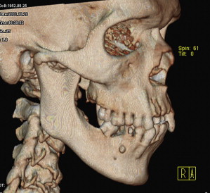
The CT scanner consists of a radiographic tube emitting a finely collimated beam directed to a series of scintillation detectors or ionizing chambers. The information collected by the detectors represents a composite of the absorption characteristics of all tissues and structures in the path of the x-rays. This information is transferred to the CT machine in which the data of the multiple projections are transformed into an image. The CT image is displayed as a matrix of individual blocks called voxels (volume elements), whereas the square of the image that represents each block on the screen is called a pixel (picture element). Each voxel and consequently the pixel by which it is displayed are characterized by a numerical value that reflects its x-ray attenuation features, which is mainly affected by the density of the tissue and its thickness (dimensions of the voxel). This is called the CT number. The computer assigns a specific shade of gray or density value to each CT number using a matrix of gray shades, which comprise the image. The primary advantage of CT is complete elimination of shadows of structures lying deep or superficial to the structures of interest. Moreover, because of its high-contrast resolution, CT can distinguish between tissues that differ by less than 1% in physical density. The density values of structures in the CT image are absolute and quantitative and can be used to differentiate tissues and characterize bone quality. The axial images of the CT study can be resynthesized along different planes by including only the image blocks along a specific plane. The operator may select voxels of certain coordinates only, to generate new images. The stored data are realigned to create images based on the diagnostic needs of the operator. This is called multiplanar imaging and allows the structures of interest to be viewed in different planes, depending on the specific diagnostic needs. CT can provide images with a 3-D perspective by using information derived from axial images of the structures of interest. The computer realigns the voxels of the axial scans in such a way that voxels are relocated in space in a position relative to one another. To create a 3-D effect, only the voxels that represent the surface of an object scanned are projected onto the monitor. This provides a solid appearance to the structures of interest. Also, the surface pixels are illuminated on screen as if a light source was present in front of the viewer. Thus, pixels that are close to the light source appear brighter than those further away. The more posteriorly the voxels are located, the less they are illuminated. This shading effect gives a 3-D appearance and depth to the scanned object, called surface rendering ( Fig. 2 ). In addition to dental implant assessment, 3-D reconstruction has been used in cases involving treatment of pathology and trauma and in craniofacial reconstructive surgery for the treatment of congenital anomalies.
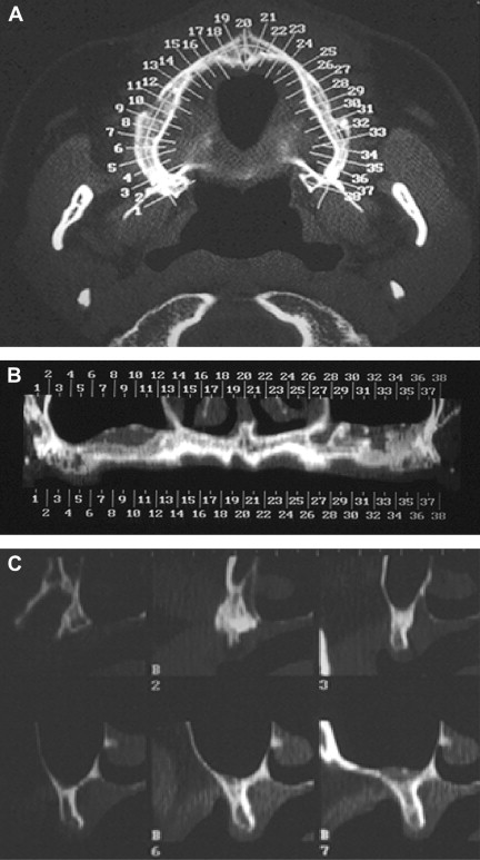
The development and widespread use of dental implants created the need for more specialized imaging protocols and multiplanar reformatting software programs that would consider the uniqueness of the maxillofacial region and the specific demands of implant surgery. Consequently, several proprietary programs that display multiple panoramic and cross-sectional images soon became available. Although the programs may differ from manufacturer to manufacturer, the following guidelines generally apply. After the acquisition of axial images, a curvilinear line is drawn on the representative axial image along the alveolar ridge (dentate and edentulous) in the midridge region. This line defines the plane and location of the panoramic reformatted images. The cross-sectional images are defined by multiple numbered lines that the software automatically places perpendicular to the curvilinear line ( Fig. 3 ). The space between the cross-sectional images can be varied. If a radiographic splint with opaque markers representing the proposed implant sites is used during the scan, the areas of interest are easily identified. Reformatted cross-sectional imaging with dental CT software results in images that meet almost all the requirements of presurgical implant site evaluation that were discussed earlier.
CBCT
The different imaging modalities discussed earlier provide answers to some of the diagnostic needs of implant therapy. Panoramic and intraoral radiography only provide 2-D information, not the 3-D information ideally required for implant planning. Also, their accuracy is strongly dependent on the skill and experience of the operator. CT has the potential to provide the required information with remarkable accuracy; however, it was only rarely used in dental medicine. Moreover, radiation exposure is fairly high, especially with older CT technology. The gap between traditional dental imaging modalities and CT was bridged with the introduction of CBCT.
CBCT uses a rotating x-ray source that generates a conically shaped beam, the width of which can be modified to fit variable-sized imaging volumes ranging from one-half of a dental arch to the entire head. The attenuated x-ray energy is acquired by a single detector with only one revolution around the patient’s head (in most CBCT systems). Similarly to CT, the diagnostic information is collected by means of x-ray attenuation from the voxels of the imaging volume (numerous small cubes within the imaging volume discussed earlier). These data are collected by a single detector and converted to shades of gray as is seen in CT. The primary difference between CT and CBCT in terms of the acquisition process is that the imaging data are acquired from the entire volume at once (one revolution) in CBCT, instead of stacks of slices (multiple revolutions) as occurs in CT.
The introduction of CBCT in dentistry almost 10 years ago is closely linked to a new paradigm in maxillofacial diagnosis called interactive diagnostic imaging. This has its foundations in the concept of multiplanar imaging/reformatting that was established in medical imaging (discussed earlier). CBCT allows for the reconstruction of various images in any plane, flat or curved, by selectively realigning the imaging data (voxels). This property is linked directly to the fundamentals of CBCT data acquisition, which can be considered volumetric. In essence, the information stored in a CBCT scan can be used to generate and display reformatted images of different types using portions or all of the data. The standard display mode is planar imaging (sequences of slices in different planes, axial, coronal, and sagittal, throughout the volume). If the user desires a panoramic image from the volumetric data, this can be accomplished by carefully selecting (with a cursor) an uninterrupted sequence of voxels along a curved plane in the maxilla or mandible. The resulting image is a reflection of the voxels in the selected plane. If the user selects the surface-only voxels to be displayed, then a 3-D view is produced (surface and volume rendering). Although multiplanar imaging is not a new concept in medical imaging, in most cases, the reconstructed images were recorded on static media, such as film or paper, without any potential for interaction. CBCT technology allowed interactive diagnosis, because the operator could now control the retrieval of diagnostic information. This has promoted interactive diagnosis, whereby the user can access much more information about each patient.
How does CBCT help?
Although CBCT has been used for preoperative and postoperative dental implant assessment, its contribution to the former is well documented in the literature. CBCT contributes to preimplant evaluation in various ways. The first and most important includes diagnostic considerations of the proposed implant site.
Preimplant Evaluation: Diagnostic Considerations
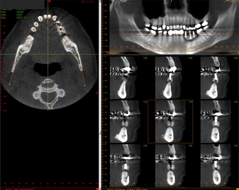
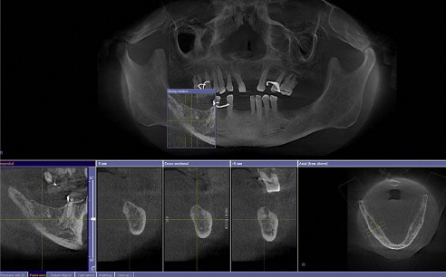
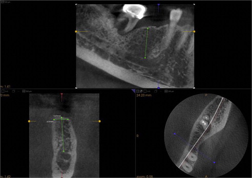
The clinician must know if an edentulous location is suitable for implant placement. Based on the concept of multiplanar reformatting described earlier, the proprietary software available with all CBCT scanners can provide multiple reconstructions, including sequential panoramic, cross-sectional, sagittal, and other type of images of the proposed implant sites or sites. For most scanners, these images are of variable thickness based on user preferences ( Figs. 4 and 5 ). These images represent the interaction in the CBCT machine. These reconstructions are the result of proper selection and handling of voxels in order for special images to be generated. Once the reformatted images are available, a series of interactive applications are at the user’s disposal, including measurement tools that provide alveolar bone height and width estimates ( Fig. 6 ). Estimates of alveolar bone angulation are also available. This information assists in selecting the proper fixture as relating to osseous dimensions and insertion path. One important question is the accuracy of these measurements, because implant surgeons rely on them in different ways. A CBCT image is similar to a conventional projectional image, in that it casts a magnified shadow of the structures of interest because of the geometry of the x-ray beam. However, CBCT manufacturers incorporate advanced mathematical algorithms that are applied after image acquisition, so that when the data are projected on screen, the images are already corrected for magnification. These measurements have been found to be very accurate for most CBCT scanners currently on the market. In fact, the estimated error in various diagnostic tests involving accuracy of measurements with different CBCT scanners was reported to be between 5% to 12%.
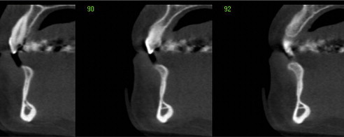
Dental implants are frequently placed in the jaws proximal to important anatomic structures that are to be preserved or respected during implant placement. The mandibular canals, mental foramina, fossae of the submandibular glands, lingual foramina, and neighboring teeth are some of these structures in the mandible. The nasal cavity, maxillary sinuses, nasopalatine canal, and neighboring teeth are some of the anatomic structures in the maxilla that may pose limitations to implant placement. Some of these structures are revealed with traditional dental images (panoramic, intraoral). However, the spatial complexity of some structures, (ie, the maxillary sinus, nasal cavity, and nasopalatine canal) limits the use of traditional dental images, even if they display the aforementioned structures. Anatomic complexity makes the use of sectional imaging a necessity. Cross-sectional images identify undercuts and anatomic concavities in the alveolar bone. Existing undercuts may be accentuated after tooth loss, when bone resorption occurs. Depending on their size, these findings may limit or compromise a potential implant site ( Fig. 7 ).
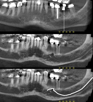
Compared with traditional imaging, advanced imaging, including CBCT, depicts other anatomic structures, such as the mandibular canal, in greater detail. Moreover, the simultaneous display of multiple reconstructed images in different planes (axial, coronal, sagittal, and cross-sectional) increases the chances of locating the mandibular canal, even if it was not identifiable in some of the images. To further assist the clinician in implant planning in the mandible, the path of the inferior alveolar nerve can be traced in the canal and evaluated in relation to the planned position of dental implants ( Fig. 8 ).