
Fig. 5.1.
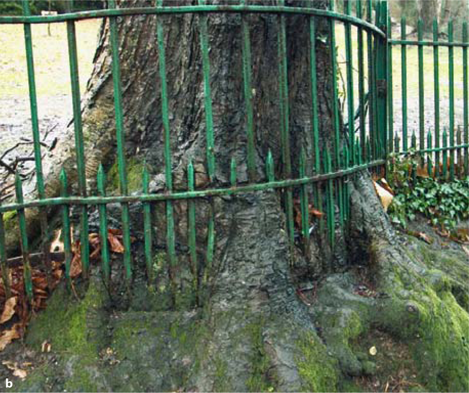
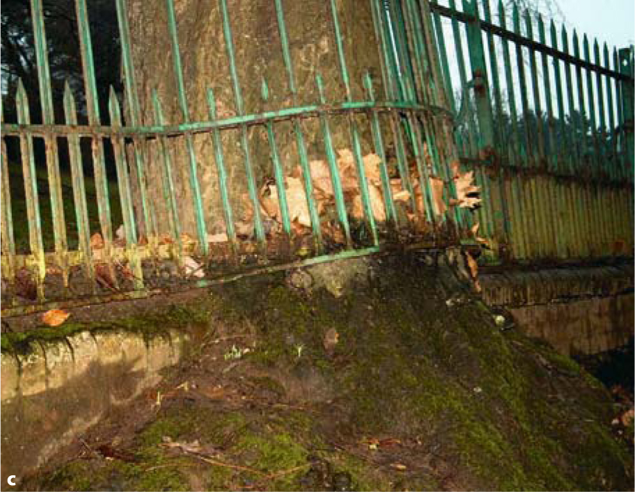
a When the horticulturist determined the design of this fence and the relative positions of the fence and the trees, he can hardly have been aware of the enormous strength and the possible extent of future growth. How could he otherwise place such – prospectively – massive trees right next to a delicate, skeletonized fence? However, both these units, the tree and the fence, were able to agree on a mutually acceptable level of peaceful coexistence and in this manner weather the decades. b Over the years, then, the tree that was condemned to grow and the fence that was condemned to withstand must have come to some kind of arrangement. Quite probably, it is now more the tree that holds the fence together than the fence’s own screws. A comparable result of peaceful spatial coexistence between living and dead matter is the objective of our enossal implantological work – whether we use crestal or basal implants. Within the contact areas, located inside the tree, the fence determines the positions and orientations of the macrotrajectories. That the fence (even if it had been made from titanium with the most miraculous surface) constitutes an additional stimulus for the tree to grow is something we would not suspect. But close observation of the different parts of the trunk emerging more fervently or more weakly lead one to assume that the 0–1 rule does hold for trees as well (see Chapter 9 for details of this aspect). c This tree was equally capable of bearing the burden of the years and the proximity of the fence, this time without any intimate connection between the two being necessary. A comparable result of peaceful spatial coexistence between living and dead matter can be the objective of our implantological work with subperiosteal implants or bent over vestibular BOI struts. d Peaceful coexistence must have existed here, too, at some point in the past. However, circumstances that probably were unrelated to the fact of coexistence itself have only afforded the living matter a shorter time span to survive
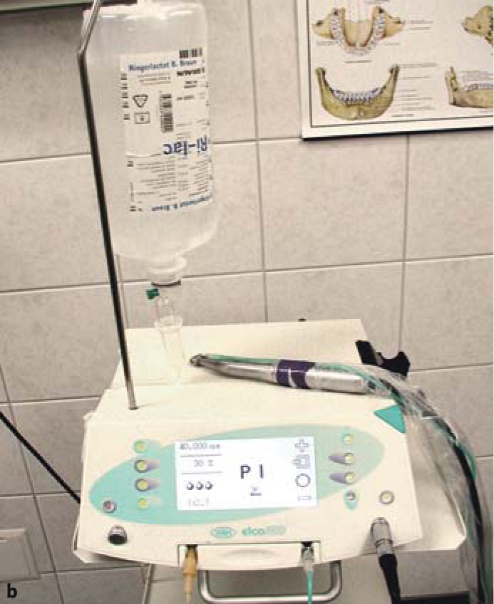
The preparation is usually performed with a turbine under profuse irrigation. Turbines offer the advantage of a low torque, i.e. they will even stop rotating when the surgeon uses excessive force. This precaution will avoid both heat-related injuries to the bone and premature wear of the cutting instruments. Helpful tools also include high-speed contra-angle handpieces and the ELCO system with on-board torque control recently introduced by W&H. The latter system is optimally used in conjunction with a contra-angle handpiece 1:2.7 at 20,000 or 40,000 rpm with the torque adjusted to 30%. High-speed contra-angle handpieces mounted to conventional dental units do not always offer torque adjustment. The cutters may sometimes bend in the hands of inexperienced surgeons, as even minor rotational imbalances from the bearing if the instrument will immediately deform the cutter when working at high torque. After all, the instrument reaches high speeds almost instantly. The speed of rotation as such, no matter how high it is, cannot inflict anywhere near the damage done by an excessive torque.
Once the vertical and lateral bone cuts have been created, the implant is inserted through a lateral access using carefully dosed hammer-style strokes. As the structural height in the basal plate area may vary depending on the exact design, it may be necessary to elongate the vertical cuts further to match the desired implant design. Overly forceful strokes that mainly hit the threaded pin should be avoided as they may induce plastic deformation along the pin and/or the web bars. If any parts of the implant are subjected to plastic deformation, these parts will be harder than the remaining non-deformed parts.
In this situation, areas of peak stress concentrations will develop right next to the deformation, carrying an increased risk of fracture if subjected to powerful cyclic loads. Not only may the vertical osteotomy be too narrow, but implant insertion may also be impeded if the horizontal osteotomy is too small. The height of the horizontal osteotomy is mainly selected in accordance with the thickness of the implant disk. Bone quality is, however, also a factor. In the posterior segment of the maxilla, it may be a good idea to create an undersized implant bed: some users like to insert 10-mm implants after using a 9-mm cutter for the preparation. This approach offers good primary stability of the implant. Note that the horizontal osteotomy must be advanced deep enough so bicortical anchorage is achieved.
In the mandible it may be necessary to take the reverse approach, namely to insert a 9-mm implant after preparing a 10-mm implant bed. Sometimes this is the only way to insert the implant without inflicting damage. As the central portion of the web bars is vertically reinforced compared to the peripheral portion at the ring, an adequate clamping effect is present between web bar and ring.
Sometimes the cutter may suddenly become jammed inside the bone and resist being removed. Such jamming is particularly common in the process of expanding horizontal slots in the distal mandible to 9 mm and is caused by plastic deformation of the jaw itself, which is subjected to strong flexion during mouth opening. Jaw structures will yield more readily to flexural forces while horizontal cutters are being used because they have been weakened by the previously established vertical cut already. The resultant plastic deformation stems from microcracks. Bone tissue permits crack formation while resisting crack propagation. Composites share this property as well, whereas glass behaves the other way round by permitting a certain degree of flexion but breaking along its entire surface once the point of no return has been reached, thus lacking the structural ability to prevent downright failure.
The extent to which the mandible is plastically deformed correlates with the degree to which the alveolar crest has been separated and the cut extended in a medial direction. The reader is referred to Chapter 11.1 for a detailed discussion of the biomechanical implications of weakened bone structures in the distal mandible for the vertical dimension. Some users prefer to insert BOI implants through a lingual access (particularly in the left mandible) if that area is well accessible and the cortical bone volume has been found to be greater on the vestibular aspect.
Slot gauges can be used to ascertain that the implant will smoothly glide into the slot. These aids are made of a titanium alloy featuring a polished surface. They can be cleaned and reused. Experienced users will not normally use a slot gauge, because there is no reason why the implant should not fit into the slot if the cutter could be advanced smoothly and the insertion procedure is not delayed. However the use of a slot gauge may be appropriate if the osteotomy was performed in a seriously resorbed area of the maxilla or mandible to avoid chipping of the fragile bone cover by having to use excessive force during the insertion procedure.
Whatever the case may be, the dentist has to make sure that the osteotomy extends into both cortical bone structures and that the implant can be smoothly advanced through the slot.
Non-resorbable grafting materials for the bone cuts are contra-indicated in the mandible because there is a risk that the material may migrate and give rise to chronic irritation of the mental nerve. Anyway, the stress-related regenerative capacity of this bone is so good that the slots will close spontaneously by native bone growth. Another convenient option is to introduce blood-derived autologous membranes with a calcium phosphate or calcium sulphate additive into the slots (Dohan et al. 2003; Blom et al. 1998). The osteotomy pathways may be obstructed by calcium sulphate or (tri-) calcium phosphate powder as substrate donors. Our impression has been that calcium sulphate is a highly effective mediator of soft tissue closure. Furthermore, it appears to reduce postoperative pain. These findings are subjective and remain to be confirmed in formal studies.
In the maxilla, any major bone defects may be filled with grafting materials (TCP, HA, autografts or allografts/xenografts) or covered with PRF. The important part is that the grafting material can be safely closed, so that it cannot become infected. Such sealing cannot possibly be achieved if the augmentation has been performed along the threaded pin. The option of performing augmentation procedures at sites of extraction that used to harbour periodontally compromised teeth or, for that matter, putrid processes should be considered with some scepticism because there is a high risk that the grafting material may become infected. If grafting is performed in these cases, the suppuration outside of the bone must be considered and a path for suppuration must be left. The implantation procedure as such is, of course, not contra-indicated in these situations nor is this preoperative situation an absolute contraindication for grafting in combination with the placement of BOI implants.
The thickness of the bone cuts depends on the implant design. EDXS-type single-disk implants feature a peripheral disk height of 0.8 mm, thus requiring the use of thicker cutters. The following cutters are available:
|
H 0.4 mm
|
H 0.6 mm
|
H 0.8 mm
|
|
|---|---|---|---|
|
ø 9 mm
|
×
|
×
|
×
|
|
ø 10 mm
|
×
|
×
|
×
|
|
ø 12 mm
|
×
|
×
|
|
|
ø 15 mm
|
×
|
While it may be possible to use an „undersized“ cutter in the maxilla to improve primary stability, a cutter of roughly the same dimensions as the implant is required in the mandible. Furthermore, it is recommended to use a 10-mm cutter for EDADS implants with a basal surface area of 9×14 mm to be inserted in the distal segment of the mandible. After all, the implantologist will never succeed in cutting a perfectly straight slot into the bone. Therefore, the implant cannot be advanced without jamming unless the slot is slightly wider in the first place (i.e. 10 mm instead of 9 mm).
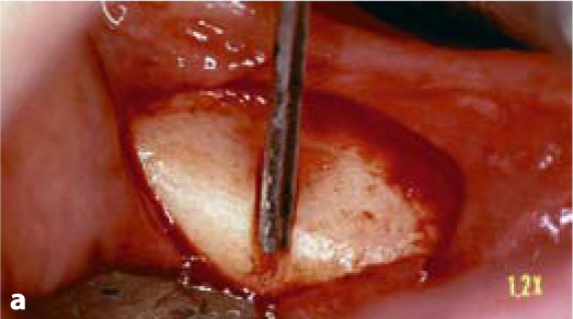
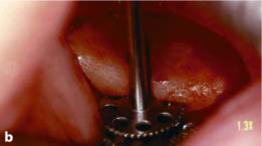
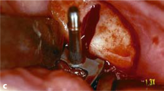
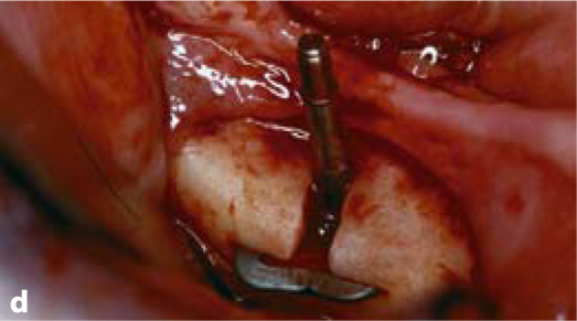
Fig. 5.2a-d.
The vertical osteotomy slot is cut first. It defines the direction, the departure point and the endpoint of insertion. Subsequently, a number of horizontal cutters with incremental diameters (starting with a 7-mm cutter) are applied. In maxillary structures and on the non-working side of the mandible, it is frequently possible to establish both the vertical and the horizontal slot at once by using a combination cutter (e.g. 10 mm). Once the slots have been completed, the implant can be inserted. It is recommended to use implants that are somewhat “oversized” in relation to the bone structure
5.3 Irrigation
Irrigation is usually necessary to protect the bone against overheating. The fact that such cooling must be provided during drilling procedures is not really open to debate. Albrektsson (1985) and Eriksson et al. (1982) demonstrated that a temperature of 47°C maintained over 1 min will give rise to significantly reduced bone growth in the vicinity of roughened implant surfaces. A temperature of 44°C maintained for up to 1 min, by contrast, does not induce demonstrable reductions in bone formation. Much more controversial is the issue whether it is possible to ensure adequate cooling deep inside the osteotomy cavity, especially when high-speed rotating instruments are used. While this question has been addressed in a number of excellent studies, the clinical relevance of these findings needs to be reappraised against the background of modern implant technology.
Scortecci and Doms (1987) demonstrated that heat does not accumulate in a significant way due to the water-air exchange resulting from correct irrigation with appropriate spray jet adjustment. In-vivo studies revealed that the temperature deep inside the osteotomy cavity rises to only around 26–28°C when irrigation is provided at 18°C (Scortecci 1988; Scortecci et al. 1990).
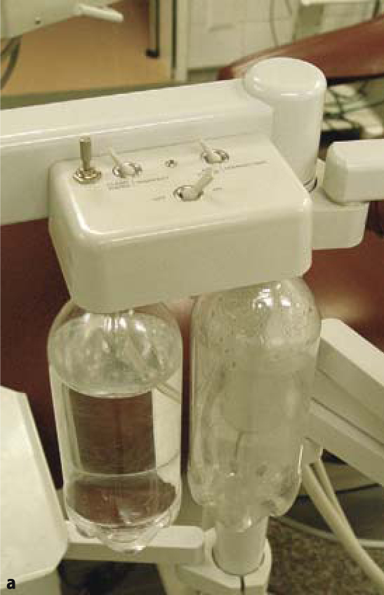
Figures 5.6–5.8 clearly demonstrate the usefulness of supplying both the turbine and the universal syringe with an appropriate cooling medium. The minor alterations required for this can be made to any dental unit. The „clean-water systems“ commonly used in the US can be connected to the delivery pipe and integrated into the water supply. Dentists who routinely insert implants will sooner or later use a dedicated chair for these procedures. There is actually no need to connect this chair to the tap water system.
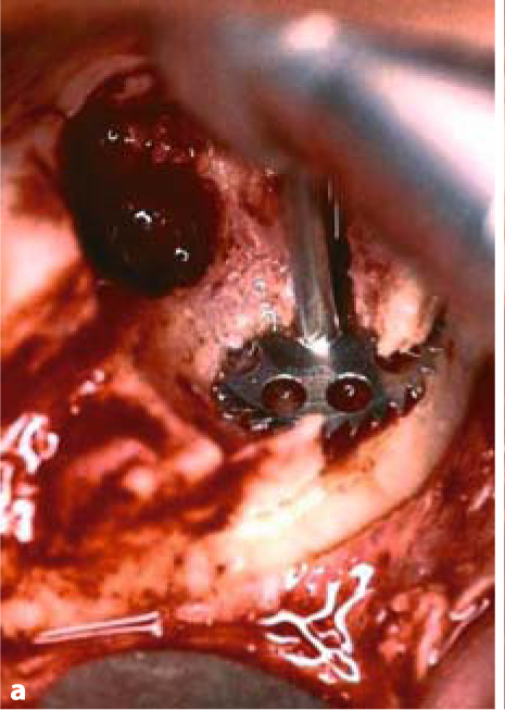
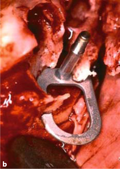
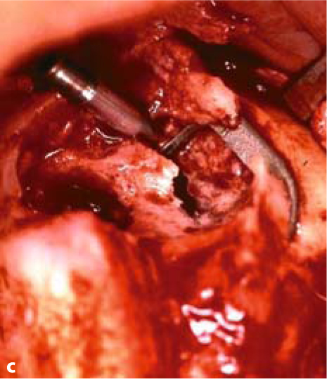
Fig. 5.3a–c.
BOI tuberosity implants are introduced parallel to the slot and then twisted inside the bone to adapt them optimally to the available jaw structure
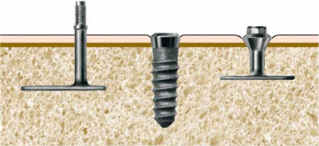
Fig. 5.4.
This diagram shows the correct heights of the prosthetic connectors. For BOI implants with external threading (E types), the region of the thread is positioned as far outside the mucosa as possible. By contrast, multi-unit screw implants are inserted into the bone such that only the polished parts of the thread are located in the mucosal area. BOI implants with internal threading (ID or IDO types), like screw implants, can be submerged more deeply than ED implants. The price to be paid, however, is the additional cleaning effort required. We tend to dispense with IDO implants in favour of ED implants in patients with discernibly poor oral hygiene, immuno-deficiencies or concomitant diseases that adversely affect the treatment prognosis, as well as in smokers
The practitioner will need to consider the following points:
-
Is the quality of the water from the dental unit adequate, or is a special irrigation fluid required? In most situations, a turbine and normal clean water will be all that is required to perform the entire surgical procedure.
-
The decision to use a special irrigation fluid raises the question whether the procedure can be performed with the regular dental unit or whether a separate surgical unit will be required.
-
The dentist must also weigh up the pros and cons for working with FG instruments (whether in the turbine or the high-speed angled handpiece) or with angled handpiece connections (i.e. the blue 1:1 handpiece).
-
The turbines must feature large rotor blades to offer the required power level. Also, the bearings of large-rotor turbines appear to be more rugged, which quickly pays off with large-diameter cutters. In our practice, we have come to use KAVO 650 and 650A as our preferred system and tend to consume three rotor heads in roughly 500 implant procedures a year.
We normally use sterile Ringer lactate as a cooling medium, which is stored in the refrigerator. Due to its composition, Ringer lactate is more benign to the bone than saline. After all, the bone harbours high concentrations of salts and proteins and is quickly drained of these substances when contact with liquids of lower osmolarity or altered composition is established.
To summarize, thanks to the availability of special surgical equipment and the option to retrofit all conventional dental units with clean-water systems, we are today in a position to conduct osteotomy procedures with high-speed rotating instruments in a clean and physiological manner (Ihde 2002). If the procedure is correctly handled, the bone will not be damaged beyond what is inevitable.
Not all bone areas are equally submissive to the cutting instruments used for osteotomy. Compressive areas (chewing side) offer the greatest and tensile areas (non-chewing side) the smallest resistance. This holds true for both jaws. Based on these parameters, the results of the preoperative functional analysis can be intraoperatively verified.
5.4 Configuration of the Load-Transmitting Surface and Threaded Pin
In the aesthetic zone, particularly of the maxilla, the threaded pins should be placed as far palatally as possible, so that the technician has freedom to optimally design the anterior dentition. To avoid restricting tongue movements, implants should not be placed to the anterior of the canines.
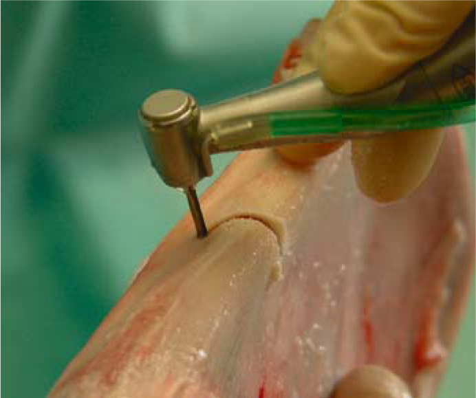
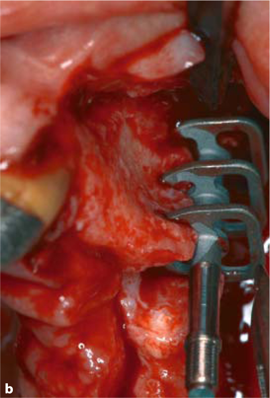
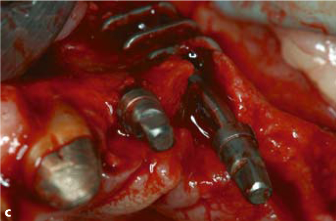
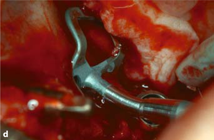
Fig. 5.5.
a Sometimes a curved slot is required to achieve the desired implant position and to utilize remote bone areas. b Insertion of a triple-disk BOI implant into a canine socket. c Insertion of a compression screw into the narrow ridge segment to the anterior of the triple-disk BOI implants. d BOI implants placed in the distal maxillary region often need to be pre-bent several times, so that the curvature of the threaded pin compensates for the palatal inclination of the slot. This will allow larger-diameter disks to be introduced. The vestibular flexion of the basal plate offers good adaptation to the lateral wall of the maxillary sinus (EDAS 10/14 G7). A pterygoid screw (STC 4.119) is already in place distally
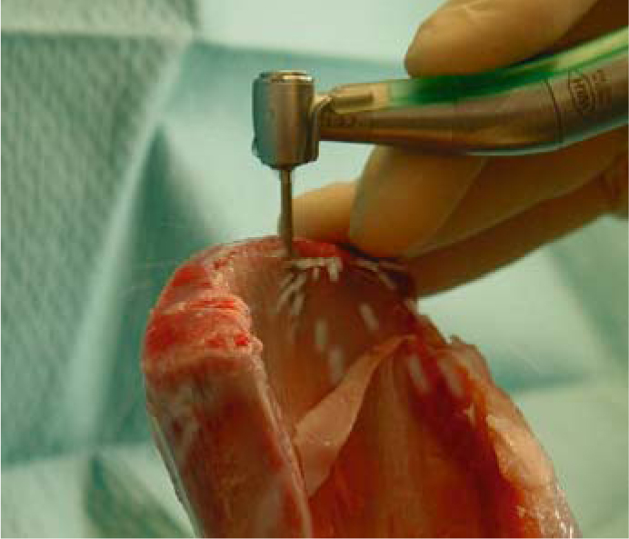
Fig. 5.6.
Even with the cutter fully inserted, enough irrigation fluid is driven through the osteotomy slot. The cooling effect is even better when an aerosol is used. The picture illustrates a test osteotomy performed on a pig scapula
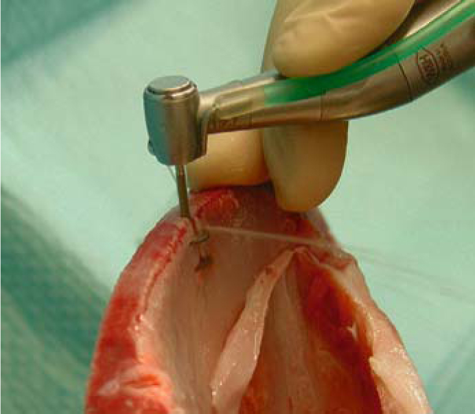
Fig. 5.7.
When twin cutters are used, the irrigation fluid will not normally reach beyond the crestal disk; the basal disk has to be irrigated separately
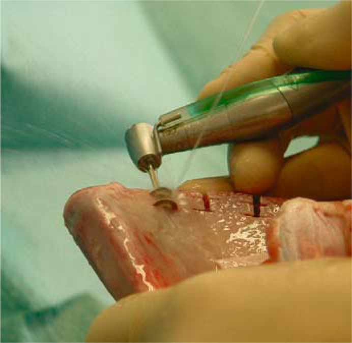
Fig. 5.8.
The basal disk of the cutter is cooled by an additional spray jet applied laterally through a universal syringe
With the implant designs available today, it is usually not necessary to place more than four implants per jaw. Abutments at the positions of the canines and second molars will usually suffice for strategically supported restorations. Additional implants may be indicated, however, in specific situations. Consider the following points:
-
Triple-disk implants may sometimes be a useful option in the anterior segment of the maxilla due to their osseoprotective effect.
-
If the immediate outcome of individual implants in terms of primary stability is uncertain, additional implants may improve the prognosis of the overall structure.
-
Treatment of severe dysfunction may involve a phase of high muscle resistance while the chewing function is being reconfigured. In this situation, it may actually be necessary to „sacrifice“ individual implants to create space for the chewing muscles. This presupposes that additional implants were inserted in the first place, or the entire structure will be in jeopardy. Alternatively, the dentist may choose to leave any residual teeth in place for the duration of the healing phase and extract them later before inserting the definitive restoration. Some users, however, prefer to use implants sparingly in the initial phase to retain a maximum of “virgin“ bone structure for any additional implant procedures down the road. This strategy may be advisable if the bone volume is generally low. Both strategies have specific advantages and disadvantages.
-
Some users insert five implants per jaw. In addition to the distal implant in both posterior segments, they use a total of three anterior implants, taking advantage of the anterior nasal spine in the maxilla and the heavily trajectorialized and mineralized anterior segment of the mandible.
-
The best results in the distal maxilla have been obtained with 12-mm implants. The width required to secure adequate support is also offered by EDAS 9/12 und EDAS 10/14.
-
The number of implants to be inserted in the maxilla also depends on the applicable disk diameters. The smaller the diameters, the greater the number of implants and/or disks per implant.
-
Bone elasticity in the mandible should not be unnecessarily reduced by using rigid implant designs. Large-diameter implants should be avoided at the distal abutment position in the mandible. If they have to be used after all, the disks should be inserted at a rather deep level. Four implants in the mandible will normally suffice as strategic abutments.
-
All relevant parameters such as the diameter, position and thickness of the disks as well as the number of implants and the number of disks per implant need to be matched.
-
If the patient wears a complete denture in the opposing jaw, the masticatory forces will be relatively low. It is therefore useful to keep the number of implants small.
-
Based on a total sample of 1,200 consecutive BOI implants, the probability of implant survival based on disk diameters can be summarized as in Table 5.1:
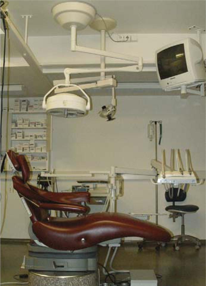 Fig.5.9.It takes intriguingly little to set up an ergonomically correct operatory. A spittoon is not required. The clean-water system is mounted behind the instrument tray on the transverse arm of the unit
Stay updated, free dental videos. Join our Telegram channel

VIDEdental - Online dental courses


