Taking into account the advantages of minimally invasive surgery, such as decreased morbidity, improved visualization and surgical precision, use as adjunctive teaching aid, and accurate documentation, endoscopy techniques have further progressed through scientific advancements. Apparent disadvantages, such as technique sensitivity and need for specialized training, have been improved. Scientific development includes enhancing various types of endoscopes, optics of endoscopic systems, and documentation of procedures.
The types of basic rigid arthroscopic optical systems include the rod-lens system by H.H. Hopkins of Reading, England, and the graded refractory index lens system (GRIN) by Nippon Sheet Glass Company, Osaka, Japan. Optical characteristics are composed of field of view and direction of view. Field of view is the angle drawn from the arthroscope tip to the extreme edge of field or object. Because the arthroscope is in a fluid medium, the field of view angle is approximately 40% less than when measured in air. The direction of view is the angle projected between the normal axis of the arthroscope and a line through the center of the image viewed through the arthroscope.
Optical parameters include the stigmatism of image, which is whether a point in the field is focused as a point in the apparent field. Also, distortion, which is a straight line in the object, is not necessarily reproduced as a straight line in the image. Chronic correction is the displacement of image axially as a function of wavelength or color, and the image may be different sizes as a function of color. Moreover, vignetting is the defect due to optical design, construction, or misalignment, which is caused by bending or displacement of the optical elements. Transmission is when each surface reflects some fraction of the light falling upon it, and each element has some absorption. Veiling glare is the image-forming light reflected by each surface that is in turn re-reflected in part by all surfaces preceding it in the system.
Documentation with photography and video adjuncts have made a major impact in allowing minimally invasive and endoscopic surgical techniques to evolve at an amazing rate. Consequently, oral and maxillofacial surgery has transcended the traditional surgical methods by incorporating endoscopic techniques as a pillar in future considerations and advancement.
Sialoendoscopy
The modern era of diagnosis of conditions involving salivary glands and their treatment starts with Charpy and Poirier in 1904, who performed the first sialographies with mercury, and Arcelin, who used bismuth in 1912 for the same procedure. Herman Kuttner (1870-1932), however, is credited with the most advancements in the development of anatomy, imagery, and surgery of salivary glands.
Imagery
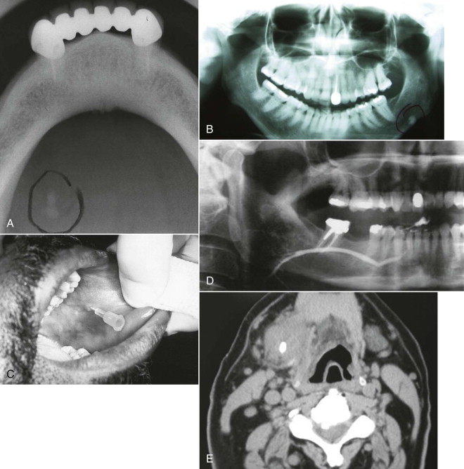
The multifactorial scope of imaging in the diagnosis and management of salivary gland obstruction consists of the confirmation of the clinical diagnosis of obstruction, exclusion of salivary gland pathology unrelated to obstruction (inflammatory and autoimmune conditions or tumors), differential diagnosis of obstruction (calculus, mucous plug, or stenosis), suitability for minimally invasive treatment, procedure planning, and monitoring of postoperative progress. Although plain film imaging ( Fig. 6-1, A and B ), sialography ( Fig. 6-1, C and D ), ultrasound, and scintigraphy contribute to the diagnosis and planning of surgical procedures, from the endoscopist’s perspective, computed tomography (CT) ( Fig. 6-1, E ) and magnetic resonance imaging (MRI) are the most relevant.

Imagery
The multifactorial scope of imaging in the diagnosis and management of salivary gland obstruction consists of the confirmation of the clinical diagnosis of obstruction, exclusion of salivary gland pathology unrelated to obstruction (inflammatory and autoimmune conditions or tumors), differential diagnosis of obstruction (calculus, mucous plug, or stenosis), suitability for minimally invasive treatment, procedure planning, and monitoring of postoperative progress. Although plain film imaging ( Fig. 6-1, A and B ), sialography ( Fig. 6-1, C and D ), ultrasound, and scintigraphy contribute to the diagnosis and planning of surgical procedures, from the endoscopist’s perspective, computed tomography (CT) ( Fig. 6-1, E ) and magnetic resonance imaging (MRI) are the most relevant.
Salivary Calculus (Sialolith or Stone)
Location and Number
Because most cases of sialadenitis have an obstructive etiology and most obstructions are caused by sialoliths, it is only natural to put more emphasis on the salivary calculus. Statistics show that between 63% and 94% of sialoliths occur in the submandibular gland. Within the submandibular gland, 9% of calculi are found in the gland parenchyma, 90% are in the duct, 60% are located in the hilum, and 30% are in the distal duct. In the parotid gland, 23% of stones are found in the parenchymal system, 13% in the hilum, and 64% in the ductal system. Multiple stones occur in 7% of parotid and 13% in submandibular sialolithiasis. Approximately 5% of patients will present with three or more stones. Parotid sialoliths are smaller, and in most cases, there is more than one. Average stone size in the parotid is between 6 and 8 mm; submandibular stones are slightly larger.
Structure and Composition of Sialoliths
As submandibular glands produce mostly mucous secretions, so the submandibular calculi are 8% inorganic and 94% radiopaque, hence denser and more calcium rich. The parotid gland, on the other hand, has a predominantly serous secretion. Therefore the parotid sialoliths are only 50% inorganic and only 43% radiopaque; they tend to be less dense and less calcium rich. The main minerals present in stones are calcium phosphate and carbonate in the form of hydroxyapatite, with various amounts of whitlockite in submandibular calculi and octacalcium phosphate in parotid calculi. The organic matrix of the sialolith represents 12% of the weight, 5% originating in insoluble proteins and 1% in lipids.
Pathophysiology
Though the exact cause of sialolithiasis remains somewhat elusive, there are a number of plausible theories, but none have been fully substantiated.
Mechanical Theory
Intermittent stasis secondary to hyposecretion, dehydration, strictures, convolutions, diverticuli, and other possible causes produces a shift in the mucoid element of saliva (hyperviscosity), forming a pseudogel. This gel provides the framework for deposition of salt and organic substances, eventually resulting in a stone.
Metabolic Theory and Phenomenon
Statherin, a calcium-binding protein, prevents primary precipitation of calcium phosphate in solution. Its presence creates a supersaturation of saliva with calcium and phosphate. Increases in the salivary bicarbonate level alter the calcium phosphate solubility and cause the precipitation of calcium and phosphate ions, triggering the calculus formation cascade. Acidic proline-rich proteins reduce secondary precipitation onto hard tissues. Hence a deficit of crystallization inhibitors will also contribute to or accelerate the phenomenon.
Inflammatory Theory
Bacterial ascent into the gland parenchyma causes an acute or chronic inflammatory response. The gland manifests a histologic pattern of chronic inflammation, resulting in hyposecretion or abnormal secretion of saliva and decreased salivary flow. Over time the condition becomes refractory to medical management.
Return to Function
Secretory function needs to be reestablished as soon as possible to restore viability of the gland. Absence or decreased secretory function will lead to recurrence of inflammation, mucous plug formation, or calculus formation. Human and animal studies have showed that glandular tissue secretory function can be regained even after extensive periods of obstruction and even atrophy. Restitutio ad integrum takes longer for the duct than for the gland. Full functional recovery takes between 6 and 24 months.
History of Sialoendoscopy
Sialoendoscopy is a rather recent development of the oral and maxillofacial surgery and otorhinolaryngology specialties. It started in 1990 when Konigsberger and then Gundlach performed the first successful endoscopy-assisted intracorporeal lithotripsy of sialoliths. Immediately afterward in 1991 Katz used a 0.8-mm flexible endoscope for the diagnosis of sialolithiasis as well as mechanical removal of calculi from the major salivary glands. In 1994 Arzoz introduced a 2.1-mm miniurethroscope with a working channel of 1 mm for use as an intracorporeal pneumoballistic lithotripter to fragment the calculus. Nahlieli published his 3-year experience with these techniques in 1997. In 2000 Marchal also reported on sialoendoscopic techniques. In 2001 Zenk reported his initial experiences with a new and highly flexible semirigid sialoendoscope with high quality imaging (6000 pixels). It had an external diameter of 1.1 mm and a working channel of 0.4 mm. In 2004 and 2006 Nahlieli and Nazarian published results of endoscopic treatment of juvenile and chronic recurrent parotitis, and radioactive iodine sialadenitis. , presented his experience with the treatment of idiopathic sialadenomegaly. McCain and Troulis published results of the first multicenter comprehensive study of these techniques in the United States in 2007.
Indications for Procedure
Sialoendoscopy fully justifies the coming of age of the endoscopic subspecialties and presents the same tremendous versatility. It is an excellent diagnostic technique for ductal and parenchymal strictures, occlusions, convolutions, and recurrent episodes of idiopathic sialadenomegaly. Interventional sialoendoscopy is an invaluable aid in the sialolithotomy of ductal calculi less than 6 mm in diameter, located as far as the gland hilum. It is also very useful for therapeutic submandibular or parotid lavage. The technique permits endoscopic examination of the ductal system immediately postsialolithotomy from the middle part of the ducts. And lastly, it can be used to successfully manage recurrent pathologic conditions in children.
Armamentarium
- •
Conic dilators. The dilators have been specifically designed to gently dilate the papilla without hemorrhage or trauma.
- •
Salivary probes. The probes are available in 12 sizes. The apex design permits atraumatic use of the instrument. The probes have a constant diameter along the working length. Manipulation should be gentle, limiting deep insertion and preventing ductal perforation and movements along false paths ( Fig. 6-2, A ).
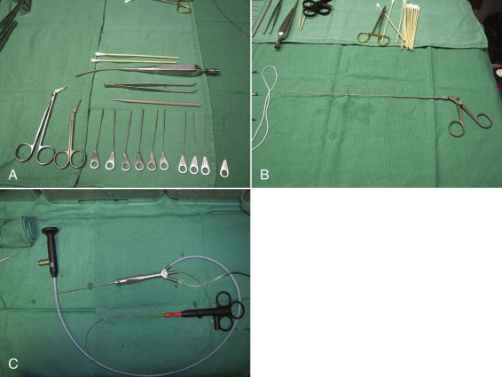
Fig. 6-2 A, Part of the sialoendoscopy armamentarium setup: 10 calibrated Marchal salivary probes (#0000-#6), angulated tenotomy scissors, papillotomy scissors, bougie, small Andrews suction-tip, and Q-tips. B, Endoscopic forceps. C, Holmium laser fiber protruding from the distal end of a Storz-Marchal cannula. - •
Hollow rigid bougies. The bougies allow blind dilation of gross stenosis of the main duct. The guide wire is inserted first under endoscopic control, traversing the stenotic process, and then the sialoendoscope is removed after marking the distance to the stenosis. The bougies are then inserted sequentially in increasing diameters.
- •
Forceps. This instrument measures 0.8 mm and can be used to retrieve small calculus fragments or to harvest biopsies in the ductal system ( Fig. 6-2, B ).
- •
Stone retrieval baskets. The baskets are available in three sizes, with three, four, or six wires each. Consistent with their denomination, they are used to engage and capture the stone for retrieval or deliver it close to the caruncula, where a papillotomy will facilitate retrieval.
- •
Sialoendoscopes. There are a variety of sialoendoscopes on the market, conveniently classified in two categories: multipurpose and all-in-one. In these authors’ experience, the current work-horse of sialoendoscopy is the Storz-Marchal 1.3 mm Universal, because it facilitates the diagnostic and interventional procedures on both Wharton and Stensen ducts. It is a three-channel endoscope with a working channel of 0.6 mm that permits advancement of both baskets and laser fibers ( Fig. 6-2, C ). It prevents insertion of balloon dilators or forceps.
Sialoendoscope Ports of Entry
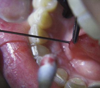
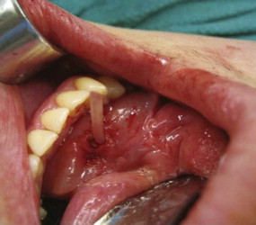
The natural access to the salivary ducts is the puncta salivaria ( Fig. 6-3 ), found in most instances at the center of the caruncula or papilla. They will require, in the majority of instances, dilation with lachrymal or ductal probes before insertion of the endoscope. Sometimes dilation of the punctum is impossible by conventional means, and a papillotomy with a CO 2 laser is performed immediately posterior to the orifice. If the papillotomy fails, then surgical dissection and exposure of the anterior portion of the duct via microsurgical technique together with longitudinal incision will facilitate the intraluminal insertion of the scope. Finally, if the stone is somewhat visible and palpable, a sialolithotomy incision will permit the intraluminal advancement of the endoscope after calculus retrieval.
This initial step of the procedure is by no means simple. The authors have had numerous opportunities to identify the factors contributing to difficult or unsuccessful duct dilation. Caruncula inflammation, papilla stenosis or calcification, previous gland and/or duct surgery with de novo or pseudoduct opening, preoperative administration of astringents or antisialagogues (parasympathomimetic medications), ductal orifice sphincter spasm, duct stenosis or fibrosis, abnormal duct convolutions, and duct occlusion or obstruction are all factors that can make ductal access and dilation practically impossible.
Ancient Roman wisdom states, “Errare humanum est. Perseverare diabolicum.” The free English translation is, “It is human to make mistakes. However, to persevere in the same mistake is diabolical.” Duct dilation and catheterization can be extremely frustrating at times. The surgeon has to patiently persevere in his attempts to find the punctum, and then dilate the duct, to the point of becoming diabolical. There is a steep learning curve in acquiring salivary duct stenting skills.
Surgical Technique
The surgical procedure can be performed with local anesthesia; however, for both patient and surgeon comfort, it should be done with general anesthesia. With the patient in a dorsal supine reflex position, general anesthesia is achieved via nasoendotracheal intubation. The surgeon should inform the anesthesia team that the patient is NOT to be given any parasympathomimetic drugs to prevent the antisialagogue effect associated with atropine, glycopyrrolate, and other drugs in this category. In our experience, general anesthetics potentiate hyposalivation even without the administration of such drugs. At this time, we are testing various general anesthesia techniques to rule out the medications with undesired effects toward the procedure, and to identify the ideal general anesthesia.
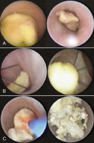
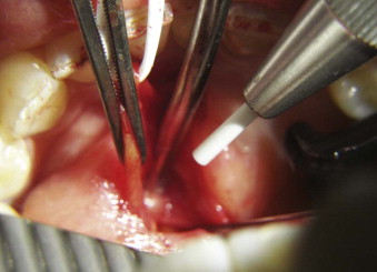
To expose the caruncula sublingualis, the ventral surface of the tongue must be elevated toward the palate. This can be performed by conventional retraction or by placement of one or two 2-0 silk sutures paramedian through the lingual apex. The papilla is very gently manipulated and instrumented. Our preference is to apprehend with dental pick-ups (“cotton pliers”). No suction should be applied to the papilla, rather saliva should be blotted with Q-tips. After locating the punctum, progressive dilation of the duct is performed with salivary probes of increasing diameter. We favor the calibrated Marchal salivary probes. A duct dilated to a size #3 or #4 probe should accommodate the Storz-Marchal 1.3-mm scope. The scope is then advanced as far proximally into the duct as permitted (to the obstruction or into the gland hilum) ( Fig. 6-4, A ).
Notwithstanding the apparent simplicity and straightforwardness of the technique, extensive elaborative remarks could be made on the subject. The paramount summation is that sialoendoscopy, whether diagnostic or interventional, adheres to the basic principles of endoscopy, where the optical cavity is maintained with closed system irrigation and the navigation is facilitated by duct straightening. The alignment of the duct over the cannula is a “pull-out” maneuver similar to the apprehension of the caruncula with angled pick-ups (see Fig. 6-3 ) to facilitate dilator insertion.
The versatility of this procedure cannot be overemphasized. Calculi of small diameter can be grasped with forceps, wire baskets ( Fig. 6-4, B ), or graspers, instruments that are manipulated through the working cannula of the endoscope. The obstructive mucous plug or sialolith can be dislodged by gentle retraction and removal of the endoscope. In many situations (calculus of diameter >6 mm) a papillotomy will be necessary for retrieval, because the orifice sphincter will not dilate past 3 to 4 mm in most cases. If the sialolith is too large to be advanced distally toward the duct emergence, it can be morcelized with forceps, then fragments can be removed under irrigation. This particular approach has become quite popular for fixed or impacted calculi. Another approach that we particularly favor is fragmentation of calculi with the holmium laser before removal ( Fig. 6-4, C ). The technique can also be combined with intracorporeal and extracorporeal lithotripsy.
Duct stenting is performed at the end of most sialoendoscopies (invasive or noninvasive) and sialoendoscopically assisted surgeries on salivary glands or ducts. The preferred method is to use 4-0/5-0 proline or other nonresorbable suture to secure a polyethylene tube fashioned out of a butterfly catheter at the papilla, de novo orifice, or duct opening ( Fig. 6-5 ). The stent will usually correct most unfavorable angles and convolutions of the Wharton duct around the lingual nerve and the mylohyoid muscle (one of the main causes of obstruction supporting the mechanical theory). It also prevents ductal lumen obstruction by postoperative edema. The stent facilitates physiologic lavage of calculus fragments by saliva. The longer the stent remains in place (the authors remove it at 4 weeks postoperative), the less likely it is that postoperative duct stenosis occurs. Finally, it prevents the extravasation phenomenon (with subsequent ranula formation) and decreases the possibility of recurrence of sialolithiasis.
Surgical Technique for Endoscopic Intraoral Sialolithotomy With or Without Sialoductoplasty
As previously mentioned in this chapter, frequently the size of the stone will prevent endoscopic retrieval, notwithstanding capture of the sialolith with endoscopic basket or graspers. However, the sialoductoplasty ( Fig. 6-6 ) becomes an easier, faster, and much more precise procedure. In other instances, the obstruction removal is not amenable to or fails pure endoscopic techniques, mostly because of a stenosed duct.
The first steps of the procedure are identical to the standard endoscopic approach. The endoscope is inserted in the duct to locate the obstruction, lavage, and dislodge the calculus from the ductal attachment, if present. The duct is then dissected and isolated from the surrounding tissues to the level of the first mandibular molar for the submandibular gland or the right angle deviation over the masseter for the parotid gland. Next, a longitudinal ductotomy with a CO 2 laser over a salivary probe or endoscope will expose the obstruction. The submandibular gland is impinged cranially, toward the oral cavity, with manual pressure from the submandibular region. With fine hemostats, the duct is extended anteriorly (with very light tension) at the same time. After the obstruction is removed, the proximal duct is explored endoscopically to rule out the presence of additional calculi or fragments, and the ductal system is lavaged as far as the hilum.
Discussion
The authors’ data are supported by 7 years’ experience with sialoendoscopy and sialoendoscopically assisted procedures at Miami Baptist Hospital. They feel that presenting a summary of results is extremely relevant for the implementation of these techniques.
Salivary duct dilation and navigation was performed in 100 out of 104 cases (97%). Sialolith retrieval or emulsification was successful in 64 out of 80 attempts (84%). Strictures or mucous plugs were managed in all attempted cases (100%). Ductal stenting was achieved in 77 out of 85 cases attempted (87%). In all, 87 out of 99 cases with chronic sialadenitis achieved symptomatic relief. At the time this chapter was written, 22 out of 104 cases were deemed failures. Six patients underwent subsequent salivary gland removal (five submandibular and one parotid). Nine patients are asymptomatic and do not desire further intervention. One patient’s symptoms resolved with de novo sialoendoscopy and sialolithotomy. Six patients were subsequently treated with transoral sialoductoplasty.
The average sialolith diameter in the cases deemed failures was 1.1 ± 0.4 cm, determined by preoperative CT or radiograph. Twenty-one percent of the ducts could not be explored to the hilum following removal of the obstruction, secondary to strictures and adhesions. In 15% of cases, some extravasation of the irrigating fluid elevated the floor of the mouth. No patients required emergency airway management. In 24% of situations the sialoendoscopy was aborted for the open procedure because the obstruction was not visible or could not be reached with the endoscope. Intraluminal navigation was restricted by convolutions, strictures, mucous plugs, and adhesions. In 27% of the cases, the duct emergence had to be opened via papillotomy with a No. 11 scalpel, both to cannulate the duct and to accommodate passage of large stones.
The authors have had an overall success rate of 28% for pure intraluminal stone retrieval without open intervention. In 62% of patients, open intervention was required and sharp and blunt dissection was used to enter the duct and remove the obstacle under direct vision. The sialolith was visualized near the hilum of the gland, but persistently rolled in and out of the gland, resulting in no stone retrieval by either method (intraluminal or open) in 10% of situations. One patient experienced a transient lingual nerve paresthesia. Another had to remain intubated overnight for observation secondary to extravasation phenomenon.
Although the learning curve is rather steep, endoscopic access to the salivary ductal system for management of sialolithiasis and strictures is feasible. Sialoendoscopy permits a minimally invasive surgical procedure that reduces the unnecessary removal of histologically functional glands and decreases the risk of facial nerve paresis.
Clinical Endoscopic Observations
The authors’ clinical endoscopic experience and results concur with those of Nahlieli and Marchal. The following are a few pertinent facts that were apparent during sialoendoscopy that the authors continue to observe and research.
There has been debate over ductal peristalsis, mostly inspired by the spontaneous passage of rather large calculi before any therapeutic maneuvers. Peristalsis could force calculi out of the duct. But increased pressure caused by saliva accumulation proximal to the obstruction, secondary to intraparenchymal hypertension, could also be responsible for dislodging the sialolith from the duct. Possibly a combination of both mechanisms underlie spontaneous passage. However, the presence of smooth muscle fibers within the ductal wall, pseudosphincters beginning at the caruncula for the Wharton duct, respectively adjacent to the ramification inside the Stensen duct, has been documented.
The phenomenon of sialolith impaction was noted to occur distal to the bifurcation in the Wharton duct and masseteric curvature in the Stensen duct. It makes sense to postulate that in cases of long-standing ductal sialolith impaction, a ductal diverticulum will form, which makes calculus fragments or secondary calculi retrieval very difficult. Depending on the amount of muscle fibers in the ductal adventitia, this may not resolve after obstruction removal or disimpaction, or both. In one case of reentry sialoendoscopy, the sialolith was documented by imagery, located via endoscope, but found completely encased in the ductal wall. It was not retrieved because it was very close to the lingual nerve and also because duct stenting had reestablished patency and flow.
Rather infrequently found, with a 2 : 1 ratio in Stensen and Wharton ducts, ductal polyps obstruct salivary flow. Sialoendoscopy is the only consistent diagnostic method. Polyps may be removed or excised with forceps or baskets. The ratio for ductal strictures in Wharton and Stensen ducts is 2 : 1, and for convolutions, the ratio is 3.5 : 1. Other endoscopist-clinicians have mentioned highly infrequent occurrences, such as foreign bodies (hair or plant fragments) and anatomic malformations (hilar pseudopelvic malformation), that we have not yet encountered.
The Bartholin duct or sublingual duct is infrequently found emerging up to 5 mm distal to papilla, in the anterior portion of the Wharton duct. A consistent finding in chronic sialadenitis or long-standing sialolithiasis is the ecchymotic, angiopenic, and matted appearance of the ductal mucosa.
Endoscopically Assisted Orbital Floor Fracture Repair
Anatomy Abbreviated
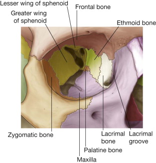
The human orbit is a quadrangular pyramid with the peak at the orbital apex, averaging a volume of 30 mL. in the adult, with the globe occupying 7 mL. Maintaining and restoring orbital volume is critical for globe position and visual acuity. The seven osseous components of the orbit are the maxilla, zygomatic, frontal, ethmoid (os planum), lacrimal, palatine, and sphenoid ( Fig. 6-7 ). The maxilla, zygomatic, and palatine form the adult orbital floor. The orbital floor is the shortest of all the walls; 35 to 40 mm does not reach the orbital apex and terminates at the posterior margin of the maxillary sinus. The infraorbital sulcus, canal, and foramen are continuous and tunnel through the maxilla, encasing the terminal maxillary branch of the trigeminal nerve, the infraorbital artery, and infraorbital vein.
Mechanisms and Configuration of Orbital Floor Fractures
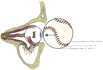
Fractures of the anterior and medial thirds of the orbital floor and medial wall are common because of their thin walls and lack of support. The increased intraorbital pressure is relieved by traumatic expansion of the walls with herniation of orbital contents into the maxillary sinus, the ethmoid air cells, or both.
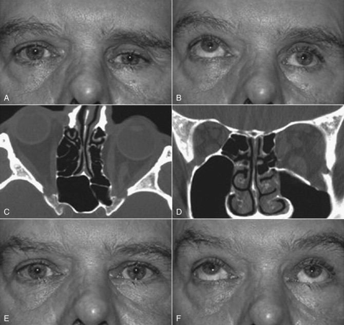
Linear internal orbital fractures maintain periosteal attachments and rarely herniate orbital contents; however, they result in an increase in orbital volume, hypoglobus, and enophthalmos. Blow-out fractures are the most common. They are 2 cm or less in diameter and most often involve the anterior and medial floor ( Fig. 6-8 ). These as well as the two-wall and complex fractures, or those extending to the posterior orbit, are amenable to pure endoscopic repair. However, the endoscopic-assisted open reduction and internal fixation (ORIF) remains the preferred method for the more complex fractures and those extending to the posterior orbit.
Presentation of Orbital Floor Fractures
The inherent problems with orbital floor fractures are hypoglobus, enophthalmos, diplopia (secondary to inferior rectus, orbital tissue entrapment, or both), restricted ocular range of motion, orbital emphysema (from communication with the maxillary sinus) ( Fig. 6-9 ), orbital hemorrhage with the risk of compressive optic neuropathy, globe rupture, hyphema, retinal edema, decreased visual acuity, or even amaurosis.
Surgical Technique
There are four classic approaches to the orbital floor: subciliary, transconjunctival, midtarsal, and transantral. In the traditional periorbital approaches, the posterior margin of the orbital floor defect is often difficult to visualize. The unassisted, conventional techniques require significant manipulation of the orbital tissues, result in inflammation, and increase the risk of ectropion or entropion. The transantral approach can be performed in a transmaxillary or transnasal fashion. These authors favor the transantral/transmaxillary approach.
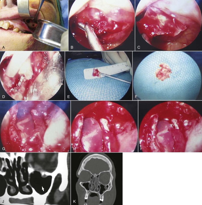
With the patient under general anesthesia via oral endotracheal intubation, the forced duction test is performed. Access to the lateral antral wall is achieved via a modified Caldwell-Luc incision. The lateral antrostomy is performed next with the positioning of two portals, each 6 to 7 mm in diameter, with the posterior osteotomy at the buttress area ( Fig. 6-10, A ). The antrum acts as a natural optical cavity. A 30-degree endoscope, 4 mm in diameter (Karl Storz, Tuttlingen, Germany) with a xenon light source is preferred; however, a 0-, 45-, or 70-degree scope may also be used. The endoscope is inserted through one antrostomy (the vision portal), while instruments are manipulated through the working portal. The fracture site is visualized, inspected, then demucosalized. Each shelf is carefully dissected, and prolapsed orbital fat is repositioned cranially into the orbit. All margins of the fracture are identified ( Fig. 6-10, B and C ). All sharp osseous fragments are removed or conformed ( Fig. 6-10, D and E ). The fracture is reduced and de novo forced duction testing is performed. Pulse testing is performed under endoscopic vision. Care is taken when manipulating the intraorbital contents from the antrum to avoid impingement of the musculature, periorbita, and optic nerve. The infraorbital nerve and inferior rectus muscle are identified. For the operative situations where orbital contents continue to herniate and the orbital volume requires additional support, a Silastic implant is trimmed, adapted, and stabilized on the orbital floor ( Fig. 6-10, F to I ) so that both orbital volume and ocular globe function are restored. The forced duction and pulse tests are repeated under transantral endoscope inspection. The incision is usually closed with a tight water seal and resorbable interrupted sutures. The postoperative CT will confirm adequate floor position ( Fig. 6-10, J and K ). The patient receives sinus precaution instructions.
Based on the intraoperative findings, the surgeon is always prepared to access the orbital floor from a periorbital approach. Possibly one of the greatest advantages of the endoscopic approach is the ease of converting to an endoscopically assisted open approach should the necessity arise.
Some other advantages of endoscopic surgery are direct vision and evaluation of the surgical field, smaller incisions, precise reductions and repairs, and decreased postoperative morbidity, preventing the relatively high complication rate of the transcutaneous and transconjunctival approaches, including poor cosmesis. From the patient perspective, there is no question about the choice, because the advantages by far outweigh the disadvantages. The only disadvantages are increased surgery time, need for advanced surgical skills only achievable through a longer learning curve, and additional costs and manpower. In addition to those just mentioned, there are additional advantages of the endoscopic open reduction with implants for the orbital floor fractures. The displaced orbital floor acts as a scaffold for fracture reduction, maintained by the implant from the antral side. There is no additional intraorbital foreign body, preventing infraorbital interference with the ocular muscles and the infraorbital nerve. The reduction is purely anatomic. This is the only approach, giving the surgeon the ability to ascertain the forced duction test (via endoscope) from an inferosuperior perspective, thus observing the inferior rectus for entrapment or interference during movement. It carries low postoperative morbidity because there is minimal intervention inside the orbit.
Endoscopically Assisted Open Reduction Internal Fixation of Mandible Condyle Fractures
Indications and Contraindications
The topic of closed reduction (CR) versus ORIF of condylar fractures continues to be a subject of dispute between clinicians. The contributions of Zide and Kent to the treatment of this trauma resulted, in the mid 1980s, in development of the gold standard indications and contraindications for the open techniques. According to these authors, the absolute indications for ORIF are dislocation of the condyle into the middle cranial fossa, incorrect occlusion despite closed reduction and intermaxillary fixation (IMF), medial dislocation of condyle, and invasion by foreign body. Subsequently, the same authors have added a few relative indications supportive of ORIF, such as bilateral condylar fractures associated with comminuted fractures of the midface, B/L condyle fractures associated with post-traumatic apertognathia, medical contraindications for IMF (convulsion disorders or psychiatric disorders), B/L condylar fractures in edentulous patients, unilateral fractures without posterior occlusal stop, and loss of vertical dimension.
In a follow-up paper to his benchmark 1983 article, Zide discusses the current experience with condyle fractures, including the Zide/Kent sequence as well as the Haug/Assael “Open vs Closed Treatment of Mandibular Subcondylar Fractures.” He states that the only two real indications for ORIF are condylar displacement and ramus height instability.
The contraindications for opening the mandibular condyle are pediatric condylar injury and comminuted intracapsular fractures.
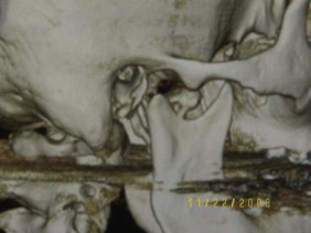
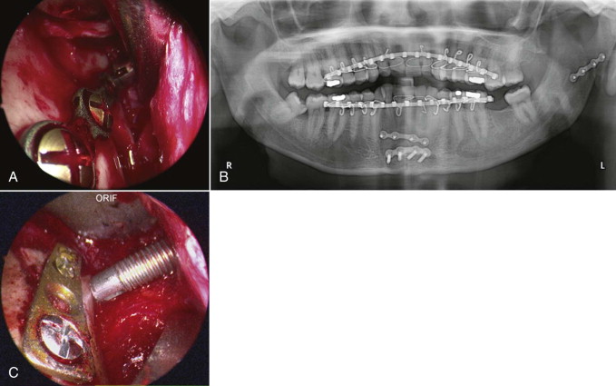
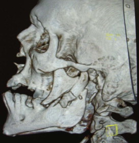
As far as the technique is concerned, in cases of subcondylar or condylar neck fractures where the condyle fragment is displaced but without dislocation, the fractures can be reduced and fixated via intraoral approach assisted with an endoscope. In condylar neck fractures with medial dislocation ( Fig. 6-11 ), endoscopic assisted reduction has proven to be very difficult by intraoral approach alone. A combined intraoral and extraoral approach would be indicated. Though two-plate fixation, adaptation plate fixation, and miniplate fixation have been used for ORIF, most authors agree that the single mini-dynamic compression plate is the most reliable, versatile, and consistent in performance, supported by a biomechanical assessment of performance.
Armamentarium
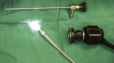
The basic surgical armamentarium includes a 4-mm-diameter straight endoscope with a 30-degree optic lens illuminated by a xenon light source (Karl Storz, Tuttlingen, Germany) ( Fig. 6-12 ), a video system, and a set for condylar fracture fixation system. The endoscope can be incorporated into a specifically designed tissue dissector or a modified posterior border retractor, part of the KLS or Synthes subcondylar fracture instrumentation that also includes the Snowden-Pencer suction tip elevator.
Endoscopically Assisted Orif for Nondislocated Condylar Fracture
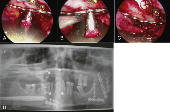
The intraoral mucosal incision is placed at the pterygomandibular raphe, on the anterior border of the ramus. The incision can be extended caudally to the vestibular mucosa corresponding to the mandibular first molar. Creation of an optical cavity follows. The subperiosteal dissection then exposes the lateral part of the mandibular ramus, posterior border, sigmoid notch, and gonial angle. The inferiorly inserting fibers of the temporalis are disconnected from the coronoid process. Next, a sigmoid notch retractor and a modified posterior border retractor are used to provide access for the endoscope and the plate fixation. The endoscope is inserted in the optical chamber, on the lateral aspect of the ramus, to verify the fracture line. Intermaxillary fixation in correct occlusion by means of arch bars is achieved next. The nondislocated or laterally dislocated condylar segment is reduced with instruments that each operator is comfortable with (Snowden-Pencer elevators, angled, straight, or various combinations). After the reduction of the proximal segment, the tip of the elevator is placed on the lateral surface of the fragment to temporarily stabilize its position. A titanium compression miniplate for condylar fixation will be adapted over the condylar segment and ramus ( Fig. 6-13, A and B ). The transoral endoscope provides good visibility of the fractured segment and the lower part of the plate. With endoscopic assistance, the condylar segment is fixated with one to three titanium screws via the transbuccal approach. The trocar will be inserted through a 3-mm stab incision in the tragal fold, inferior to the pinna. Precise anatomic reduction of the condylar segment over the mandibular ramus is achieved with a long periosteal elevator and modified condylar distracters. The fixation is then finalized with two to three titanium screws placed in a transbuccal ( Fig. 6-13, C ) or transoral location, using a right-angle screwdriver drill. The maxillary fixation is removed to check for occlusal shift. The surgical wound is closed primarily when a stable occlusion in retruded contact position is secured.
Endoscopically Assisted Orif for Dislocated Condylar Fracture
The condylar fracture medially dislocated is a contraindication for solely intraoral reduction. There are a variety of facial approaches to the condyle; however, the medially dislocated condylar fracture poses problems for all of them. The ramus fragment typically rises superiorly into the fossa and obscures the view of the dislocated fragment via the submandibular approach. Also, the length of the dissection from the tegument to the fracture site is significant enough to result in poor visibility even with additional light from the endoscope. On the other hand, the retromandibular approach confers good access to the condylar area because it is close to the fracture site. However, the necessary dissection of the marginal mandibular and buccal branches of the facial nerve from the parotid tissues increases the risk of damage to cranial nerve (CN) VII. The conventional preauricular approach leaves obvious facial scars. The next two techniques described are ones that have worked best at the hands of the authors.
The best access to the medially dislocated condyle is via the preauricular approach. Once the zygomatic arch and glenoid fossa are exposed by subperiosteal dissection, the displaced condyle can be mobilized back into the fossa with manipulation forceps. Reduction of the fracture is facilitated by forceful mouth opening to allow the fractured condylar head to be relocated in the fossa. The plate is adapted to the condylar segment and fixated with two to three screws. The endoscope is inserted intraorally and manipulated cranially to visualize the fractured condylar neck and inferior part of the plate. A rather precise anatomic reduction can be achieved by caudal traction on the plate attached to the condylar segment. Further stabilization is facilitated with periosteal elevators, angle elevators, modified posterior border retractors, or a combination of these. A 3-mm stab incision in the cutaneous fold inferior to the pinna will accommodate the transbuccal trocar. The final fixation is achieved with two transbuccal screws on the distal segment. The transbuccal trocar route can be avoided by using a right-angle screwdriver drill to apply the screws transorally. The intermaxillary fixation is then removed to evaluate occlusal stability.
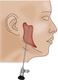
In the past few years, the Troulis submandibular approach has gained more favor in the eyes of these authors ( Fig. 6-14 ). It consists of a 1.5-cm subangulomandibular incision approximately 2 cm cervical to the angle. Dissection is carried sharply to the bone and then continued in a subperiosteal plane with suction-assisted endoscopic elevators, such as the Snowden-Pencer elevators, to create an optical space. The 30-degree Karl Storz endoscope can be placed parallel to the posterior border of the ramus, with direct access to the condyle. The anterior and posterior borders of the ramus, the sigmoid notch, the coronoid process, and the posterior body of the mandible are the relevant anatomic landmarks visualized once the scope is in the optic chamber. A curved, long-handled retractor is positioned to maintain the optical cavity. An osseous orifice is trepanned at the angle and a wire is passed to facilitate the distraction of the ramus. The authors prefer a mandibular angle clamp for the same purpose. With the patient in IMF, the distal and proximal fragments are identified through the endoscope. A long-handled, narrow-tipped clamp is used to apprehend the condylar neck and position the condylar head in the fossa. The fracture is reduced and the distracted ramus released, wedging the two segments together. A 2.0-mm (five hole) titanium plate is positioned, then the proximal screws are placed. The plate-holder/introducer is then removed and the plate used to manipulate the proximal segment. Reduction at the posterior border is evaluated and the distal screws are placed with or without the aid of a percutaneous trocar.
Advantages
The endoscopically assisted technique allows for direct visualization with operating field magnification. It awards such precise anatomic reduction that 85% to 95% of patients regain immediate postoperative function of the mandible with TMJ function restored to unrestricted pretrauma joint movement. All cases of early malocclusion are amenable to two to five days elastic IMF for stabilization of correct occlusion. The technique immediately restores chin point location and jaw line. It prevents lateral deviation with maximal IMO and TMJ luxation of the contralateral side, maintaining condylar head mechanics without remodeling. In the majority of cases, it eliminates the need for postoperative IMF. The small, remotely placed incisions leave minimal, inconspicuous scars. Minimal dissection and manipulation of tissues results in decreased pain, swelling, and overall morbidity; quicker recovery; and shorter hospital stay.
Endoscopically Assisted Open Reduction and Internal Fixation of Mandible Angle Fractures
The mandible angle fracture ( Fig. 6-15 ) is one of the most common injuries of the maxillofacial complex and may be treated in various ways. The endoscopically assisted technique is indicated, technically, in any angle fracture requiring internal fixation, including but not limited to a Champy plate, superior and inferior border plates, just inferior border plate, or miniplates.
The incision is similar to the one used for the standard intraoral approach for ORIF of the mandibular angle fracture. Next, the subperiosteal dissection will create an optical cavity. The 0-, 30-, or 45-degree, 4-mm diameter scope, xenon light source, and standard mandibular fracture instrumentation are used. Recommended specialized instruments are Minnesota, cheek, and trocar-cheek retractors with an endoscopic sleeve to improve visualization and decrease instrumentation in the cavity. The endoscope visualization of the fracture and inferior border of the mandible are ideal. Superior, tension, and inferior fixation plates are positioned and fixated using a single transbuccal trocar technique ( Fig. 6-16, A and B ). The optional locking cannula, the authors’ preference, also aids in the precise placement of fixation hardware. Once optimal fixation is achieved and reduction confirmed with the endoscope, appropriate documentation is recorded and closure completed ( Fig. 6-16, C and D ).
As with all other endoscopically assisted surgical techniques, the advantages by far outweigh the risks. There is no better way of verification for plate placement than the scope view. The angulation for screw placement is ideal (90 degrees). From the soft tissue perspective, there is less stretching and minimal dissection from the mandible. Immediate function of the mandible is less difficult. The reduction is precise enough that the surgeon can confidently remove the arch bars at the end of the procedure. Although initially the surgery will require approximately 2.5 times longer than the conventional technique, duration will decrease with experience. In these authors’ hands, the surgical time for an ORIF of an isolated angle fracture averages 45 minutes. As we see it, the only disadvantages of this technique are cost and manpower.
Other endoscopic applications in OMS include the endoscopically assisted ORIF of the isolated zygomatic arch fractures and the endoscopically assisted condylectomy and reconstruction.
Endoscopically Assisted Orthognathic Surgery
One of the major advances in oral and maxillofacial surgery in the 1990s was the introduction of the endoscope and lasers, which enables orthognathic surgery to be performed on outpatients. The endoscope facilitates osteotomies and fixation in a poorly accessed maxillofacial region by improving visibility and allowing precise anatomic alignment of the osseous fragments.
Intraoral Vertical Ramus Osteotomy/Vertical Subsigmoid Osteotomy
The intraoral vertical ramus osteotomy/vertical subsigmoid osteotomy (IVRO/VSO) is an osteotomy that is typically performed to correct mandible prognathism. Other indications for this procedure would include malocclusion secondary to malunion of a mandible fracture, condylar hyperplasia with asymmetric prognathism, and mandibular asymmetry secondary to Parry-Romberg syndrome. As in most orthognathic surgical procedures today, IVRO is usually performed transorally. This route has limited visibility and makes application of rigid fixation rather difficult. The role of the endoscope in IVRO/VSO is to facilitate surgical access to the sigmoid notch region during osteotomy and segment adaptation and fixation of proximal segments.
Surgical Technique
Stay updated, free dental videos. Join our Telegram channel
VIDEdental - Online dental courses


