Introduction
The strategic design of an appliance for correcting a bialveolar protrusion by using orthodontic mini-implant anchorage and sliding mechanics must take into account the position and height of the mini-implant, the height of the anterior retraction hook and compensating curve, and midline vertical traction. In this study, we used finite element analysis to examine effective en-masse retraction with orthodontic mini-implant anchorage and sought to identify a better combination of the above factors.
Methods
Base models were constructed from a dental study model. Models with labially and lingually inclined incisors were also constructed. The center of resistance for the 6 anterior teeth in the base model was 9 mm superiorly and 13.5 mm posteriorly from the midpoint of the labial splinting wire. The working archwires were assumed to be 0.019 × 0.025-in or 0.016 × 0.022-in stainless steel. The amount of tooth displacement after finite element analysis was magnified 400 times and compared with central and lateral incisor and canine axis graphs.
Results and Conclusions
The tooth displacement tendencies were similar in all 3 models. The height of the anterior retraction hook and the placement of the compensating curve had limited effects on the labial crown torque of the central incisors for en-masse retraction. The 0.016 × 0.022-in stainless steel archwire showed more tipping of teeth compared with the 0.019 × 0.025-in archwire. For high mini-implant traction and 8-mm anterior retraction hook condition, the retraction force vector was applied above the center of resistance for the 6 anterior teeth, but no bodily retraction of the 6 anterior teeth occurred. For high mini-implant traction, 2-mm anterior retraction hook, and 100-g midline vertical traction condition, the 6 anterior teeth were intruded and tipped slightly labially.
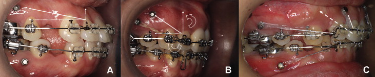
Orthodontic mini-implants (OMIs) are used for various anchorages. For treatment of bialveolar protrusion, anchorage preservation during space closure is important for maximum retraction of the anterior teeth after premolar extractions. OMIs have been reported to be effective anchorage for en-masse space closure ( Fig 1 ). In some patients, however, retroclined anterior teeth after maximum retraction can cause a poor esthetic outcome ( Fig 1 , B ).
The working rectangular wires for en-masse anterior retraction with an OMI and sliding mechanics can be made of 0.019 × 0.025-in (0.022-in slot) or 0.016 × 0.022-in (0.018-in slot) stainless steel (SS). The anterior retraction hook (ARH) is placed bilaterally between the lateral incisor and the canine at a height of 2 to 5 mm. The position of the OMI is about 10 mm above the posterior archwire.
Although we designed the retraction force vector through the center of resistance (CR) for the 6 maxillary anterior teeth, bodily tooth movement might not occur. Because these teeth were not splinted rigidly to form a multi-rooted tooth, a relatively flexible continuous full archwire was used. Furthermore, application of an experimental or estimated CR to a patient might be limiting.
The reaction of teeth to sliding mechanics can be analyzed by using finite element analysis (FEA). With 3-dimensional (3D) computer models, various conditions can be simulated by varying the simulation parameters. The initial reactions of the teeth, periodontal ligament (PDL), and alveolar bone can be evaluated qualitatively and quantitatively.
Major factors affect the accuracy of FEA including anatomic accuracy of the geometry of the finite element (FE) model and uncertainties about material properties and boundary conditions. In most previous studies, FE models were obtained by constructing coarse mapped meshes for manually modeled computer aided design (CAD) geometries, so that the resulting analyses cannot avoid inaccuracies. Recently, with the help of 3D laser scans and corresponding CAD-computer aided manufacturing technologies, anatomically correct 3D surface modeling has become popular. Innovatively increased performance of the central processor unit also enables fast FE modeling with fine tetrahedron solid elements with even better accuracy than time-consuming mapped meshes. In addition, the accuracy of FE models has been improved by the publication of newly calibrated material properties of the PDLs obtained from animal and cadaver studies.
In this study, we used FEA for an effective en-masse retraction design with orthodontic mini-implant anchorage. We examined the effect of anterior torque control as a function of the original anterior tooth axis, position, and height of the OMI, height of the ARH, compensating curve (CC), and midline vertical traction, and sought to identify a better combination of these factors.
Material and methods
The central incisor (tooth 11), lateral incisor (12), and canine (13) from a dental study model (i21D-400G, Nissin Dental Products, Kyoto, Japan) were scanned and aligned with a True-arch form (“A” Company, San Diego, Calif). The axes of these teeth were reproduced from the dental study model (base model). The thickness of the PDL was considered to be uniform (0.25 mm). The alveolar bone crest was constructed to follow the curve of the cementoenamel junction ( Fig 2 , A ) . Lingual and labial models were also constructed with the anterior teeth tipped lingually or labially by 10° compared with the base model ( Fig 2 , B and C ).
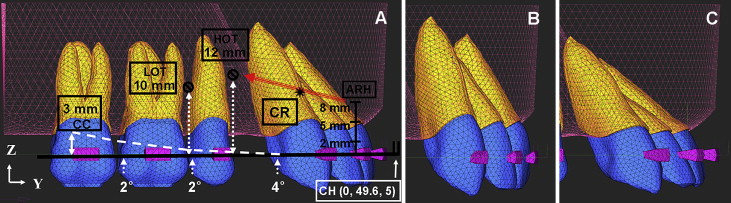
Using Ansys version 10 (Canonsburg, Pa), the archwire was modeled by beam 4 elements with a cross section of 0.019 × 0.025-in or 0.016 × 0.022-in SS wire. The ARH (0.05-in SS wire) was set between the lateral incisor bracket and the canine bracket bilaterally. The center hook was set at the midpoint of the archwire ( Fig 2 , A ).
At the connected nodes between the archwire and the brackets, translational degrees of freedom in the 2 flexural directions of the archwire were coupled to deform together, and translational degrees of freedom in the axial direction of the archwire were unconstrained.
Therefore, free axial rotation movement of the archwire in the brackets was allowed, while friction between the archwire and brackets along the axial direction was ignored.
In the system studied, the y-axis was the midsagittal line of the dental arch on the occlusal view, and the z-axis was perpendicular to the y-axis. The x, y, and z coordinates of the archwire midpoint were 0, 49.6, 5 in the base model ( Fig 2 , A ).
The total numbers of nodes (or total numbers of elements) comprising the model were 49039 (249796) for the base model, 48429 (246646) for the labial model, and 49039 (249796) for the lingual model. For the discretization of the teeth, the PDL, and the alveolar bone, 4-node tetrahedron element (ANSYS solid45) were used, and material properties in the models were assumed to be isotropic and homogeneous ( Table I ).
| Young’s modulus (g/mm 2 ) | Poisson’s ratio | |
|---|---|---|
| Teeth | 2E6 | 0.3 |
| Periodontal ligament | 5.0 | 0.3 |
| Alveolar bone | 2E5 | 0.3 |
| Stainless steel | 2E7 | 0.3 |
The position of the OMI was assumed to be 10 mm (low OMI traction) or 12 mm (high OMI traction) ( Fig 2 , A ). Retraction force vectors of 200 g from the ARH (0, 2, 5, and 8 mm) to low or high OMI traction were resolved into components along the x, y, and z axes and applied to the ARH ( Fig 2 , A ; Table II ).
| Traction type | Low OMI traction | High OMI traction | |||||
|---|---|---|---|---|---|---|---|
| ARH height | 0 mm | 2 mm | 5 mm | 0 mm | 2 mm | 5 mm | 8 mm |
| Fx (g) | 87.85 | 89.24 | 90.83 | 97.01 | 101.05 | 106.33 | 110.27 |
| Fy (g) | 169.85 | 172.50 | 175.60 | 142.91 | 148.86 | 156.64 | 162.44 |
| Fz (g) | 58.47 | 47.60 | 30.28 | 100.00 | 87.56 | 64.50 | 38.22 |
| Fz/Fy (%) | 34.40 | 27.60 | 17.20 | 70.00 | 58.80 | 41.20 | 23.50 |
For the 2-mm ARH and high OMI traction condition, the OMI between the central incisors was assumed to apply midline vertical traction. The additional intrusion force (50 or 100 g) from the center hook was combined to simulate the effect on labial crown torque ( Fig 2 , A ).
To simulate a 3-mm CC, 4°, 2°, and 2° V-bends were placed in the archwire between the distal side of the canine bracket and the mesial side of the second molar tube. The vertical distance from the second molar tube to the end of the curved archwire was 3 mm ( Fig 2 , A ).
The 6 anterior teeth of the base model were splinted with 0.3 × 0.3-in SS wire. The wire post was set at the midpoint of the labial splinting wire, and the wire frame was set at the lingual sides of the 6 anterior teeth. To find the CR of the 6 anterior teeth, a 200-g retraction or intrusion force was applied in a superior or posterior direction from the midpoint of the labial splinting wire at 0.5-mm intervals ( Fig 3 , A ) . After simulation, the initial tooth displacement was magnified 400 times. The CR was estimated from the point of force application that resulted in bodily movement of the 6 anterior teeth in the base model. The CR was 9 mm superiorly and 13.5 mm posteriorly from the midpoint of the labial splinting wire ( Fig 3 , B ).
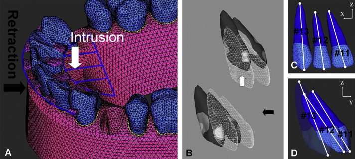
For the analysis, ANSYS software was used on the personal-computer platform with a Pentium 4 central processor unit (3.0 GHz, Intel, Santa Clara, Calif). The deformed shapes of the teeth were studied with the tooth axis graph in the y-z plane. The axes of teeth 11, 12, and 13 were constructed by connecting the y and z coordinates of the nodes at the root apex and crown (middle of the incisor edge or canine tip; Fig 3 , C and D ). The y and z coordinates of each node after displacement of the teeth were calculated by adding the initial displacement of the node that was magnified 20 times to the y and z coordinates of each node before displacement.
When a force is applied to a tooth, initial movement is produced, and then orthodontic movement starts. Therefore, it is important to clarify the forces applied to the teeth and the stresses produced in the PDL at initial movement. If the magnitudes of these forces and stresses are not suitable to produce bone remodeling, orthodontic movement might not start.
In this study, hydrostatic stresses were calculated to investigate the tensile or compressive status of the PDL: σH = (σ1 + σ2 + σ3)/3, where σ1, σ2, and σ3 denote the principal stresses.
Results
Low OMI traction with 0.019 × 0.025-in SS wire in the labial, base, and lingual models was measured. For the system with 0-mm CC and 0-mm ARH, teeth 11, 12, and 13 were tipped lingually by en-masse retraction in all 3 models. As the height of the ARH increased (2 or 5 mm), lingual tipping of teeth 11 and 12 reduced more than with the 0-mm ARH ( Fig 4 , Table III ). The incisor axes, however, did not reach the original axes in the 3 models. For the 3-mm CC, tooth 13 reached its original axis, but there was no effect on tooth 11 in any model.
| Tooth | Axis | Original coordinates | Low OMI traction | ||||||
|---|---|---|---|---|---|---|---|---|---|
| 0-mm ARH | 5-mm ARH | 5-mm ARH + 3-mm CC | |||||||
| Crown | Apex | Crown | Apex | Crown | Apex | Crown | Apex | ||
| 11 | y | 45.8279574 | 33.5601520 | −1.309E-01 | 3.096E-02 | −8.872E-02 | 7.485E-04 | −7.672E-02 | −6.129E-03 |
| z | 0.5000000 | 21.5338045 | −4.497E-02 | 4.803E-02 | −8.569E-03 | 4.453E-02 | −3.039E-04 | 4.272E-02 | |
| 12 | y | 43.2892962 | 29.5725181 | −1.280E-01 | 6.809E-03 | −8.598E-02 | −2.873E-02 | −6.331E-02 | −3.879E-02 |
| z | 0.2564025 | 20.0000000 | −2.977E-02 | 6.440E-02 | 7.463E-03 | 5.023E-02 | 2.680E-02 | 4.172E-02 | |
| 13 | y | 38.5166876 | 28.6921322 | −5.911E-02 | 1.279E-02 | −5.760E-02 | 2.184E-02 | −1.405E-02 | −8.599E-03 |
| z | −0.9141889 | 24.5369266 | −1.295E-02 | 2.367E-02 | −4.322E-02 | 1.257E-03 | −1.623E-02 | −3.915E-03 | |
With low OMI traction with 0.016 × 0.022-in SS wire, the lingual tipping tendencies in the labial, base, and lingual models were similar to that observed for the 0.019 × 0.025-in SS archwire. For the 2-mm ARH and 0-mm CC condition, the tooth axes after displacement in the 3 models were compared ( Fig 5 , Table IV ). Because 0.016 × 0.022-in SS wire is more flexible than 0.019 × 0.025-in wire, there was more labial tipping of tooth 12 and more distal tipping of tooth 13. A 3-mm CC in the 0.016 × 0.022-in SS wire did not reduce distal tipping of tooth 13 more than with the 0.019 × .025-in SS wire ( Fig 6 , Tables III and IV ).


