Introduction
The aim of this study was to evaluate the impact of the placement angle on the stability of loaded microscrews.
Methods
Forty-eight microscrews were placed at 4 angles ( 30°, 50°, 70°, and 90°) into the tibiae of 12 beagles, loaded with a force of 2 N immediately, and maintained for 8 weeks. Microcomputed tomography and pullout tests were used for morphometric and biomechanical analyses, respectively.
Results
All microcomputed tomography parameters and the peak loads at extraction of the microscrews were influenced by the placement angles of the microscrews. The higher microcomputed tomography parameters and the peak load at extraction were measured at angles from 50° to 70°. Oblique and vertical placement angles resulted in reduced stability of the loaded microscrews ( P <0.05).
Conclusions
To achieve the best stability of microscrews, a placement angle of 50° to 70° is advisable.
The biocompatibility of titanium screws in bone tissue was noticed in the 1960s, and the concept of osseointegration was introduced because light microscopic examinations showed bone-to-implant contact. From then on, many studies were focused on investigating the application of titanium implants in dentistry. An implant success rate of over 90% has been reported in edentulous patients. Decades ago, the idea of using dental implants to reinforce orthodontic anchorage showed encouraging results.
For a successful orthodontic treatment, anchorage had to be controlled well. Many anchorage methods, including intraoral and extraoral appliances, were devised. However, most intraoral appliances showed some loss of anchorage. Without patient compliance, extraoral appliances do not provide reliable anchorage. Compared with traditional anchorage, the major advantages of microscrews are small size, minimal anatomic limitations for placement, lower medical costs, simpler placement and removal surgeries, less discomfort after placement, and the possibility of immediate or early loading. Moreover, microscrews can provide effective anchorage that does not depend on patient compliance. With more patients treated with microscrews as anchorage, their stability is gathering attention.
The generally accepted protocol for the successful and predictable placement of stable microscrews includes use of a biocompatible material, an atraumatic surgical technique, and an appropriate load. Moreover, the stresses at the interface between the microscrews and the bone are determined by the healing time before loading, and the period, magnitude, and direction of the load. Research results of applied forces and healing times before loading have been reported in many studies, but few have focused on the direction of the applied forces. Orthodontic forces are parallel to the surface of the cortical bone; therefore, the placement angle of microscrews influences the direction of orthodontic forces. Moreover, microscrews are normally placed between the roots of the teeth, or in the palatal or retromolar area. Thus, the risk of injury to dental roots should not be underestimated. To avoid root damage, Park et al introduced oblique microscrew placement as a substitute for the traditional perpendicular placement because more space was available near the apical region, and a recent study proved that slightly oblique placement angles resulted in increased primary stability. However, some clinicians have pointed out that obliquely placed microscrews obtains reduced stability and inferior anchorage quality, because oblique placement may result in shallower depth of microscrews. So, the actual impact of different placement angles on the stability and anchorage quality of the microscrews remains unknown.
This study was designed to investigate the impact of the placement angle on the stability of loaded microscrews by analyses with microcomputed tomography (μCT) and pullout tests.
Material and methods
Twelve male beagles (age, 24 months; weight, about 12.5 kg) were supplied by the Experimental Animal Center of Sichuan University in Chengdu, China. All beagles were handled according to an experimental protocol approved by the Bioethics Committee of Sichuan University.
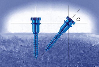
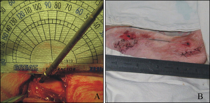
The beagles were randomized according to a computer-generated randomization list in sealed, opaque envelopes into 4 groups to receive microscrews at different angles (α = 30°, 50°, 70°, and 90°) ( Fig 1 ), and every group had 3 dogs. All surgical procedures were performed under systemic (1 mg/kg ketamine and 2 mg/kg intramuscular xylazine) (North China Pharmaceutical Group Corp., Shijiazhuang, China) and local (2% lidocaine with 1:80 000 epinephrine) anesthesia. Forty-eight microscrews (height, 6 mm; diameter, 1.6 mm; Medicon, Tuttlingen, Germany) were prepared for placement. The mesial and distal metaphyses of the tibiae were chosen as the experimental sites and exposed through skin incisions. The surface of the tibiae was surgically exposed by blunt dissection. All microscrews was placed with a drilling method. The microscrew was placed with a handheld screwdriver so that there was no space between bone and collar ( Fig 2 , A ). For each tibia, 2 microscrews were placed (1 microscrew’s placement angle was α, and the other angle was 180°-α). They were immediately loaded with a force of 2 N with a closed-coil spring between the implanted pairs ( Fig 2 , B ). Each animal received 4 microscrews. All beagles were kept for 8 weeks before they were killed.
The animals were killed with a lethal dose of pentobarbital. The tibiae with the microscrews were separated from the animals and carefully sectioned into small blocks, each containing 1 microscrew, which was surrounded by at least 5 mm of bone without soft tissue ( Fig 3 , A ). All bone-microscrew blocks were subsequently transferred into 10% buffered formalin at 4°C for fixation.
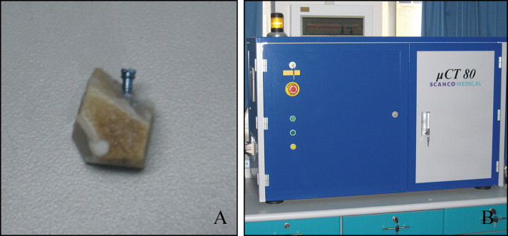
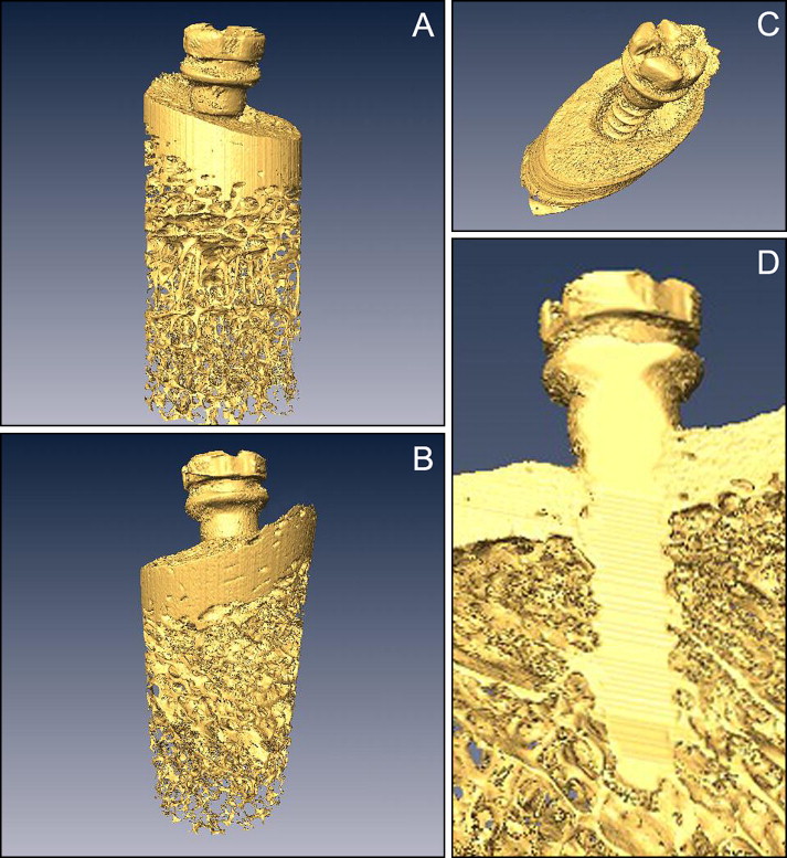
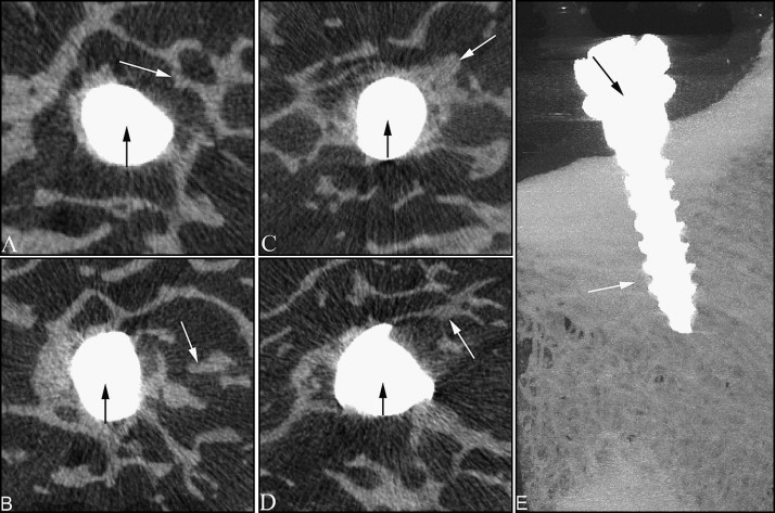
After 2 weeks of fixation, the specimens were prepared for μCT investigation; the proximal 5 mm of the bone was examined by a μCT imaging system (μCT 80, Scanco Medical, Bassersdorf, Switzerland) ( Fig 3 , B ). The scan conditions were 70 kV with 300 ms integration time and 114 mA. Microtomographic slices were acquired at 1000 projections at a spatial nominal resolution of 20 μm. For a detailed qualitative and quantitative 3-dimensional evaluation, those images were reconstructed and analyzed (CT Analyser, Skyscan, Kontich, Belgium) ( Fig 4 , A and B ). The titanium and mineralized tissue were segmented from each other and from the bone marrow, including the immediate microscrews’ vicinity, by applying a multi-level thresholding procedure. The peri-implant trabecular bone (PIB) volume of interest included the entire trabecular compartment within 1.0 mm around the microscrew ( Fig 4 , D ). The following morphometric parameters were calculated in the PIB: bone volume density (bone volume/total volume) (BV/TV), trabecular thickness (Tb.Th), trabecular number density (Tb.N), and intersection surface (the area of the bone surface contacting the microscrews) (IS). Osseointegration (OI) was calculated as the ratio of IS to the surface areas of the intraosseous microscrews.
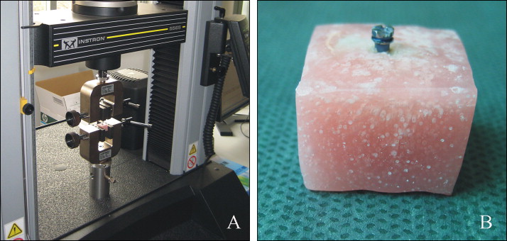
After the μCT analysis, pullout testing was performed by using a materials test system (5565, Instron, Canton, Mass) ( Fig 5 , A ). The bone specimen was embedded in polymethylmethacrylate (Dental Products, Heraeus, Hanau, Germany), vertical to the longitudinal axis of the microscrew, with the microscrew head exposed so that the testing machine could tightly clamp the block and pull the microscrew head by a jig ( Fig 5 , B ). For pullout testing, the microscrews were aligned with the axis of the testing machine to ensure that no bending moment was created during the test, and only axial pullout strengths were recorded. The microscrews were pulled out at a crosshead speed of 0.05 mm per second. The applied load was monitored, and the peak load at extraction (F MAX ) was obtained from the data file.
Statistical analysis
SigmaStat software (SPSS, Chicago, Ill) was used throughout. Differences in morphometric and biomechanical parameters were analyzed by analysis of variance (ANOVA). When significant differences were indicated by ANOVA, group means were compared by using the Student-Newman-Keuls method for multiple comparisons. P values less than 0.05 were considered to be the level of statistical significance. Spearman or Pearson correlation coefficients were calculated to assess the relationship between placement angle, OI, and F MAX of the pullout test. This coefficient test was used at the level of P <0.05.
Results
The microscrews’ survival rates were 100% for all groups, and all microscrews remained stable throughout the study. Using settings of the μCT system that resulted in enhanced x-ray transmission through the titanium microscrews, we generated high-resolution tomographic images that clearly depicted the bone-microscrew interface; thus, we could identify the bone in contact with the microscrew and quantify the OI. These images demonstrated that the angle of placement influenced the measured μCT parameters about both OI and PIB density ( Fig 6 ). Quantitatively, when the 50°, 70°, and 90° groups were compared with the 30° group, there was a statistically significant increase in the OI ( P <0.05). Both the 50° and 70° groups showed statistically significant increases in the OI over the 90° group ( P <0.05). The comparison between the 50° and 70° groups showed no significant differences ( P >0.05) ( Table 1 ). As for the PIB, we compared each group with each other, and all showed significant differences except for the comparison of the 50° group with the 70° group in BV/TV ( Table 1 ). In Tb.Th, as the placement angle was changed, the 50°, 70°, and 90° groups showed 238%, 262%, and 197% higher Tb.Th values, respectively, compared with the 30° group ( P <0.05) ( Table 1 ). The Tb.N showed the same pattern compared with the OI, with higher values in the 50° and 70° groups ( P <0.05) ( Table 1 ). The morphometric parameter that had the most correlation with OI was the IS, which assessed the contact areas between the bone and the microscrews. Its value in the 30° group was 3.95 mm 2 , and the 50° group had a higher value (8.41 mm 2 ) than the 30° group ( P <0.05). With the increment of placement angle, IS values of the 70° group (8.72 mm 2 ) were significantly enhanced ( P <0.05). However, those of the 90° group (6.39 mm 2 ) were significant reduced ( P <0.05) ( Table 1 ). Moreover, in the 30° group, we saw resorption of cortical bone around the microscrews in the reconstructed μCT images ( Fig 4 , C ).
To assess the biomechanical influence of the placement angle, we used the pullout test. The F MAX reflects the degree of integration of titanium microscrews and bones, and pullout tests probe the biomechanical properties of the bones surrounding the microscrews. The results showed that the F MAX of the pullout test was influenced by the angle of placement. The 50°, 70°, and 90° groups were compared with the 30° group; this indicated a statistically significant increase in the F MAX ( P <0.05). The comparison between the 50° and 70° groups showed no significant difference ( P >0.05), and the 70° group showed a statistically significant increase in the F MAX over the 90° group ( P <0.05) ( Table I ).


