Introduction
The aim of this study was to evaluate the stress state in the cortical bone around an orthodontic microimplant during and after the insertion surgery.
Methods
The self-tapping insertion of an orthodontic microimplant into 1-mm-thick cortical bone containing a predrilled hole was simulated by using a 3-dimensional finite element method. The entire insertion surgery was replicated by a total of 3601 calculation steps: ie, the first 3600 dynamic steps analyzing the insertion process and an additional static step for analyzing the residual stress state after insertion. Four microimplants were experimentally inserted into rabbit tibiae to measure the insertion torques and compare them with the finite element analysis results.
Results
Reasonable agreement was observed between the experimentally measured and the finite element calculated torques, confirming the validity of our finite element simulation, which showed that high stresses can develop in the interfacial bone during microimplant insertion. Hoop stresses above the ultimate tensile strength and radial stresses above the ultimate compressive strength of cortical bone developed in the bone. Furthermore, residual radial stresses higher than the critical threshold stress to trigger pathologic bone resorption were observed after insertion. These high insertion-related stresses implied that it is not the orthodontic force or the timing of its application, but the insertion conditions that can determine the bone’s response to the microimplant and its clinical prognosis.
Conclusions
This in-vitro finite element analysis showed that, during the self-tapping insertion of orthodontic microimplants, stresses high enough to fracture cortical bone can develop. After the self-tapping insertion, the radial stresses calculated at the interfacial bone were higher than the threshold value to trigger pathologic bone resorption.
Overload is identified as a major risk factor for the failure of orthodontic microimplant treatment. Since stresses or strains higher than a certain threshold can trigger pathologic changes in the bone, an overloaded implant, either an orthodontic microimplant or a dental implant, is prone to lose its osseous support and loosen, and it might fail if the situation is left unaddressed.
A number of studies, experimental and numeric, have already been carried out to investigate the effects of microimplant size: length and diameter, shape and design, insertion angle and characteristics of the implant bed bone, and the presence or distance of adjacent teeth on the bone stresses. Unfortunately, however, most of these studies have focused exclusively on the effect of orthodontic forces. Stresses from another important source—those caused by the placement of the microimplant—have generally been ignored.
Stresses created at the point of insertion might need more attention because, although strong primary stability is a prerequisite for the clinical success of a microimplant, a tight fit between the microimplant and the bone can create high stresses at the interface. The immediate or early loading protocol used routinely in microimplant therapy will not allow sufficient time for bone to relieve these insertion stresses by remodeling or other relaxation mechanisms. Therefore, it is quite likely that the interfacial bone is subjected to a certain level of residual stress before orthodontic forces are applied.
Recent experimental studies have shown that the insertion stresses by themselves—ie, before the application of force to the microimplant—are high enough to cause cracks in bone. This suggests that biomechanical analysis should take into account the insertion stresses as well as those from the orthodontic forces. Accordingly, this study was designed to evaluate the stresses developing in the cortical bone during microimplant placement. The primary goal was to test whether a finite element simulation can reliably replicate the dynamic self-tapping insertion procedure.
Material and methods
The geometries of microimplants (AbsoAnchor SH1312-07; Dentos, Daegu, Korea) and a cortical bone plate, shown in Figure 1 , were created by using a computer-aided design program (Autodesk Inventor, San Rafael, Calif). The microimplant has a slightly tapered body (diameters, 1.3 mm at the cervix and 1.2 mm at the apex). Its shaft, 6.5 mm in length, has a V-shaped, 0.25-mm-high machined thread on the surface. By referring to a previous study, we designed a coin-shaped bone specimen, 1 mm thick and 2.6 mm in diameter, containing a through-thickness predrilled hole of 0.9 mm in diameter. To minimize the finite element model size, cancellous bone was not included in the analysis.
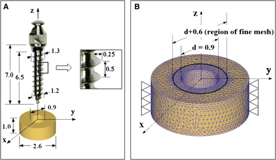
With the DEFORM 3-dimensional program (version 6.1; Scientific Forming Technologies, Columbus, Ohio), the finite element simulation was designed to resemble clinical practice as closely as possible. As shown in Figure 1 , the microimplant was initially placed above the bone with its center line collinear with that of the hole. It was then moved down along the line until its apical threads came into contact with the hole wall. The finite element simulation of the self-tapping insertion was then started under displacement-controlled conditions. The microimplant was programmed to rotate and advance into the hole continuously, at a rotation speed of 30 rpm and an advancement speed of 0.25 mm per second; therefore, every 2 seconds, the microimplant rotated 1 turn and advanced 0.5 mm downward: ie, the pitch of the microimplant’s thread. A total of 3600 calculation steps were used to simulate the 10 turns and 5 mm of advancement of the microimplant into the hole. After this, the displacement condition imposed on the microimplant was removed (which replicated the detachment of the insertion driver from the microimplant’s head), and the final residual stress state was calculated.
The 3-dimensional mesh of the bone specimen consisted of approximately 45,000 4-node tetrahedron elements. A finer mesh was used around the hole, where the interaction between the microimplant and bone mainly occurs. The element size within 0.25 mm from the hole wall was one fifth of those without, as shown in Figure 1 , B . The initial mesh, however, was subjected to continuous changes, since an automatic remeshing scheme was used to accommodate the deformation of the interfacial bone in accordance with the microimplant insertion. All nodes on the outer perimeter of the bone were clamped as geometric boundary conditions. The kinetic friction coefficient between the microimplant and the bone during the insertion was assumed to be constant at 0.1.
Large deformation of the interfacial bone was expected during microimplant insertion, inducing stresses above the yield strength of the cortical bone. Therefore, not only elastic but also plastic material behavior should be considered. Due to the lack of literature reporting the elasto-plastic properties of the human jaw cortical bone, leg bone data were taken from the literature. The use of leg cortical bone data can be justified because of the close similarity in the elastic modulus between the leg bones (16.8 GPa; Fig 2 ) and jaw bones used in several implant studies; it was in the range of 13.7 to 20 GPa. Figure 2 shows the graphic stress-strain relationship that was reconstructed and used in this study. The ultimate strength (138.76 MPa) shown in Figure 2 was the tensile strength. The compressive strength was set to 198.22 MPa, 30% higher than the tensile strength based on previous studies.
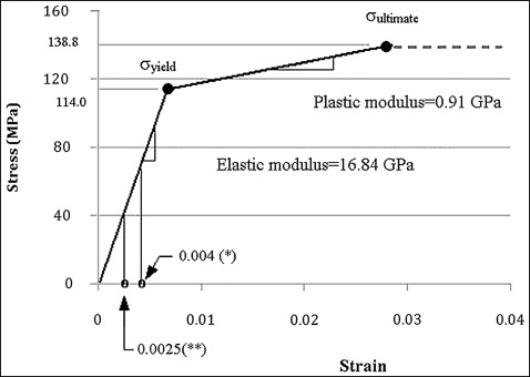
To predict the postoperative response of the interfacial bone, the critical threshold stress was defined as –67.37 MPa. This corresponds to –4000 microstrains that has been described as the threshold strain to trigger pathologic bone resorption.
The titanium alloy (Ti-6Al-4V) microimplant was modeled as a rigid material to allow for faster calculations on the assumption that deformations in the microimplant would be insignificant compared with those in the interfacial bones.
To verify the validity of our finite element simulation, an animal experiment was conducted. The tibial middiaphysis of a mature white rabbit, 12 months old, weighing approximately 3.0 kg, was used to provide cortical bone of a similar quality to that used in the finite element analysis. The experimental protocol was approved by the Animal Care Committee of the School of Dentistry at Kyungpook National University in Korea.
Two microimplants were inserted into each of both tibiae with the self-tapping method (left, sites 1 and 2; right, sites 3 and 4). Pilot holes were drilled at a right angle to the bone surface with a 0.9-mm drill bit at 500 rpm under external saline irrigation to minimize the risk of thermal damage. The microimplants were then driven into the holes at 30 rpm with a surgical engine (Elcomed SA-200C; W&H Dentalwerk Buermoos GmbH, Buermoos, Austria). With a built-in torque meter, the insertion torque was recorded throughout the insertion process with a sampling time of 0.125 second and an accuracy of .001 Ncm. Four more orthodontic microimplants (2 in each tibia) were inserted with the self-drilling method for another study, which is not described here. All surgeries were performed by an experienced orthodontist.
After insertion, the microimplants were driven out, and the tibiae were cut into pieces so that each piece had 1 implantation site. The bone thickness was then measured with a caliper.
Results
The bone thicknesses measured at the 4 implant sites were 1.10 mm (sites 1 and 2), 0.95 mm (site 3), and 1.15 mm (site 4). At site 4, a macroscopic crack running across the hole was found, so the torque data recorded there were discarded. Figure 3 shows the torque values measured at the other 3 sites together with one calculated by the finite element simulation. Reasonable agreement between the measured and calculated values was observed.
Figures 4 and 5 show the radial and hoop stresses developing in the interfacial bone during microimplant insertion. For an easy examination, stresses in the cross-section (cut by the y-z plane) of the bone specimen are shown. The radial stress ( Fig 4 ) is the stress component that developed as a direct result of the microimplant’s thread pressing the pilot-hole wall. On the other hand, the hoop stress ( Fig 5 ) is the stress component acting in a tangential direction around the hole as a result of the diameter differences between the microimplant and the hole. In Figures 4 and 5 , either compressive or tensile ultimate strength of the cortical bone was selected as the cutoff value: red , where stresses exceed the ultimate compressive strength; and blue , where stresses exceed the ultimate tensile strength. All parts of Figures 4 and 5 represent a typical stage of microimplant placement. Overall, the radial stresses are compressive or neutral ( Fig 4 ), whereas the hoop stresses are tensile ( Fig 5 ).


