Introduction
The aim of this study was to compare the virtual and manual tooth setups with digital and plaster models in extraction cases by measuring various occlusal parameters and applying the American Board of Orthodontics objective grading system.
Methods
Linear intra-arch and interarch dimensions (arch width and length, perimeter, overjet, and overbite), angular variables (tip, torque, and rotation), and American Board of Orthodontics objective grading system scores obtained from a digital virtual setup model were compared with those from a plaster model setup.
Results
The digital virtual setup model resulted in smaller arch perimeters than did the plaster setup model by 2.20 mm in the maxillary arch ( P <0.01) and 1.30 mm in the mandibular arch ( P <0.05). The digital virtual setup also exhibited significantly lower values for overbite and overjet ( P <0.01). The digital virtual setup had tendencies toward mesial angulation of the anterior teeth, labial inclination of the maxillary anterior teeth ( P <0.05), and distal in-rotation of the mandibular teeth ( P <0.05). The resulting American Board of Orthodontics objective grading system evaluation showed that larger deductions for overjet, occlusal contact, and total score ( P <0.01) were required for the digital than for the manual setup model.
Conclusions
Digital and manual setups lead to similar measurements for intra-arch and interarch occlusal variables. However, because of the possibility of collision on proximal and occlusal contact, delicate adjustments in proximal and occlusal contacts are required.
The use of 3-dimensional (3D) digital models in orthodontics is increasing because of the development of 3D image-taking techniques. The advantages of 3D digital models include no extra space required for storage, ease of data searching and classification, the possibility of accurate analysis, and a simplified method of transferring data. The use of 3D digital models is broadening with the development of 3D digital scanners and software that transforms scanned data into images.
The 3D digital model in orthodontics has found applications in analysis of various models for diagnosis and treatment planning, setups for the visualization of treatment objectives, quality assessment of treatment results, 3D analysis of tooth movements after orthodontic treatment, and the production of customized orthodontic appliances with CAD/CAM or the rapid prototyping technique.
In recent years, 3D digital models have also been used to generate setups and to allow indirect bracket positioning of customized orthodontic appliances. For example, SureSmile (Orametrix, Richardson, Tex) takes real-time in-vivo images that recompose into a 3D digital model and process the diagnostic setup. In addition, OrthoCAD (Cadent, Carlstadt, NJ) converts plaster models into a stereolithography file, producing 3D digital models, and the virtual setup is carried out with such models. The Incognito appliance (3M Unitek, Monrovia, Calif) produces 3D digital models by converting conventional setup models with the guidance of an orthodontist’s prescription and ultimately produces customized brackets with CAD/CAM. The Orapix 3D dental system (Seoul, Korea) is another method of bracket bonding that uses a rapid-prototype jig facilitating indirect bonding. This system runs 3D software allowing analysis and diagnosis using a 3D digital model produced by scanning a plaster model with the 3D optical laser scanner; it also carries out the 3D virtual setup according to the treatment plan. In addition, it ultimately finalizes bracket positioning and produces a transfer jig in the virtual setup model. Likewise, by fabricating a transfer jig with a virtual setup, indirect bonding has been widely used to simplify laboratory procedures in lingual orthodontics. An understanding of virtual setups with 3D digital models is required to gain a satisfactory treatment result.
A number of recent case reports have involved the 3D virtual setup systems. These reports have included technical proposals regarding the virtual setup technique and studies concerning the accuracy of 3D digital models; however, no study has explored the standards and characteristics of a virtual setup using 3D digital models. Therefore, the aim of this study was to compare virtual and manual tooth setups with digital and plaster models in extraction cases.
Material and methods
The study subjects consisted of 10 orthodontic patients whose maxillary and mandibular first premolars were extracted to improve mild crowding and profile protrusion. No congenitally missing teeth or tooth size discrepancies were present in any patients.
To produce the 3D digital models, a 3D optical laser scanner (Orapix KOD-500), with a resolution of approximately ±15 μm, was used to scan the maxillary and mandibular models and the occlusal views. The scanned data were saved as a stereolithography file and converted into a 3D digital model using the 3Txer program (Orapix). An orthodontic specialist (J.I.) confirmed the scanning conditions and the occlusion of the 3D digital model.
The study was performed in 2 ways: a manual setup of a plaster model with the initial plaster model of the study subjects, and a virtual setup of a 3D digital model. The setup was based on the anchorage requirements, the final desired position for the whole maxilla and mandible according to the treatment plan, the expected torque loss related to wire play and other factors, the amount of overcorrection for rotation control, and the arch forms. These cornerstones were established under the instruction of an experienced orthodontic specialist (J.-Y.C.).
The dental sections of the subjects’ initial plaster models were separated on the articulator, and the setup was conducted according to the orthodontist’s prescription. The manual setup model of the plaster model was digitized using a 3D optical laser scanner (Orapix KOD-500) for 3D digital analysis.
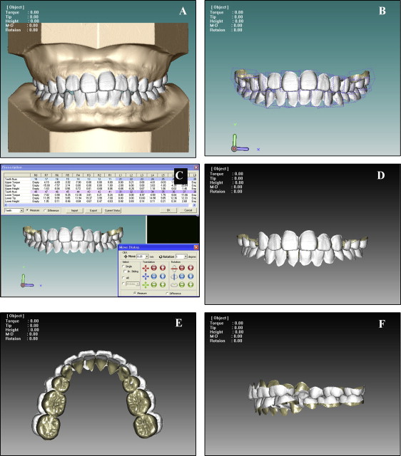
The 3D digital model and the virtual setup procedures are outlined in Figure 1 . The virtual setup was conducted using the 3Txer program (Orapix). Each dental unit consisted of an individual section of teeth from the 3D digital model. The axes were set, and the individual teeth were digitized by normalizing each dental unit. Thereafter, the appropriate arch form was selected individually, and the remaining dentition, apart from the first premolars planned for extraction, was primarily arranged through automatic alignment based on the incisal surfaces of the normalization or the occlusal plane. Manual adjustment of individual teeth to their ideal positions was performed according to the treatment plan. Finally, the occlusion of the maxilla and mandible was assessed and resolved. Each setup method was performed by an experienced setup technician with an identical treatment plan and completed by the orthodontist (J.-Y.C.) after the final check and corrections.
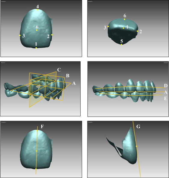
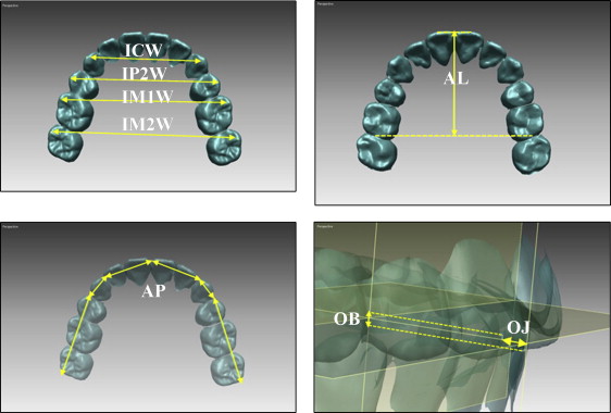
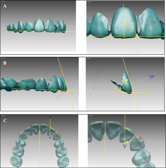
Definitions of the reference planes and landmarks are provided in Figure 2 . Linear and angular variables were measured using Rapidform 2006 (Inus Technology, Seoul, Korea). Reference lines and landmarks for the linear and angular measurements and the definitions of angulation, inclination, and rotation are described in Figures 3 and 4 .
Quality assessments of each setup method were conducted using the American Board of Orthodontics (ABO) calibration kit. To assess the virtual setup model, the rapid prototyping model (ProJet HD 3000; TPM, Greenville, SC) was produced with a 3D printer with a resolution of ±20 μm. The plaster model was assessed directly.
Seven of the 8 categories of the ABO objective grading system (OGS) were used in this assessment (alignment, marginal ridge, buccolingual inclination, occlusal relationship, occlusal contact, overjet, and interproximal contact). Root parallelism, which can be assessed with a panoramic radiograph, was excluded.
Statistical analysis
SPSS software (version 17.0; IBM, Chicago, Ill) was used for the statistical analysis of the reference points and measurements. To assess the reliability and reproducibility of the study, all variables were measured twice with a 1-month interval. The intraclass correlation coefficient was used to assess reliability. The Wilcoxon signed rank test was used to compare the difference in each variable (arch dimensions, angular variables, and ABO OGS) between the manual and virtual setups.
Results
The intraclass correlation values ranged from 0.880 to 0.998 ( P <0.001); all measured variables therefore had high reliability. The manual setup exhibited greater values for all arch dimensions except for UIM1W ( Table I ). The variable with the greatest difference in value was UAP (2.20 mm, P <0.01). The manual group also exhibited greater overbite and overjet values (0.50 and 0.46 mm, respectively), and there were statistically significant differences in UAL (0.55 mm, P <0.05), LIP2W (0.96 mm, P <0.05), LIM1W (1.46 mm, P <0.05), and LIM2W (1.25 mm, P <0.05) ( Table I ).
| Manual setup mean (mm) | Virtual setup mean (mm) | Mean difference (mm) | P value | ||
|---|---|---|---|---|---|
| Maxillary | ICW | 37.65 (36.87, 38.42) | 37.07 (36.18, 37.98) | 0.57 (−0.01, 1.15) | 0.114 |
| IP2W | 45.62 (44.89, 46.34) | 45.02 (44.13, 45.90) | 0.60 (0.02, 1.19) | 0.059 | |
| IM1W | 51.01 (50.18, 51.83) | 51.14 (50.40, 51.88) | −0.13 (−0.59, 0.33) | 0.508 | |
| IM2W | 57.62 (56.41, 58.83) | 56.96 (55.67, 58.26) | 0.66 (−0.10, 1.41) | 0.114 | |
| Arch length | 31.73 (30.89, 32.57) | 31.19 (30.29, 32.08) | 0.55 (0.01, 1.08) | 0.047 ∗ | |
| Arch perimeter | 105.74 (103.43, 108.06) | 103.55 (101.29, 105.80) | 2.20 (1.26, 3.13) | 0.007 ∗ | |
| Mandibular | ICW | 28.35 (27.84, 28.86) | 28.13 (27.31, 28.96) | 0.22 (0.53, 2.40) | 0.575 |
| IP2W | 36.44 (35.82, 37.05) | 35.48 (34.32, 36.64) | 0.96 (0.24, 2.26) | 0.037 ∗ | |
| IM1W | 42.17 (41.27, 43.07) | 40.71 (39.26, 42.15) | 1.46 (0.01, 1.08) | 0.013 ∗ | |
| IM2W | 49.37 (48.10, 50.63) | 48.12 (46.47, 49.77) | 1.25 (−0.61, 0.75) | 0.028 ∗ | |
| Arch length | 27.77 (27.03, 28.51) | 27.70 (26.81, 28.59) | 0.07 (−0.61, 0.75) | 0.721 | |
| Arch perimeter | 99.09 (97.15, 101.04) | 97.75 (95.37, 100.13) | 1.34 (0.18, 2.51) | 0.028 ∗ | |
| Overjet | 3.15 (2.90, 3.39) | 2.68 (2.45, 2.92) | 0.46 (0.22, 0.74) | 0.005 † | |
| Overbite | 1.95 (1.70, 2.19) | 1.45 (1.22, 1.68) | 0.50 (0.25, 0.74) | 0.005 † |
The assessment of the symmetry of each model showed statistically significant differences in U2 (1.94°, P <0.05) and L3 (1.96°, P <0.01) regarding tip of the manual setup, and in U1 (0.57°, P <0.05), U5 (2.42°, P <0.05), U7 (2.29°, P <0.05), and L5 (1.57°, P <0.01) regarding rotation; torque did not differ significantly ( Table II ). When the left and right sides of the virtual setup were compared, statistically significant differences were observed for U1 (1.02°, P <0.05) and U2 (1.68°, P <0.01) regarding tip, and for U5 (1.98°, P <0.05) in terms of rotation; there was no difference in torque between the left and right sides ( Table II ).
| Manual setup | Virtual setup | |||||
|---|---|---|---|---|---|---|
| Tip (°) | Torque (°) | Rotation (°) | Tip (°) | Torque (°) | Rotation (°) | |
| U1 | 0.16 (−0.65, 0.97) | −0.63 (−1.40, 0.14) | 0.57 (0.13, 1.01) | 1.02 (0.11, 1.91) | −0.32 (−1.15, 0.52) | 0.15 (−0.20, 0.50) |
| U2 | 1.94 (0.34, 3.54) | −0.42 (−2.34, 1.50) | 0.38 (−0.49, 1.25) | 1.68 (0.72, 2.64) | 0.63 (−0.69, 1.94) | 0.62 (−0.16, 1.40) |
| U3 | −0.03 (−1.61, 1.56) | −0.19 (−1.11, 0.73) | 0.49 (−0.81, 1.78) | 0.21 (−1.21, 1.63) | 0.24 (−1.43, 1.91) | 0.28 (−1.30, 1.85) |
| U5 | −0.23 (−2.58, 2.12) | 0.50 (−0.88, 1.87) | 2.42 (0.92, 3.94) | 0.58 (−1.50, 2.66) | 0.68 (−1.69, 3.05) | 1.98 (0.73, 3.24) |
| U6 | −0.29 (−1.47, 0.90) | 1.17 (−0.66, 2.99) | −0.32 (−2.12, 1.49) | 0.63 (−1.01, 2.26) | 0.04 (−2.26, 2.35) | 0.22 (−1.18, 1.62) |
| U7 | 0.45 (−1.75, 2.65) | 0.76 (−1.25, 2.76) | −2.29 (−4.07, −0.51) | −1.12 (−2.68, 0.45) | 0.62 (−1.80, 3.04) | −1.33 (−2.83, 0.17) |
| L1 | 0.56 (−0.33, 1.44) | −0.15 (−1.08, 0.78) | 0.33 (−0.25, 0.90) | 0.57 (−0.04, 1.18) | −0.30 (−0.93, 0.34) | 0.59 (−0.01, 1.20) |
| L2 | 0.02 (−0.84, 0.89) | −1.02 (−2.55, 0.51) | −0.06 (−0.80, 0.69) | −0.62 (−1.64, 0.40) | −0.63 (−1.81, 0.55) | 0.35 (−1.25, 1.96) |
| L3 | 1.96 (0.75, 3.18) | −0.20 (−1.80, 1.40) | −0.31 (−1.93, 1.31) | 0.31 (−1.18, 1.80) | 0.31 (−0.66, 1.28) | 0.95 (−0.84, 2.74) |
| L5 | 0.05 (−2.12, 2.23) | 0.86 (−1.37, 3.09) | 1.57 (0.83, 2.13) | −0.71 (−2.59, 1.17) | 0.87 (−1.14, 2.89) | 0.29 (−0.89, 1.46) |
| L6 | −0.40 (−1.73, 0.94) | 0.13 (−0.97, 1.24) | 0.20 (−1.08, 1.48) | −0.28 (−2.33, 1.77) | −1.09 (−2.34, 0.17) | 0.04 (−1.20, 1.28) |
| L7 | −0.54 (−1.71, 0.63) | −1.68 (−4.65, 1.29) | 0.58 (−1.46, 2.61) | 0.90 (−0.92, 2.73) | 0.80 (−0.38, 1.98) | 0.50 (−1.29, 2.28) |
Comparison of the angular variables between the manual and virtual setups showed statistically significant differences in U1 (−1.21°, P <0.01), U5 (−1.16°, P <0.05), and L2 (−1.19°, P <0.01) with respect to tip ( Table III ). The following values also had statistically significant differences: U1 (2.78°, P <0.05), U2 (3.42°, P <0.01), U3 (2.00°, P <0.05), and L3 (1.75°, P <0.05) for torque; and U6 (2.98°, P <0.01), L2 (2.30°, P <0.01), L6 (1.45°, P <0.01), and L7 (1.73°, P <0.05) for rotation ( Table III ). The virtual setup had greater tip difference values in all categories except U6. The manual setup exhibited greater torque difference values for the entire maxillary dentition and greater rotational differences throughout the mandibular dentition ( Table III ).
| Tip (°) | Torque (°) | Rotation (°) | ||||
|---|---|---|---|---|---|---|
| Difference | P value | Difference | P value | Difference | P value | |
| U1 | −1.21 (−1.87, −0.54) | 0.003 † | 2.78 (0.76, 4.79) | 0.030 ∗ | −0.79 (−1.93, 0.34) | 0.179 |
| U2 | −1.07 (−2.31, 0.17) | 0.218 | 3.42 (1.04, 5.80) | 0.005 † | 0.81 (−0.39, 2.02) | 0.232 |
| U3 | −1.05 (−2.39, 0.30) | 0.135 | 2.00 (0.17, 3.85) | 0.025 ∗ | −0.15 (−2.04, 1.74) | 1.000 |
| U5 | −1.16 (−2.20, −0.11) | 0.033 ∗ | −0.43 (−1.91, 1.05) | 0.526 | 0.62 (−1.18, 2.42) | 0.737 |
| U6 | 1.21 (−0.20, 2.62) | 0.093 | −0.14 (−1.84, 1.56) | 0.896 | 2.98 (1.03, 4.94) | 0.009 † |
| U7 | −2.30 (−4.95, 0.36) | 0.126 | 0.23 (−1.66, 2.12) | 0.263 | 0.49 (−2.34, 3.32) | 0.627 |
| L1 | −0.64 (−1.28, 0.00) | 0.059 | 0.00 (−1.89, 1.90) | 0.940 | 0.27 (−0.46, 1.00) | 0.765 |
| L2 | −1.19 (−1.96, −0.42) | 0.009 † | 0.77 (−1.20, 2.74) | 0.351 | 2.30 (1.07, 3.53) | 0.002 † |
| L3 | −0.33 (−1.65, 0.99) | 0.911 | 1.75 (0.21, 3.30) | 0.030 ∗ | 1.73 (−0.03, 3.50) | 0.048 |
| L5 | −0.56 (−2.52, 1.40) | 0.502 | 0.50 (−0.92, 1.93) | 0.654 | 1.20 (−0.51, 2.71) | 0.062 |
| L6 | −0.74 (−1.20, 1.06) | 0.881 | −0.17 (−1.85, 1.51) | 0.911 | 1.45 (0.44, 2.46) | 0.012 ∗ |
| L7 | −0.65 (−2.22, 0.91) | 0.502 | −0.92 (−2.59, 0.75) | 0.100 | 1.73 (−0.06, 3.53) | 0.040 ∗ |
Stay updated, free dental videos. Join our Telegram channel
VIDEdental - Online dental courses


