Introduction
The purpose of this study was to examine the effect of orthopedic forces on maxillary first molars’ and maxillary central incisors’ pulp chambers in children having rapid maxillary expansion as the only intervention compared with children having no orthodontic intervention by using cone-beam computed tomography images.
Methods
In this prospective controlled clinical study, we evaluated 60 maxillary first molars and 60 maxillary central incisors from 30 children (18 boys, 12 girls) in the mixed dentition and during the pubertal growth period. The treated group had rapid maxillary expansion with the Haas expander, followed by 6 months of retention and 6 months of follow-up out of retention; the control group had no intervention during the study. Cone-beam computed tomography scans were taken initially and 1 year after the rapid maxillary expansion active phase. Initially, a 3-dimensional scrolling in all pulp chambers of the evaluated teeth was performed with Dolphin Imaging software (version 11.0; Dolphin Imaging & Management Solutions, Chatsworth, Calif) to describe the incidence of pulp-chamber calcifications. The dimensions of the pulp chambers of the molars and incisors were also investigated. Cross-sectional and longitudinal slices were used for each molar (coronal and axial slices) and incisor (sagittal and axial slices). The area (mm 2 ) was obtained from 3 slices of each kind (6 measurements for each tooth).
Results
The results suggest that rapid maxillary expansion did not induce new pulp-chamber calcification. Also, it did not interfere in normal pulp-chamber dimension changes of the anchorage molars.
Conclusions
The pulp chamber of the central incisors can be expected to be minimally wider 1 year after the therapy.
No orthopedic procedure has been so investigated in orthodontics since the mid 1960s as rapid maxillary expansion (RME); nevertheless, some questions still remain unanswered. Its immediate and long-term effects have been recently confirmed in a meta-analysis and several systematic reviews. However, none of these studies evaluated the changes in pulp dimensions.
Structural and functional normality of the pulp tissues seems to be influenced by local and systemic factors. Circulatory disturbances with congested and dilated blood vessels, odontoblastic degeneration, vacuolization, and edema of the pulp tissues can be cited as iatrogenic pulp reactions to orthodontic forces. The basis of RME is to produce orthopedic forces (range, 7.54-15.8 kg) that maximize skeletal separation of the midpalatal suture before dental movement or physiologic sutural adjustment can occur. Once expansion forces are applied, the anchorage teeth are given a heavy force until the suture ruptures. At this moment, the central incisors are abruptly moved apart as a diastema develops, and the roots of the maxillary central incisors diverge laterally. Besides the extreme force generated during the active phase, the maxillary displacement during the retention period could also cause changes on the pulp anatomy that are unexpected during normal development.
Some authors have stated that teeth receiving orthodontic forces occasionally have pulp and root canal atresia, and they have also suggested that these injuries might be permanent and that the pulp could eventually lose its vitality. However, according to other studies, these changes have no significant long-lasting effects on the dental pulp, and they are called regressive or degenerative. In addition, it is said that orthodontic forces do not cause pulp changes such as increased numbers of pulp nodules, calcic metamorphosis of the pulp, permanent vascular changes, and early pulp aging represented by hyalinization of the extracellular matrix and fibrosis.
Few studies evaluating RME effects on the pulp cavity have been conducted. Babacan et al found that pulp blood flow values of anchorage teeth were doubled in the first week of expansion and decreased after the midpalatal suture separation. The pulp blood flow values tended to reach their initial values during the retention period and were similar to the initial values in the final evaluation (after 12 weeks of retention). Cho et al reported reversible changes after RME using an electric pulp tester and cold test.
Although these clinical changes seem to be reversible, the pulp modifications that had occurred in attempts to reverse the treatment effects could have affected the natural development of the pulp cavity in treated children. No clinical study has investigated the following questions. What changes can be expected on the pulp dimensions of anchorage molars and central incisors 1 year after RME? Are these changes similar to the those observed in normal development? Therefore, the purpose of this study was to examine the long-term effects of orthopedic forces on the pulp chambers of maxillary first molars and central incisors in children having RME as the only intervention compared with children with no orthodontic intervention by using cone-beam computed tomography (CBCT) images.
Material and methods
This study was approved by the Institute of Collective Health Studies Research Ethics Committee of the Universidade Federal do Rio de Janeiro in Brazil (0044.0.239.000-11). Informed consent was signed by all parents or guardians of the patients before the clinical procedures. In this prospective controlled clinical study, we evaluated 30 children (18 boys, 12 girls; mean ages, 9 years 7 months and 9 years 4 months, respectively), previously admitted to the Department of Orthodontics and Pediatric Dentistry of the Universidade Federal do Rio de Janeiro before intervention and after a 1-year interval.
The inclusion criteria were early mixed dentition, Class I or Class II skeletal pattern, growth period (skeletal maturation CS1 through CS3 as evaluated by the cervical vertebral maturation method ), no major systemic disease, no use of any medication, healthy dentition (no carious lesions or extensive restorations), no history of dental trauma, and no endodontically treated teeth. Subjects were added to the treated group when they needed RME therapy.
The decision to use RME therapy was clinically based on a posterior transverse interarch discrepancy, measured as the difference between the maxillary and mandibular intermolar widths. Maxillary skeletal transverse deficiency (distance from J point to facial frontal line >12 mm ) was confirmed for all subjects in the treated group.
The RME group consisted of 15 children (8 boys, 7 girls; mean age, 9.6 years; range, 7 years 8 months-11 years 6 months) consecutively having RME therapy with a soft-tissue–borne Haas-type appliance, standardized with stainless steel wire with a diameter of 0.047 in (Rocky Mountain Orthodontics, Denver, Colo) and an expansion screw of 11 mm (Magnum 600.303.30; Dentaurum, Ispringen, Germany), connected to banded first permanent molars and first deciduous molars. When it was not possible to band the first deciduous molars, the appliance was bonded to them. All patients were treated by the same operator (C.B.), and the Haas activation protocol for children less than 14 years old was used. The expander was activated 1 complete turn (0.8 mm) at placement. After the initial activation, each patient’s parent was instructed to activate the expansion screw daily, a quarter turn in the morning and a quarter turn in the evening, until the expansion required was achieved (according to the skeletal deficiency). The progress was observed every week during the active phase (2-3 weeks). Then, the screw was fixed with a 0.012-in double-thread ligature and kept in place passively for 6 months of retention, when the expander was removed. The patients were followed for the next 6 months.
The control group included 15 children (10 boys, 5 girls) from 7 years 6 months to 11 years 4 months of age (mean age, 9.4 years). They met all the inclusion criteria and had no need for orthodontic intervention during the next year.
All patients were given oral hygiene instructions and were closely monitored to prevent inflammation of the gingival tissues during the study. After the 6 months of the retention period, a follow-up program was instituted until the eruption of all permanent teeth (except third molars). In the proper period, all patients who need orthodontic intervention will be treated in the orthodontic postgraduate clinics of the Department of Orthodontics and Pediatric Dentistry of the Universidade Federal do Rio de Janeiro.
CBCT scans were taken initially and 1 year after the RME active phase. A similar interval between the scans was designed for both groups. All scans were taken in the same cone-beam machine (i-CAT; Imaging Sciences International, Hatfield, Pa), according to a standard protocol (120 kV, 5 mA, FOV 16 × 22 cm, voxel 0.4 mm, and 20 s of scan time). During scanning, all patients were in maximum intercuspation.
The data from the 2 scans were exported in DICOM (digital imaging and communication in medicine) format and imported into the Dolphin 3D software (version 11.0; Dolphin Imaging & Management Solutions, Chatsworth, Calif) for further analysis.
Once imported, each 3-dimensional volumetric data set was standardized by using reference planes with specific software tools. This procedure was necessary to replicate the 3-dimensional volumetric data set positions at the 2 times. The simultaneous view of volume and multiplanar reconstructions (sagittal, axial, and coronal) allowed 3-dimensional scrolling and dimension measurements in the pulp chambers of the maxillary first molars (n = 60) and the maxillary central incisors (n = 60).
All CBCT scans were handled and analyzed by the same examiner (M.A.Jr.) in a darkened room. The scans were randomly selected, and the examiner was blinded to both the group and the time being evaluated. Also, to distinguish the pulp cavity from the dentin, all images were standardized for brightness and contrast, and magnified by the same amount. Each tooth analyzed was previously oriented according to the following 3-step process.
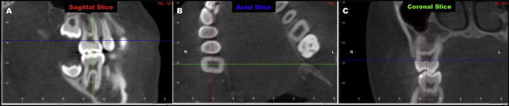
For the maxillary first molar, on the axial slice, the sagittal plane was adjusted to produce a better view of the pulp chamber. On this sagittal slice, the molar was rotated until its mesial and distal aspects of the cementoenamel junction intersected the axial plane. The coronal plane was also moved to pass through the center of the buccal groove ( Fig 1 , A ). On the axial slice, the sagittal and coronal planes were displaced to intersect the center of the tooth. After establishing this axis of rotation (intersection point), the tooth was rotated until the sagittal plane passed parallel to the alignment of the tooth ( Fig 1 , B ). On the coronal slice, the axial plane was moved until it intersected 1 aspect (buccal or palatal) of the cementoenamel junction; then the tooth was rotated until the axial plane intersected both the buccal and palatal aspects of the cementoenamel junction ( Fig 1 , C ).
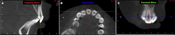
For the maxillary central incisor, on the 3-dimensional reconstruction view, the sagittal plane was moved to intersect the center of the central incisor. Then, on the sagittal slice, the central incisor was rotated until the buccal and lingual aspects of the cementoenamel junction intersected the axial plane. The coronal plane was also displaced on the sagittal slice to produce the best view of the pulp chamber on the coronal view ( Fig 2 , A ). On the axial slice, the sagittal and coronal planes were moved to intersect the middle of the crown. After establishing this intersection point, the tooth was rotated so that the sagittal plane passed through its most buccal and palatal aspects ( Fig 2 , B ). On the coronal slice, the sagittal plane was moved to intersect the middle of the pulp chamber, and the incisor was then rotated until the sagittal plane intersected the apex and the middle point in the incisal border ( Fig 2 , C ).
Subsequently, sagittal, axial, and coronal ( Figs 1 and 2 ) scrolling was performed in all pulp chambers of the teeth evaluated (n = 120). The aim of this 3-dimensional scrolling was to describe the incidence of pulp-chamber calcifications. Definite radiopaque focuses inside the radiolucent pulp chambers of the molars and incisors were defined as pulp-chamber calcifications. When the pulp chamber was completely radiolucent, that tooth was scored as a tooth without pulp-chamber calcifications. No attempt was made to determine the details of the pulp stones, such as their numbers, size, and location in the pulp chamber.
The dimensions of the pulp chambers of the molars and incisors were also investigated. Cross-sectional and longitudinal slices were used for each molar (coronal and axial slices) and incisor (sagittal and axial slices). The area (mm 2 ) was obtained from 3 slices of each kind (6 measurements for each tooth).
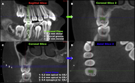
The measurements for the maxillary first molar were, on the coronal slices passing the buccal groove, 0.2 mm mesial to the buccal groove and 0.2 mm distal to the buccal groove in the sagittal view, and on the axial slices, passing 0.2, 0.4, and 0.6 mm apical from the cementoenamel junction in the coronal view ( Fig 3 ). In the coronal slices, a line parallel to the axial plane passing through the lowest point in the pulp-chamber upper wall was the upper limit for area measurement.
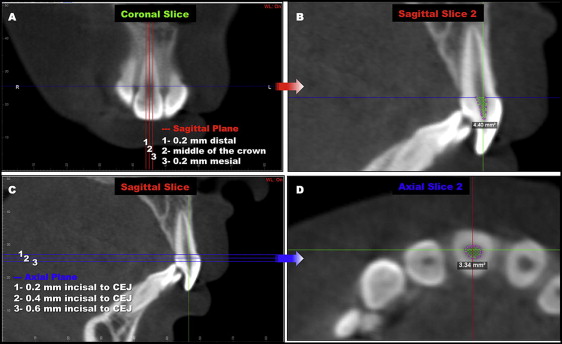
The measurements for the maxillary central incisor were, on the sagittal slices passing on the middle of the crown, 0.2 mm mesial to the middle of the crown and 0.2 mm distal to the middle of the crown in the coronal view, and on the axial slices, 0.2, 0.4, and 0.6 mm incisal from the buccal and palatal aspects of the cementoenamel junction in the sagittal view ( Fig 4 ). In the sagittal slices, a line passing through the cementoenamel junction determined the upper limit for area measurement.
The Statistical Package for the Social Sciences (version 17.0; SPSS, Chicago, Ill) was used to analyze the results, and P <0.05 was considered statistically significant. The intraclass correlation coefficient test (ICC) was applied to assess intraexaminer concordance (95% CI) for all variables. Sixteen CBCT images were randomly selected, and all measurements were repeated within 1 week. Descriptive statistical analyses (means and standard deviations) were carried out for all variables in the 2 scans. After the assessment of the normal distribution of the data (Kolmogorov-Smirnov test), the paired Student t test was used to identify statistically significant differences between the 2 scans in each group. Changes over time between the treated and control groups were compared with the independent sample Student t test.
Results
Table I details in both groups, the number and sex of the subjects, initial age, mean CBCT interval, number of evaluated teeth, and the numbers and percentages of total of pulp calcifications found in the 2 scans.
| n ∗ (boys/girls) | Initial age (y) | Mean interval T2-T1 (y) | Maxillary first molars evaluated (n) | Maxillary central incisors evaluated (n) | Pulp stones T1 n † (%) ‡ | Pulp stones T2 n † (%) ‡ | |
|---|---|---|---|---|---|---|---|
| RME group | 8/7 | 9.6 | 1.25 | 30 | 30 | 2 (3.3) | 2 (3.3) |
| Control group | 10/5 | 9.4 | 1.33 | 30 | 30 | 1 (1.7) | 1 (1.7) |
Stay updated, free dental videos. Join our Telegram channel
VIDEdental - Online dental courses


