Introduction
In the absence of adequate animal or in-vitro models, the biomechanics of human malocclusion must be studied indirectly. Finite element analysis (FEA) is emerging as a clinical technology to assist in diagnosis, treatment planning, and retrospective analysis. The hypothesis tested is that instantaneous FEA can retrospectively simulate long-term mandibular arch retraction and occlusal plane rotation for the correction of a skeletal Class III malocclusion.
Methods
Seventeen published case reports were selected of patients treated with statically determinate mechanics using posterior mandible or infrazygomatic crest bone screw anchorage to retract the mandibular arch. Two-dimensional measurements were made for incisor and molar movements, mandibular arch rotation, and retraction relative to the maxillary arch. A patient with cone-beam computed tomography imaging was selected for a retrospective FEA.
Results
The mean age for the sample was 23.3 ± 3.3 years; there were 7 men and 10 women. Mean incisor movements were 3.35 ± 1.55 mm of retraction and 2.18 ± 2.51 mm of extrusion. Corresponding molar movements were retractions of 4.85 ± 1.78 mm and intrusions of 0.85 ± 2.22 mm. Retraction of the mandibular arch relative to the maxillary arch was 4.88 ± 1.41 mm. Mean posterior rotation of the mandibular arch was –5.76° ± 4.77° (counterclockwise). The mean treatment time (n = 16) was 36.2 ± 15.3 months. Bone screws in the posterior mandibular region were more efficient for intruding molars and decreasing the vertical dimension of the occlusion to close an open bite. The full-cusp, skeletal Class III patient selected for FEA was treated to an American Board of Orthodontics Cast-Radiograph Evaluation score of 24 points in about 36 months by en-masse retraction and posterior rotation of the mandibular arch: the bilateral load on the mandibular segment was about 200 cN. The mandibular arch was retracted by about 5 mm, posterior rotation was about 16.5°, and molar intrusion was about 3 mm. There was a 4° decrease in the mandibular plane angle to close the skeletal open bite. Retrospective sequential iterations (FEA animation) simulated the clinical response, as documented with longitudinal cephalometrics. The level of periodontal ligament stress was relatively uniform (<5 kPa) for all teeth in the mandibular arch segment.
Conclusions
En-masse retraction of the mandibular arch is efficient for conservatively treating a skeletal Class III malocclusion. Posterior mandibular anchorage causes intrusion of the molars to close the vertical dimension of the occlusion and the mandibular plane angle. Instantaneous FEA as modeled here could be used to reasonably predict the clinical results of an applied load.
Highlights
- •
En-masse retraction of the mandibular arch efficiently treats skeletal Class III malocclusions.
- •
Posterior mandible anchorage results in molar intrusion.
- •
Finite element analysis can predict the clinical results of an applied load.
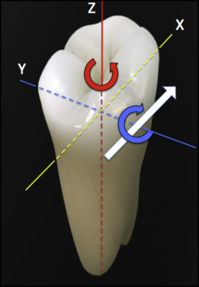
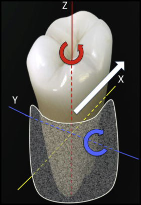
In orthodontics, the term “biomechanics” is often restricted to the physics of mechanics. Forces and moments can be calculated in 3 dimensions for statically determinate mechanics: those that can be calculated using the principles of static equilibrium (Newton’s laws) ( Fig 1 ). However, biomechanics is actually the science of how applied loads affect biologic structures, such as the supporting periodontium ( Fig 2 ). Rather than relating to the center of mass, as for a tooth in space ( Fig 1 ), the response to an applied force is relative to the center of resistance of the supported root ( Fig 2 ). Forces and moments can be measured or calculated for individual teeth along an archwire, but the boundary conditions, such as bracket engagement, effects of adjacent teeth, and the variance of the load delivered over time, are difficult to control. Typical archwires deliver unknown loads to the supporting tissues in an undefined manner: the biologic black box. Unfortunately, there are no appropriate bench or animal models for comprehensive clinical orthodontics. Realistic studies must be performed on the clinical records of specific patients.
This article assesses a novel clinical method for conservative treatment of a skeletal malocclusion and evaluates the biomechanical predictability of the clinical response at the level of the periodontal ligament (PDL), with advanced engineering technology. Since this information is intended for clinicians, a succinct review of some fundamental principles of mechanical engineering, relative to the unique material properties of the PDL and other supporting tissues, is required to convey the clinical significance of the finite element analysis (FEA) reported. The following terms are defined.
- 1.
Tension , compression , shear , and torsion are illustrated in Figure 3 .
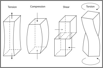
Fig 3 In mechanics, there are 4 fundamental loads, which elicit a distinct response in a loaded material: tension, compression, shear, and torsion. According to Poisson’s ratio, loading in tension and compression results in narrowing or widening of the loaded structure as its length changes. See text for details. - 2.
Tensors are a continuous mathematical framework in physics. Scalars are the base of the scale: zero-order tensors with magnitudes but no directionality. Vectors , first-order tensors, possess magnitude and direction ( Fig 4 , A ). In addition, a force vector has a point of application and a line of action. Within a loaded structure, external loads (forces and moments) are expressed as stresses (second-order tensors) ( Fig 4 , B ). Stress is a higher-order term than a vector (force) because it is more complex (force/unit area). The mechanical properties of the more complex (higher-order) tensors provide the mathematical relationships between stresses and strains. Young’s modulus of elasticity (material stiffness) and Poisson’s ratio (ratio of deformation, in the perpendicular dimension, as a material is stretched or compressed in the axial direction) are specific constants for each material ( Fig 3 ). In the most general state, the number of independent stresses is reduced to 6 ( Fig 4 , C ). Fortunately, with respect to controlling the complexity of calculations, there is an orientation where the shear stresses equal zero, and then the associated normal stresses are referred to as principal stresses (σ n ). σ 1 is maximal, σ 2 is intermediate, and σ 3 is minimal principal stress. All principal stresses may exist in compression or tension, but σ 1 is the most tensile (or least compressive), and σ 3 is the most compressive (or least tensile). σ 3 is particularly important in orthodontics because it is directly related to PDL necrosis and the path of tooth movement. Common but less mathematically precise designations for σ 1 , σ 2 , and σ 3 are P1, P2, and P3, respectively ( Fig 4 , D ).
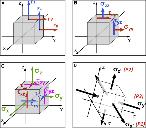
Fig 4 A, An imaginary, infinitesimally small cube, cut out from within any loaded structure (beam, truss, bone, PDL, root), experiences internal forces. Two such force components are shown acting on 2 of the 6 cube faces. On the top surface, Fz is the “normal” (perpendicular) force. Fy is a “shear” force because it acts within that plane. On the right surface, Fy becomes the normal force, and Fz becomes a shear force. Similar relationships apply to the other 4 faces of the cube. The Fz and Fy normal forces are shown in tension ( arrow pointing away from the surface ), but they can also be in compression ( arrow pointing into the surface ). B, When a force component is divided by the area of the surface on which it acts, it becomes a stress component (second-order tensor). The first subscript indicates the plane, and the second subscript indicates the direction of the component. Thus, the normal stresses are typically denoted as σ xx , σ yy , and σ zz , but they can be expressed as σ x , σ y , and σ z without the redundancy of the double subscripts. Compressive normal stresses are negative, whereas tensile stresses are positive. The shear stresses are generally written as τ xy , τ xz , τ yz , τ yx , τ zx , and τ zy . Again, the drawing shows only 2 planes, but the same relationship applies to the other 4 faces of the cube. C, The most general state of stress is illustrated for 3 faces of the cube. Equilibrium dictates that some (opposing) stresses are equal, so τ xy = τ yx , τ xz = τ zx , and τ yz = τ zy , thus reducing the number of independent components to 6. D, It is possible to calculate an orientation of the imaginary cube where all shear stresses equal 0. That orientation is the principal direction (x′-y′-z′), and the associated normal stresses are then principal stresses, σ x′ , σ y′ , and σ z′ . All principal stresses can be in compression or tension, but the relative order is fixed. The most tensile (least compressive) of the 3 (σ x′ , as drawn) is the maximum principal stress, which is designated as P1 . The most compressive (least tensile) (σ y′ ) is P3 , the minimum principal stress. The second (intermediate) principal stress, P2 , is in between (σ z′ ). - 3.
Force is an interaction that tends to change the motion of an object; in the current context, forces deform structures. It is a vector with direction, magnitude, line of action, and frequency (if intermittent). Its unit of measurement is the newton (N), about 102 g at Earth’s gravity.
- 4.
Stress is the internal force per unit of area, and its unit of measurement is the pascal (Pa): 1 N per square meter. As previously explained, stress is a second-order tensor with 6 independent components, representing the normal and shear stresses in each plane ( Fig 4 , B ). A pascal is a very small value, so most relevant physiologic stresses are expressed in kilo (k), mega (M), or giga (G) pascals, which are 10 3 , 10 6 , or 10 9 , respectively.
- 5.
Pressure is a scalar quantity, so the stresses (compressive or tensile) are the same in all directions (isotropic).
- 6.
Strain is deformation per unit of length. The term is dimensionless because it is a relative reference, similar to a percentage. For example, a 100-mm length of bone flexed (bent) or elongated by 1 mm is exposed to a 1% deformation or a 0.01 strain. Bone will typically fracture when bent by about 2.5%, so a full “unit” of strain (ε) is a large distortion that considerably exceeds the ultimate strength of the bone. It follows that the physiologic influence of strain on a living bone is at the microstrain (με) level, which is 10 −6 strain or 10,000 με. Frost’s mechanostat ( Fig 5 ) summarizes the differential bone response to varying levels of strain.
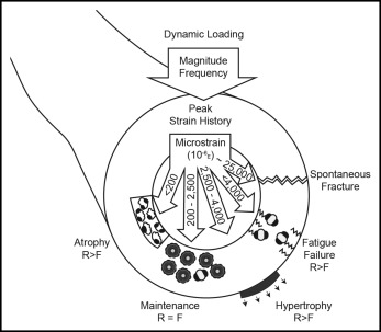
Fig 5 Frost’s mechanostat describes the relationship of bone strain to the progressive hierarchy of bone atrophy, maintenance, hypertrophy, fatigue failure, and spontaneous fracture. The relative effects on bone resorption ( R ) and formation ( F ) are illustrated. See text for details. - 7.
FEA is a numeric method ( Fig 6 ) for calculating the levels of stress in a homogeneous or composite structure, based on the material properties of each of its components.
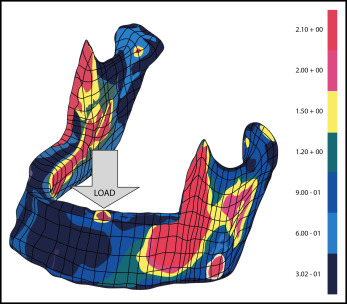
Fig 6 A color illustration of an early finite element model of the human mandible, originally published in black and white, shows the stress distribution in megapascals, relative to a 1-N load applied to the left first premolar area ( arrow ). The mandible is a cantilever exposed to substantial bending and torsion, particularly in the posterior body, mandibular ramus, and coronoid process, as designated by the yellow , orange , and red areas. See the study of Paydar et al for details.
Statically determinate mechanics
The term “biomechanics” is usually applied to the static equilibrium of applied loads, but statically determinate mechanics are typically restricted to simple collinear forces or 2 parallel force-1 couple, 2-dimensional (2D) systems. For 3D statically determinate systems, there can be 3 force components and 3 moment components. In the absence of true 3D mechanics, orthodontists typically apply 2D mechanics in the sagittal and frontal planes, but that approach falls short of a true 3D statically determinate system. Movement of multiple teeth with a flexible archwire is indeterminate ( Fig 7 , A and B ), but en-masse movement of an entire dental arch as a segment may be determinate ( Fig 8 ) if there is negligible change in the relative positions of individual teeth as the segment is moved. A rigid wire completely filling the slot on every tooth is not required, but the archwire must provide sufficient torque control to prevent changes in the axial inclination of the teeth in the segment.
Stay updated, free dental videos. Join our Telegram channel
VIDEdental - Online dental courses


