Introduction
Currently, cone-beam computed tomography (CBCT) has been widely used because of its capacity to evaluate the anatomic structures of the maxilla, mandible, and teeth in 3 dimensions. However, articles about the use of CBCT to evaluate the relationships between the morphology of individual teeth and torque expression remain rare. In this study, we aimed to determine the influence of labial crown morphologies and collum angles on torque for maxillary anterior teeth using CBCT.
Methods
A total of 206 extracted maxillary anterior teeth were selected to establish scanning models using dental wax, and they were scanned by CBCT. Three-dimensionally reconstructed images and median sagittal sections of the teeth were digitized and analyzed with AutoCAD software (Autodesk, San Rafael, Calif). The angle α, formed by the intersection of the tangent at a certain vertical height on the labial surface from the incisal edge with the crown long axis, and the collum angle, were measured.
Results
The variations in angle α at different heights from the incisal edge for the same type of tooth were statistically significantly different ( P <0.001). Moreover, the variations between collum angles and 0° for any type of maxillary anterior tooth were statistically significant ( P <0.01).
Conclusions
This study suggested that there are great differences in labial crown morphologies and collum angles for maxillary anterior teeth between persons, indicating that the morphologies of these teeth do play important roles in torque variations.
Highlights
- •
Great differences exist in the labial crown contours for the same type of tooth.
- •
Different bracket heights result in varying amounts of torque.
- •
The collum angle should be considered a routine item for tooth torque control.
- •
The morphologies of anterior teeth play important roles in torque variations.
In orthodontic treatment, torque is generated by a twisted rectangular wire when it is inserted into the brackets and locked. Torque represents the labiolingual or buccolingual inclination of the tooth. Normally, a tooth erupts with a certain crown inclination, which contributes to resisting anterior tooth overeruption and forming a stable mesiodistal contact. Therefore, teeth with proper crown inclination (torque) are beneficial to establishing normal and stable occlusion and molar relationships.
Because of the positions of the maxillary anterior teeth, their shapes play important roles in facial attractiveness. Studies have shown that different crown morphologies can result in varying amounts of torque. In addition, torque variation may also be related to wire material characteristics, type of bracket, slot play, ligation methods, bracket height, and operator errors.
Currently, because of the introduction of straight-wire appliances, variable preadjusted appliances have been produced with different built-in torque values, tip, and in-out prescriptions to achieve optimal orthodontic treatment outcomes. However, Miethke and Melsen demonstrated that the variations in the morphology of individual teeth are greater than the variations between different types of preadjusted appliances, and the brackets still need to be custom-made when using the straight-wire approach.
Cone-beam computed tomography (CBCT) has been widely used because of its capacity to evaluate the anatomic structures of the maxilla, mandible, and teeth in 3 dimensions. Researchers have tended to use CBCT to measure tooth angulations instead of panoramic imaging because the former can provide more accurate data. However, articles about the use of CBCT to evaluate the relationships between the morphology of individual teeth and torque expression remain rare.
The main purposes of this study were to investigate the variations in the morphology of maxillary anterior teeth, including the variations in the labial crown contour and the collum angle, using CBCT 3-dimensional (3D) reconstruction and AutoCAD image analysis techniques (Autodesk, San Rafael, Calif) and to discuss the effects of these factors on torque expression.
Material and methods
A total of 206 extracted maxillary teeth were collected from the Oral Subsidiary of Sun Yat-sen University Hospital and the First Affiliated Hospital of Jinan University, Guangzhou, Guangdong, China. The teeth included 77 central incisors, 68 lateral incisors, and 61 canines. In the sample selection, the sexes and ages of the patients were not considered. The inclusion criteria were as follows: fully developed enamel, intact tooth body, normal morphology, no defects, no caries, no fillings, no restorations, and no conspicuous abrasions on the cusps and edges.
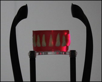
The processed extracted teeth conforming to the requirements specified above were fixed on dental wax, with the labial side of the crown facing outward and the lingual side close to the wax; a distance of 5 mm between each of the teeth was left, and an arch form was constructed as the scanning model ( Fig 1 ).
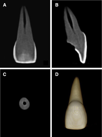
CBCT images were obtained using the Kodak 9000C 3D (Kodak Dental Systems, Carestream Health, Rochester, NY), with visual range of 50 × 37 mm, tube voltage of 70 kV, tube current of 5.2 mA, slice thickness of 0.076 mm, and scanning time of 10 seconds. After the scanning and overlapping processes, the final image resolution was 0.076 mm. The images were saved in DICOM file format and imported into the Ez Implant computer software (version 1.5; Vatech, Hwaseong-si, Gyeonggi-do, Korea) for 3D image reconstruction ( Fig 2 ). Multiplanar reconstruction view mode was chosen in the software so that the tissue layers of the teeth, such as the surface of the enamel and the cementum, could be clearly shown. After the median sagittal tomographic images were obtained, they were resized to a uniform enlarged scale of 2 cm and saved in bitmap format ( Fig 3 , A ).
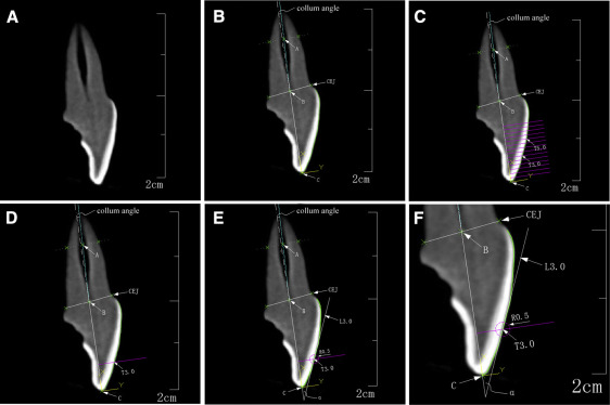
For the convenience of the study, the specific points, lines, and angles of each tooth’s median sagittal section were defined as follows ( Figs 3 and 4 ). “CEJ” indicated the labial or lingual cementoenamel junction. “A” was the midpoint of the junction of the middle and apical thirds of the root. “B” was the midpoint between labial and lingual cementoenamel junctions. “C” represented the midpoint of the incisal edge or cusp tip of the tooth. “T” was a tangent point on the labial surface of the crown.
“BC” was the straight line connecting points B and C, representing the long axis of the crown. “AB” was the straight line connecting points A and B, representing the long axis of the root. “L” was a tangent line on the labial surface of the crown through point T. On line BC, 4 points were located, at distances of 3.5, 4.0, 4.5, and 5.0 mm from point C, through which 4 perpendicular lines were constructed. The intersections between the perpendicular lines and the labial surface were, respectively, called “T3.5,” “T4.0,” “T4.5,” and “T5.0.” The tangent lines through T3.5, T4.0, T4.5, and T5.0 were called “L3.5,” “L4.0,” “L4.5,” and “L5.0,” respectively ( Fig 3 , C – E ).
“Collum angle” was the angle between lines BC and AB. When line AB was on the lingual side of line BC, the collum angle was defined as a positive value; otherwise, it was defined as a negative value. “α” was the angle of intersection between lines L and BC. The angle between L3.5 (or L4.0, L4.5, and L5.0) and line BC was called α3.5 (or α4.0, α4.5, and α5.0) ( Fig 3 , B and E ).
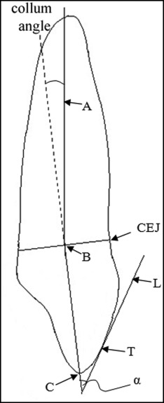
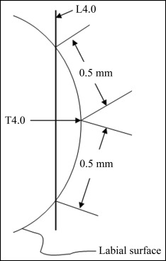
To ensure that the tangent lines (L3.5, L4.0, L4.5, and L5.0) were more objective and repetitive, 2 points were plotted at a distance of 0.5 mm from the tangent point (T3.5, T4.0, T4.5, or T5.0) separately toward the occlusal and gingival sides. The straight line through these 2 points represented the direction of the tangent lines ( Fig 3 , E and F ). Taking T4.0 for example, a schematic diagram was created to show how to determine the direction of the tangent line ( Fig 5 ).
The images were imported into the AutoCAD software at a scale of 2 cm = 2000 coordinate units ( Fig 3 ). Measuring the indexes on the images with the methods designed, each image needed to record 11 coordinate points. The collum angle and angle α, corresponding to different heights (3.5, 4.0, 4.5, and 5.0 mm) of each tooth, were determined using the certain coordinates.
Statistical analysis
Data were expressed as the means and standard deviations and were analyzed using SPSS statistical software (version 13.0; SPSS, Chicago, Ill), to compare the differences among α3.5, α4.0, α4.5, and α5.0 of the teeth and the differences between the collum angle and 0° by 1-factor analysis of variance, the Student-Newman-Keuls multiple comparison procedure, and the 1-sample t test. The level of statistical significance was set at 0.05.
Results
The mean values of angle α at different heights of the maxillary anterior teeth are shown in Table I . There were statistically significant differences among the mean values of angle α for the maxillary central incisors, lateral incisors, and canines ( P <0.001) and between any 2 groups among α3.5, α4.0, α4.5, and α5.0 of the teeth ( P <0.05). The mean values of angle α for the central incisors decreased by 4.25° between 3.5 and 5.0 mm from the incisor edge. In addition, they decreased by approximately 1.5° as the height increased every 0.5 mm. For the maxillary lateral incisors and canines, between 3.5 and 5.0 mm from the incisor edge, the mean values of angle α decreased by 6.05° and 5.44°, respectively. The mean values of angle α decreased by approximately 2.0° when the height increased every 0.5 mm for the maxillary lateral incisors and canines.
x ¯ ± s
)
Stay updated, free dental videos. Join our Telegram channel
VIDEdental - Online dental courses


