Treatment of an impacted maxillary central incisor poses a unique challenge to the orthodontist because of its position within the esthetic zone, requiring careful management of the soft tissues and an effective biomechanical setup for alignment. This article describes a novel method of extending an extrusion wire from cross tubes attached on the base archwire for forced eruption of impacted central incisors. The effectiveness and versatility of this method are demonstrated with 2 patients.
Impaction of the maxillary central incisors occurs frequently in the population, nearly as commonly as impacted maxillary canines. Normal eruption of the central incisor typically occurs between 8 and 10 years of age. Any delay in eruption can have a potential impact on the eruption of other anterior teeth (eg, the maxillary canines) and can also result in space loss and midline deviation. The 2 primary causes of impaction are trauma to the deciduous central incisor resulting in a developmental disturbance of the tooth bud and mechanical obstruction in the path of eruption caused by a supernumerary tooth or odontoma. Treatment of an impacted central incisor requires a multidisciplinary approach, with periodontal surgical exposure followed by orthodontic forced eruption.
Orthodontic extrusion of impacted teeth has classically been managed using elastomeric chains or threads, nickel-titanium overlays, cantilevers, and extrusion arches. Because of force decay, elastomerics do not deliver a continuous force to the tooth over the treatment period and might be less efficient. Placement of a continuous flexible wire, such as a nickel-titanium wire, can be used to deliver a constant force but can lead to side effects, with reciprocal intrusion of the adjacent teeth. A nickel-titanium overlay or “piggy-back” wire enables application of a constant force while also minimizing side effects with a rigid stainless steel base archwire, for example. However, the rate of movement can be affected by the friction on the adjacent ligated brackets, thereby further slowing the process. In addition, it can be a challenge to titrate the force level exerted. Cantilevers and extrusion arches can offer further benefits with the delivery of a continuous force with minimal friction, since they are not ligated to adjacent teeth. In addition, the forces can be measured and well controlled because the device is anchored to a rigid base arch. A particular challenge of using cantilevers and extrusion arches for impacted incisors specifically is in determining the anchor position, which often needs to pass the canine curvature. This typically leads to bowing of the auxiliary wire and patient discomfort.
Here, we describe an efficient and comfortable design for extruding impacted central incisors using a cross-tube extrusion arch. Two patients are presented to illustrate the basic framework and method of activation as well as creative ways to use this clinical setup for controlling the vector of eruption and applying torque.
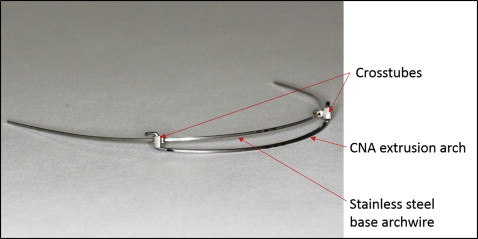
The cross-tube extrusion wire has 2 cross tubes, 2 mm wide (Ortho Technology, Tampa, Fla), placed through the base 0.019 × 0.025-in stainless steel archwire ( Fig 1 ). The cross tube consists of 2 tubes, 0.022 × 0.028 in, soldered at 90° to each other, so that a wire can be inserted both horizontally and vertically. The cross tubes are crimped mesial to the canines and can also be welded in place to prevent sliding along the arch. A 0.017 × 0.025-in CNA beta-titanium wire (Ortho Organizers, Carlsbad, Calif) is used to apply a consistent extrusive force that can be titrated. The distance between the cross tubes is then measured, and 90° bends are placed in the CNA wire at the specified distance, so that the auxiliary wire can be placed into the vertical component of the cross tubes. Once in place in the cross tubes, the ends are cinched, and the setup is placed in the patient’s mouth in this inactivated or passive state. Then the activated extrusion wire is drawn toward the labial vestibule and ligated to the bonded attachment or exposed chain with steel ligatures or thread.
Patient 1
A 15-year-old postpubertal girl in the permanent dentition came with a chief complaint of an unerupted maxillary right central incisor ( Fig 2 , A ). Her previous medical and dental histories were nonincidental. A Class I occlusion with minimal overjet and overbite was noted. The crown of the maxillary right central incisor was palpable in the labial vestibule, above the mucogingival junction. A periapical radiograph ( Fig 2 , B ) indicated a radiopaque mass in the path of eruption of the right central incisor consistent with a compound odontoma. The orthodontic plan was to treat the patient without extractions and to use the closed surgical exposure method followed by orthodontic traction to erupt the impacted incisor.
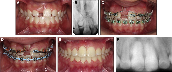
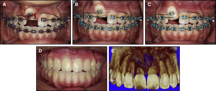
The patient was bonded using 0.022 × 0.028-in twin brackets (Ortho Organizers) with a McLaughlin-Bennett-Trevisi (MBT) prescription. During the leveling and aligning stage, the patient was referred to an oral surgeon for an excisional biopsy of the compound odontoma, closed surgical exposure, and bonding of a traction hook on the impacted central incisor. Once the remaining dentition was aligned on 0.019 × 0.025-in stainless steel archwires and space was developed for the right central incisor, the cross-tube extrusion arch assembly was placed ( Fig 2 , C ). With a force gauge, 80 to 100 g of force was applied, and the extrusion arch was ligated to the gold chain with ligature wire. The incisor erupted through the attached gingiva within 4 months ( Fig 2 , D ). At the time of debond, a minimal gingival height discrepancy was noted ( Fig 2 , E ), and some root resorption was seen on the panoramic radiograph ( Fig 2 , F ).
Patient 2
A 12-year-old pubertal girl came with a chief complaint of maxillary incisor crowding. Her previous medical and dental histories were nonincidental.
The pretreatment facial examination showed a mesofacial pattern with a concave soft-tissue profile caused by a prognathic mandible and a high mandibular plane angle. The patient had 100% maxillary incisor display on smiling. The maxillary midline was shifted to the right by 2 mm, and the mandibular dental midline was coincident with the facial midline.
The intraoral examination indicated a full complement of teeth except for the maxillary right central incisor and left canine. The maxillary anterior teeth were in crossbite ( Fig 3 , A ). The mandibular arch was well aligned with mild crowding. Minimal overbite was noted with 1 mm of negative overjet. The molars were in a half-cusp Class III relationship with a bilateral posterior crossbite. The radiographic examination showed that the maxillary right central incisor was horizontally impacted and inclined toward the maxillary left central incisor, which had a dilacerated root ( Fig 3 , B ). Whereas surgical treatment is planned once the patient completes growth, phase 1 therapy was initiated for the correction of the transverse discrepancy and alignment of the impacted central incisor.
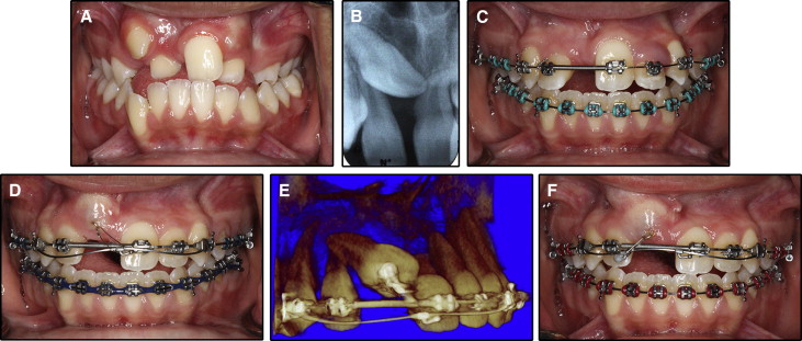
After rapid maxillary expansion with a hyrax appliance, the patient was bonded with 0.022 × 0.028-in twin brackets (3M Unitek, Monrovia, Calif) with an MBT prescription, and the remaining dentition was aligned on 0.019 × 0.025-in stainless steel archwires. The central incisor space was developed using a nickel-titanium coil spring ( Fig 3 , C ). To align the impacted central incisor, a closed exposure method was again used with the traction hook bonded on the labial surface of the impacted incisor and the full-thickness flap repositioned.
Alignment of the impacted central incisor was planned in 3 phases. In the first phase, the line of force was directed along the long axis of the tooth (ie, mesial, incisal, and labial direction). It was accomplished with an archwire hook crimped mesial to the long axis of the tooth ( Fig 3 , D ). Once the crown of the incisor reached the alveolar crest, a small volume cone-beam computed tomography image was taken to evaluate the extent of extrusion and localize the tooth position. This showed that the impacted central incisor had extruded and was approximating the crown of the left central incisor ( Fig 3 , E ). In addition, there was dilaceration of the right central incisor root, with the root tip curved palatally on the axial sections. To achieve uncontrolled tipping and move the crown in a lateral direction, a second archwire hook was crimped on the extrusion arch adjacent to the maxillary right lateral incisor region and ligated to the bonded attachment ( Fig 3 , F ).
For the final phase, palatal root torque was required. The central incisor was bonded with a twin bracket, and the cross-tube extrusion arch was repositioned in the gingival direction. The auxiliary archwire started with a 0.016-in CNA wire ( Fig 4 , A ) and was sequentially upgraded to a 0.019 × 0.025-in CNA wire ( Fig 4 , B and C ). Significant mesiodistal correction and palatal root torque were achieved. The patient was then debonded and placed in retention until the completion of growth and reevaluation for the start of presurgical orthodontics ( Fig 4 , D ). Root resorption was noted both apically and on the palatal extension of the dilacerated root ( Fig 4 , E ).