Introduction
It has been found that controlled movement of the anterior teeth can be obtained by attaching a certain length of power arm onto an archwire in sliding mechanics. However, the impact of the archwire/bracket play on anterior tooth movement has not been clarified. The purpose of this study was to compare the effect of the power arm on anterior tooth movements with different dimensions of bracket slots and archwires.
Methods
A 3-dimensional finite element method was used to simulate en-masse anterior tooth retraction in sliding mechanics. Displacements of the maxillary central incisor and the archwire deformation were calculated when applying retraction forces from different lengths of power arms.
Results
When a 0.017 × 0.022-in archwire was engaged into the 0.018-in slot bracket, bodily movement of the incisor was obtained with 9.1-mm length of the power arm. When a 0.022-in slot system was coupled with a 0.019 × 0.025-in archwire, bodily movement was observed with a power arm length of 11.6 mm.
Conclusions
Archwire/bracket play has a remarkable impact on anterior tooth movement. An effective torque application to the anterior teeth becomes clinically difficult in sliding mechanics combined with power arms when the archwire/bracket play is large.
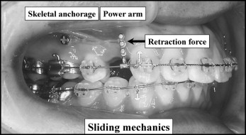
The demand for speedy, effective, and accurate orthodontic treatment systems has increased to shorten the treatment period. Accordingly, the use of implant anchorage in sliding mechanics has become more common all around the world. In addition to this system, sliding mechanics with the combined use of power arms has gradually been applied for obtaining controlled anterior tooth movements during space closure ( Fig 1 ). That is, the desired type of anterior tooth movement, such as lingual crown tipping, bodily movement, or lingual root tipping, can be easily achieved by attaching various lengths of power arms onto an archwire in sliding mechanics.
Several studies have been carried out to investigate various biomechanical factors affecting tooth movement in sliding mechanics, such as the flexural rigidity of the archwire, friction, and height of the retraction force. However, optimal loading conditions for controlled movement of anterior teeth in sliding mechanics combined with power arms are not fully understood. A few attempts with the finite element (FE) method have been reported on tooth displacement when a single canine retraction or an en-masse retraction is performed in sliding mechanics. In those studies, spring elements are used between a tooth and an archwire instead of friction between the surface of a bracket slot and an archwire. Therefore, the mechanical condition is not sufficiently accurate to approximate an actual clinical situation. To our knowledge, there are only 2 studies that simulate en-masse retraction when brackets were modeled and a coefficient of friction was given to the interface between bracket slots and an archwire including contact-sliding problems. It was found that the anterior tooth movement varied depending on the amount of archwire/bracket play. However, the effect of play on anterior tooth movement has not been fully understood; clinicians must consider this in an actual clinical situation for any treatment step in sliding mechanics.
The purpose of this study was to clarify the effect of the bracket slot and archwire dimensions on anterior tooth movement during space closure in sliding mechanics by means of a 3-dimensional (3D) FE model.
Material and methods
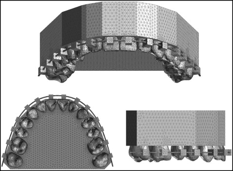
The construction method of the 3D FE model has been described previously. Computed tomography images of the 14 maxillary teeth, taken with a multi-image cone-beam computed tomography scanner (3DX; J. Morita, Kyoto, Japan), were saved as DICOM data and exported to 3D image processing and editing software (Mimics 10.02; Materialize Software, Leuven, Belgium). The 3D solid model was created and converted to a 3D FE model using FE analysis preprocess and postprocess software (Patran 2008r1; MSC Software, Los Angeles, Calif). Each 3D FE model for the periodontal ligament (PDL), alveolar bone, bracket, archwire, and power arm was separately constructed using the same software. The PDL had a uniform thickness of 0.2 mm. The bracket height of the maxillary central incisor was placed according to a prescription, which was 4.5 mm in height from the incisal edge of the tooth. Two 3D solid models were constructed. One had the combination of brackets with a 0.018 × 0.025-in slot and a 0.017 × 0.022-in stainless steel archwire, and the other had 0.022 × 0.028-in slot brackets and a 0.019 × 0.025-in archwire. Based on these 3D solid models, an FE mesh was created to make a node-to-node connection between tooth, PDL, and alveolar bone. An FE mesh of the archwire was created separately from the bracket to allow the archwire to slide through the bracket slots. The 3D FE model consisted of 423,772 isoparametric tetrahedral solid elements (10 noded) and 83,790 nodes, or 432,356 elements and 85,957 nodes ( Fig 2 ).
The material parameters used in this study are represented in the Table . To simplify the model and reduce the time for analysis, the same properties were given to the archwires, power arms, and brackets. Other structures such as teeth, alveolar bone, and PDL were modeled as homogenous and isotropic for the same reason.
| Material | Young’s modulus (MPa) | Poisson’s ratio |
|---|---|---|
| Tooth | 20000 | 0.30 |
| PDL | 0.05 | 0.30 |
| Alveolar bone | 2000 | 0.30 |
| Archwire/power arm/bracket | 200000 | 0.30 |
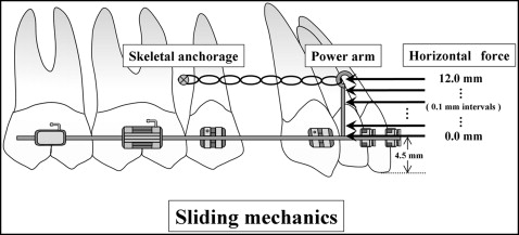
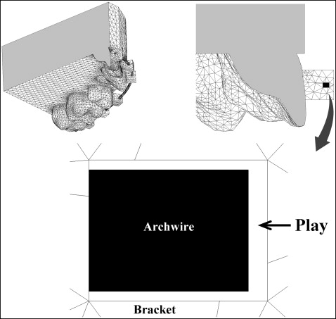
Assuming that the case model was diagnosed as maxillary protrusion, bilateral maxillary first premolar extractions were indicated. The model included 12 teeth, and 2 skeletal anchorages (miniscrews or miniplate implants) were inserted at both sides of the buccal region between the second premolar and the first molar. Two power arms were attached onto an archwire bilaterally at the segment between the lateral incisor and the canine, and these lengths were changed from 0 to 12 mm with 0.1-mm intervals from the bracket slot level ( Fig 3 ). The horizontal retraction force of 1.5 N was applied from the implant anchorage to the power arm on both sides. The model was restrained in 6° of freedom at the bottom of the alveolar bone. The coefficient of friction between the bracket slots and the archwire was assumed to be 0.2. A cross-sectional view indicating the boundary between the bracket and the archwire is shown in Figure 4 . The archwire was horizontally positioned to contact the bottom surface of the bracket slots and vertically in the middle of the bracket. Under these conditions, 3D FE analysis was performed using a 3D FE program (Marc; MSC Software). We analyzed how the archwire was deformed and, consequently, how the maxillary central incisor moved. Then we compared the results obtained with the 0.017 × 0.022-in stainless steel archwire in the 0.018-in slot and the 0.019 × 0.025-in archwire in the 0.022-in slot.
Results
The relationship between the degree of labiolingual tipping of the maxillary central incisor and the height of retraction force on the power arm is shown in Figure 5 . If the 0.017 × 0.022-in stainless steel archwire was engaged into the 0.018-in slot brackets as shown by a solid line in Figure 5 , lingual crown tipping of the maxillary central incisor was observed when the retraction force was applied at 0 mm, which corresponds to the bracket slot level. The direction of tooth rotation changed from lingual crown tipping to lingual root tipping as the level of the retraction force on the power arm was moved apically from the bracket slot level. At the height of 9.1 mm, no rotation was observed; ie, bodily movement occurred. Lingual root tipping of the incisor was produced when the retraction force was set above 9.1 mm. When the 0.022-in slot bracket system was combined with the 0.019 × 0.025-in archwire, bodily movement of the incisor was achieved at the height level of the retraction force of 11.6 mm as shown by a dotted line in Figure 5 , although the rotational endency was the same as the 0.018-in slot system.
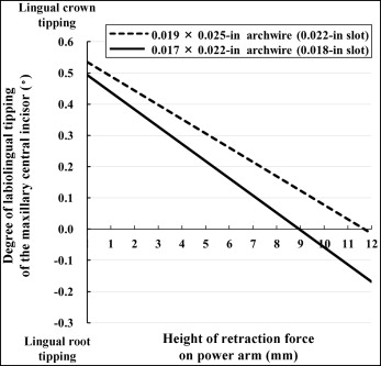
Figure 6 shows the loading conditions under which controlled anterior tooth movements, such as controlled lingual root tipping, bodily movement, and controlled lingual crown tipping, can be achieved. Controlled lingual root tipping is defined as the type of tooth movement in which the tooth tips around its incisal edge as the center of rotation. On the other hand, controlled lingual crown tipping indicates the movement in which the tooth tips around its root apex as the center of rotation.
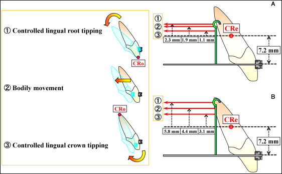
If the 0.017 × 0.022-in archwire was used in a 0.018-in slot, controlled lingual root tipping was carried out at the height of the retraction force of 9.5 mm, which was 2.3 mm higher than the level of the center of resistance. At a height of 9.1 mm, bodily movement was achieved. Controlled lingual crown tipping was observed at the 8.3-mm height of retraction force level ( Fig 6 , A ).
When the 0.019 × 0.025-in archwire was used in the 0.022-in slot, controlled lingual root tipping was obtained at the height of 13.0 mm. Bodily movement was produced at an 11.6-mm height of retraction force. Controlled lingual crown tipping occurred at a level of 10.3-mm height ( Fig 6 , B ).
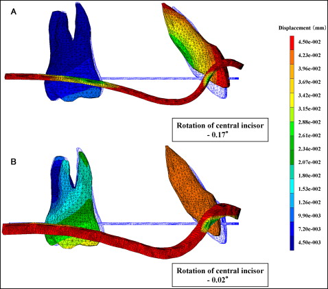
The deformation of the archwire and the resultant displacement of the maxillary central incisor and first molar after the application of retraction force at the level of 12 mm are shown in Figure 7 . For a better understanding of the deformation of the archwire and the tooth displacement, these displacements were magnified 50 times, and the displacements of the central incisor were focused on. The tooth and the archwire in blue show the initial positions.
Stay updated, free dental videos. Join our Telegram channel
VIDEdental - Online dental courses


