Introduction
Our objective was to enable accurate miniscrew placement after preoperative simulation. We developed a new template for miniscrew placement and evaluated its accuracy.
Methods
Eleven patients who had bimaxillary protrusion were scanned with computed tomography. The 3-dimensional computed tomography data were used to produce, with stereolithography apparatus, a template for accurate miniscrew placement. The interradicular space available for miniscrew placement was calculated in the 3-dimensional images. Postoperative computed tomography images were matched with preoperative images to calculate the deviations between the planned and actual placements.
Results
The distance for placement of a miniscrew between 2 roots was 4.12 mm (SD, 0.25 mm; range, 3.7-4.5 mm). The placed miniscrews showed an average angular deviation of 1.2° (SD, 0.43°; range, 0.6°-2.41°) compared with the plan, whereas the mean linear distomesial deviation was 0.42 mm (SD, 0.13 mm; range, 0.15-0.6 mm) at the tip.
Conclusions
The proposed template has high accuracy and will be especially useful for patients who require precise miniscrew placement.
Miniscrews have been used for absolute anchorage in orthodontics for a long time. Miniscrews are always placed in alveolar bone between the first molar and the second premolar, and the placement angle is always 30° (the long axis of the miniscrew and the tooth axis) in the maxilla and 20° in the mandible. However, the high failure rates of miniscrews troubles orthodontists. According to previous articles, the rates of failure are about 11% to 30.4%. Placing a miniscrew in the limited space between the roots of the second premolar and the first molar causes some risk of injury to important anatomic structures. Safe and optimal miniscrew stabilization requires ideal placement point and trajectory. Improper screw placement can lead to neurovascular damage or suboptimal biomechanical stabilization. To achieve precise and safe placement of miniscrews in interradicular sites, several methods have been developed, but they cannot guarantee precise placement. A controllable method for miniscrew placement and direction is important for orthodontists.
Computed tomography (CT), 3-dimensional (3D) software, and stereolithography apparatus (SLA) (Xi’an Jiaotong University, Xi’an, China) have been widely used in oral medicine. CT has been used for measurement of interradicular space for miniscrews and assessment of their position. The 3D software helps to render objects from the CT images for diagnosis and treatment planning. Computer-aided design and computer-aided manufacturing (CAD/CAM) technology has been used in dental restorations and implantology. The CAD/CAM template for implants has been accepted and used widely, and gives us another method to aid in achieving controllable miniscrew placement. In this article, the CAD/CAM template for orthodontic miniscrews is introduced, and its accuracy is assessed.
Material and methods
Materialise’s interactive medical image control system (MIMICS) and Magics (both, Materialise, Leuven, Belgium) are both widely used medical software programs. The miniscrew template described in this article was designed with these tools.
MIMICS is an interactive tool for the visualization and segmentation of CT and magnetic resonance images and the 3D rendering of objects. Therefore, in medicine, MIMICS can be used for diagnosis, operation planning, and rehearsal purposes. A flexible interface to rapid prototyping systems is included for building distinctive segmentation objects. Magics is companion software to MIMICS; the user can further process the 3D model (stereolithography [STL] file) that is created in MIMICS.
Stereolithography apparatus (SLA) is the process of using photosensitive resins cured by a laser that traces the parts across sectional geometry layer by layer. SLA produces accurate models with various materials. We used a resin (SOMOS 11120 photosensitive resin, DSM, Elgin, IL).
Eleven patients with bimaxillary protrusion agreed to have their 4 first premolars extracted; 34 miniscrews (Beici Medical Company, Ningbo, China; Fig 1 ) were planned to provide absolute anchorage. The miniscrews were placed in the interradicular area between the second premolar and the first molar. Six patients received 4 miniscrews, and 5 patients had miniscrews placed in the maxilla only.

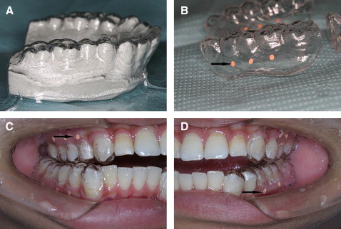
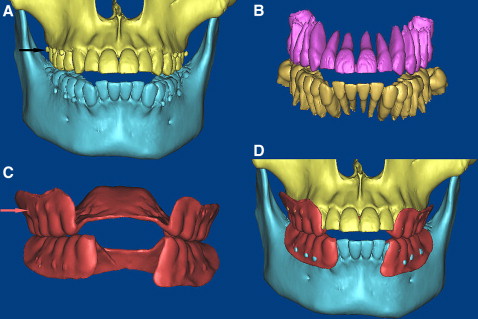
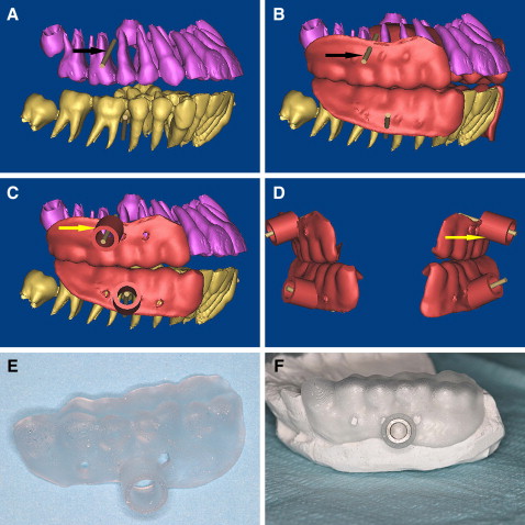
The CAD/CAM template for the miniscrews in this study was designed based on the CT data and fabricated by the SLA. After preparing mounted diagnostic casts with fully extended vestibular borders of the jaws, the radiographic templates were fabricated with the vacuum-formed technique ( Fig 2 ), and the patients and the radiographic template were scanned before the procedure with the double-scan technique (the first scan is of the patient with the radiographic template in place, and the second scan is of the radiographic template only). The 3D virtual models of the teeth and the 2 jaws were reconstructed based on the CT data in the MIMICS software ( Fig 3 , A-C ) by superimposing the 2 sets of scans (the osseous tissues and the radiographic template) with radiographic markers as reference points ( Fig 3 , D ). The virtual miniscrews were placed in safe and optimal positions when the roots of teeth were visualized ( Fig 4 , A ), and the placement site and angle were determined. The drill template was designed with the radiographic guide and the 3D information of the planned drill paths ( Fig 4 , B-D ), and the stereolithography template was fabricated with a CAD/CAM procedure (the rapid prototyping [RP] apparatus was manufactured by Xi’an Jiaotong University); the template is shown in Figure 4 , E . To improve the intensity of the template, the positioning sleeves were cemented in the surgical template ( Fig 4 , F ). When the bone-teeth and radiographic templates were reconstructed, the thresholds were chosen carefully, and the thickness of the radiographic template was compared with the stereolithography one to assess the reliability of the threshold and the accuracy of the RP.
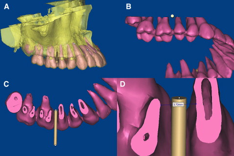
When the 3D models of the teeth and the 2 jaws were reconstructed, we evaluated the osseous tissues in relation to the position of the teeth by merging the independent data, and the virtual miniscrews (cylinders) were placed in the ideal position (proper placement site and orientation). When the position for the miniscrew was determined ( Fig 5 , A ), a plane was created along the cylinder ( Fig 5 , B ). The distance between the 2 roots for the miniscrew was measured. At this plane, the minimum distance between the 2 roots was measured. As we know, the periodontal ligament is about 0.15 to 0.38 mm thick on average, and the diameter of the miniscrew in this study was 1.6 mm. The virtual screw was placed in the midline of the 2 roots, and the safe deviation for the miniscrew could be calculated by the formula, C = A/2 – B – 0.4 mm, where A is the interradicular distance, B is the radius of the miniscrew, and C is the safe deviation. The periodontal ligament was assumed to be 0.4 mm thick in this study for safe placement. Thus, the allowed deviation for the miniscrew was obtained and used as the control for assessment of the accuracy of the template.
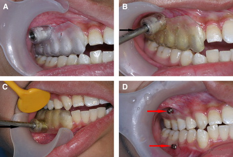
After a local anesthetic was given, the surgical template was placed intraorally. The seating of the template should be confirmed, and the surgical template should be held in place by the patient’s bite force. Once it was seated, the patient was asked to bite the template to expose the surgical sites of the guide; then the self-drilling miniscrews were placed with a screwdriver ( Fig 6 ).
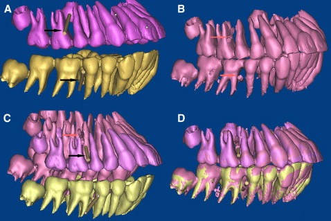
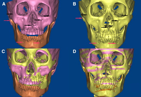
The surgical procedures were performed uneventfully, and the patients were scanned with CT again. The postoperative 3D models of the teeth, maxillae, mandibles, and miniscrews were reconstructed and registered with the preoperative 3D models by using the same anatomic sites as landmark points ( Fig 7 ). The point registration easily moved an STL image to a certain location. This was done by placing 4 sets of landmark points on the STL images, 3D objects, and images. MIMICS then calculated the transformation matrix for the best fit between the start and end points and applied that transformation matrix on the selected STL images. Because of the radiographic template on the occucal surface, the mandible’s position on the before and after CT images was different, so the mandible and maxilla must be registered separately ( Fig 7 ). After point registration, the STL registration was performed to register STL images on masks to improve the accuracy of registration. Registrations were performed 3 times in 2 weeks, and we chose the best one for measurements of this study ( Fig 8 ).
To measure the deviation of the center position of the miniscrews from the planned position (cylinders) in 3 dimensions, the new 3D coordinate was adjusted and defined at the apex of the virtual miniscrew in Magics ( Fig 9 ). The x, y, and z axes were defined: the x-axis represents the distomesial position, the y-axis represents the vertical position, and the z-axis represents the buccopalatal position. The 3D deviation of the actual miniscrew was calculated at the apex and the placement site ( Fig 9 ). The x, y, and z values at the apex represented the deviation of the actual miniscrew. In this way, the deviation was evaluated in 3 directions, and the distomesial position (x-axis) was more important for the security of the miniscrew. In this study, we mainly focused on assessing this axis. As for angle deviations, they were hard to evaluate, since the angle between the actual miniscrew and the simulated one showed a twisted relationship. Therefore, in this study, both central axes were projected to the mesiodistal axis, and the deviation of the angle between them was calculated with the formula, = tan – 1 (b – a)/c, where a is the deviation at the tail, b is the deviation at the head, and c is the length of the miniscrew in the bone. At the placement sites, there was little deviation, so the deviation there was measured with linear CT measurements instead of 3D assessment.

