Introduction
The purpose of this study was to develop a methodology to measure the mesiodistal angulation and the faciolingual inclination of each whole tooth (including the root) by using 3-dimensional volumetric images generated from cone-beam computed tomography scans.
Methods
A plastic typodont with 28 teeth in ideal occlusion was fixed in position in a dry human skull. Stainless steel balls were fixed to the occlusal centers of the crowns and to the apices or bifurcation or trifurcation centers of the roots. Cone-beam computed tomography images were taken and rendered in Dolphin 3D (Dolphin, Chatsworth, Calif). The University of Southern California root vector analysis program was developed and customized to digitize the crown and root centers that define the long axis of each whole tooth. Special algorithms were used to automatically calculate the mesiodistal angulation and the faciolingual inclination of each whole tooth. Angulation measurements repeated 5 times by using this new method were compared with the true values from the coordinate measuring machine measurements. Next, the root points of 8 selected typodont teeth were modified to generate known angulation and inclination values, and 5-time repeated measurements of these teeth were compared with the known values.
Results
Intraclass correlation coefficients for the repeated mesiodistal angulation and faciolingual inclination measurements were close to 1. Comparisons between our 5-time repeated angulation measurements and the coordinate measuring machine’s true angulation values showed 5 teeth with statistically significant differences. However, only the maxillary right lateral incisor showed a mean difference that might exceed 2.5° for clinical significance. Comparisons between the 5-repeated measurements of 8 teeth with known mesiodistal angulation and faciolingual inclination values showed no statistically significant differences between the measured and the known values, and no measurement had a 95% confidence interval beyond 1°.
Conclusions
We have developed the novel University of Southern California root vector analysis program to accurately measure each whole tooth mesiodistal angulation and faciolingual inclination, in a clinically significant level, directly from the cone-beam computed tomography volumetric images.
The basic objectives of orthodontic treatment are to obtain proper positions of all teeth by using various orthodontic appliances, to form a functional and stable occlusion, and to display the teeth in proper relationships to one another and in harmony with the maxillofacial hard and soft tissues after treatment. Six parameters describe each tooth location in 3-dimensional space. Three are positional (mesiodistal, faciolingual, and occlusogingival), and 3 are angular (mesiodistal angulation, faciolingual inclination, and axial rotation). Nearly half a century ago, Andrews studied 120 patients with optimal occlusions and obtained the positional and angular norms for all teeth by measuring their crowns on the study models. Various types of preadjusted appliances that are used by most orthodontists today are, to a certain degree, derived from the original straight-wire appliances he developed based on these crown norms. However, although 4 of the 6 parameters defining tooth positions are dictated by the crowns and are easy to monitor clinically, later research has shown that crowns might not provide clear indications for the angulation and the inclination of the whole teeth, including the roots. Moreover, straight-wire techniques rely heavily on precise bracket positioning during initial bonding, and yet orthodontists at various experience levels have found difficulties in accurately placing brackets directly on patients’ teeth or even indirectly on the teeth of stone models. So far, the roots that constitute about half of the whole tooth have been mostly ignored. It is speculated that the roots might also need to be assessed to achieve ideal whole tooth angulation and inclination.
Traditionally, panoramic x-rays have been used at the initial, progress, and finishing stages of orthodontic treatment to diagnose, monitor, and finalize the angulations of the teeth. However, studies have indicated that panoramic x-rays have distortions and do not reflect the true 3-dimensional teeth angulations because the x-ray beam is not always orthogonal to the target teeth. For faciolingual inclinations, the only assessment tool available is the lateral cephalogram for the maxillary and mandibular central incisors. A posteroanterior cephalogram might capture the faciolingual inclinations of a few molars, but the image quality is usually poor and rarely used.
As we know, the position of teeth is a 3-dimensional issue. Andrews did not measure the angulation and the inclination of teeth from 2-dimensional x-rays but from study models that are 3-dimensional. Fortunately, the development and use of cone-beam computed tomography (CBCT) in orthodontics in recent years have allowed us see the roots of teeth in 3 dimensions as well. This lets us accurately evaluate the mesiodistal angulation and the faciolingual inclination of each whole tooth (crown and root) rather than just the crown. However, there is no clinically useful tool currently available to systemically measure whole tooth angulation and inclination in 3 dimensions. Van Elslande et al had to construct 2-dimensional panoramic-like images from 3-dimensional CBCT images to measure the angulation of the typodont teeth. They compared these measurements with those taken directly from a coordinate measuring machine, the gold standard 3-dimensional measuring device. They suggested that the constructed images might be better than conventional panoramic radiographs in assessing root angulations, although the measurements were still off significantly from the true 3-dimensional coordinate measuring machine’s measurements for a few teeth. The coordinate measuring machine was also used in an earlier study by Garcia-Figueroa et al to show the effect of changing the faciolingual inclination of a few selected teeth on their mesiodistal angulation measurements. However, the gold standard coordinate measuring machine cannot be used on patients, since the tip of the machine’s probe cannot be brought in contact with the patients’ root apices.
We have collaborated with the Dolphin company (Chatsworth, Calif) and developed the University of Southern California (USC) root vector analysis program in the Dolphin 3D module to directly measure the mesiodistal angulation and the faciolingual inclination of each whole tooth using CBCT volumetric images. To test the validity of our methodology, we also collaborated with the research group from the University of Alberta, Edmonton, Alberta, Canada, who provided the typodont CBCT images and the coordinate measuring machine’s mesiodistal angulation measurement data for the typodont teeth to compare with our results.
Material and methods
We measured the mesiodistal angulation of the typodont teeth with the coordinate measuring machine (Faro International, Lake Mary, Fla). The typodont was based on a modification of the model previously reported by McKee et al and Garcia-Figueroa et al. It consisted of transparent plastic anatomic typodont maxilla and mandible (Kilgore International, Coldwater, Mich) with synthetic teeth in idealized occlusion from the second molar to the second molar. As shown by Van Elslande et al, the typodont was mounted on a dry human skull. Stainless steel balls (Small Parts, Miramar, Fla), 1.58 mm in diameter, were placed at the approximate mesiodistal and faciolingual centers of the occlusal surfaces, and at the approximate centers of the root apices for single-rooted teeth or the centers of the bifurcation or trifurcation at the level of the root apices for multi-rooted teeth. A line connecting the 2 centers on each tooth represented its long axis.
The coordinate measuring machine was used to determine the actual mesiodistal angular measurement of each whole tooth with reference to the archwires that were held in place on the plastic molds of the maxilla and the mandible at approximately the middle of the roots. A mesiodistal plane was created for each tooth that was perpendicular to the horizontal (archwire) plane. This tooth-specific reference plane passed through the mesial and distal interproximal points marked on the archwires with crimpable stops. The mesiodistal angulation of a tooth was the measurement of the angulation between the projection of the tooth’s long axis on the mesiodistal plane and the vertical line.
One investigator (D.V.E.) made repeated measurements on 5 separate occasions, 5 days apart, and the intraclass correlation coefficient values were calculated to determine the reliability of the coordinate measuring machine’s angulation measurements. The coordinate measuring machine was reported by the manufacturer to be accurate to within 0.013 mm. For angular measurements, the machine was found to be accurate to within 0.031°. The average of the 5-time repeated coordinate measuring machine’s angulation measurements were used as the true values.
The typodont teeth’s mesiodistal angulations and faciolingual inclinations were also measured by using the custom USC root vector analysis program. For the CBCT scan of the same typodont used above, a NewTom 3G volume scanner (AFP, Elmsford, NY) was used according to the manufacturer’s instructions as shown also by Van Elslande et al. Twenty-five independent images were obtained from separate CBCT scans for the previous study, and 5 of them were randomly selected and imported into the Dolphin Imaging 3D program. The USC root vector analysis program was developed in the Dolphin 3D module to measure both the mesiodistal angulation and the faciolingual inclination of each whole tooth as shown below.
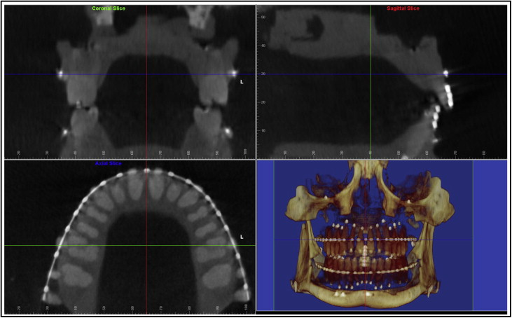
Once the typodont digital imaging and communications in medicine (DICOM) data were imported into Dolphin 3D, a 3-dimensional global coordinate system was first generated for the proper orientation of the head and the maxillofacial structures. This coordinate system included the midsagittal plane, the coronal plane, and the axial plane, each perpendicular to the other 2 planes ( Fig 1 ). The midsagittal plane evenly divided the right and the left halves of the skull; the coronal plane passed through the maxillary first molar buccal grooves on both sides, and the axial plane was the archwire plane. Since the maxillary and mandibular teeth had separate archwire planes, there were also 2 separate 3-dimensional global coordinates: 1 saved for the maxilla, and 1 saved for the mandible.
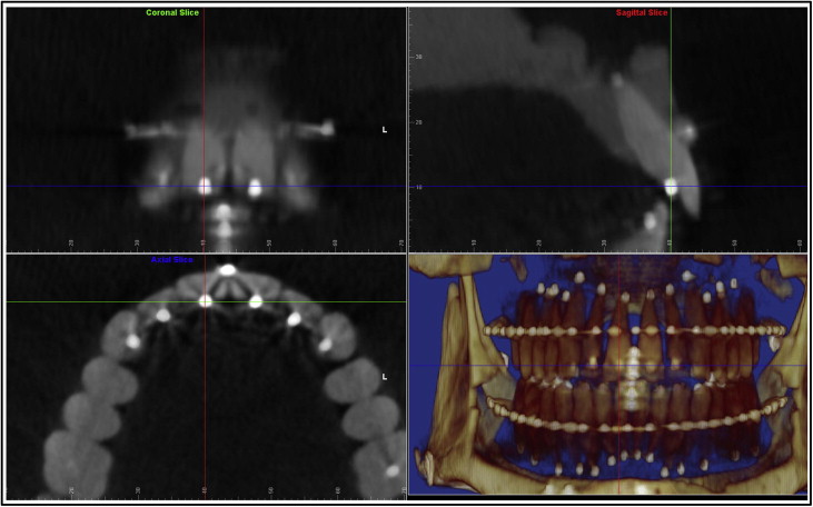
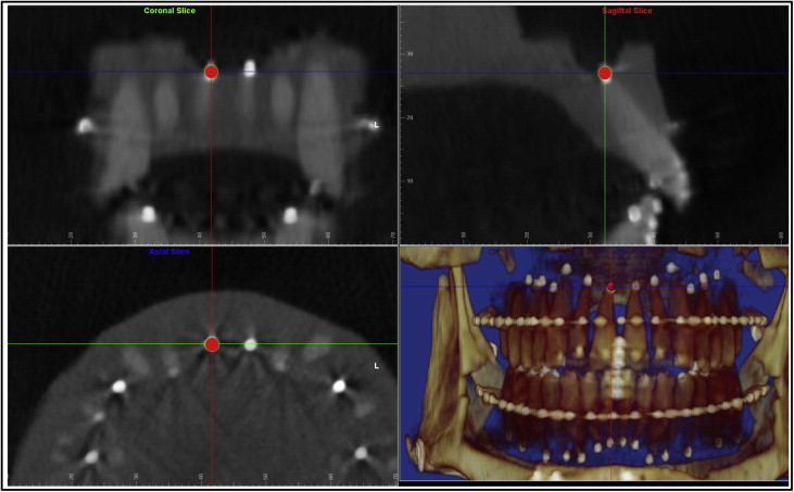
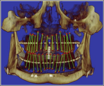
The digitization of each tooth’s long axis was done in all 3 plane views, each perpendicular to the other 2 views. Parallel movements of the sagittal, coronal, and axial planes were made so that each would pass through the center of the white stainless steel marker representing either the crown or the root point of each tooth ( Figs 2 and 3 ). A red dot was digitized at the intersection of the 3 perpendicular planes in 1 of the 3 plane views; it would also appear automatically in the other 2 views. The order of digitization was from the maxillary right second molar to the maxillary left second molar, and from the mandibular left second molar to the mandibular right second molar. Figure 4 shows all the white stainless steel markers replaced by the red digitization points. The green lines represented the long axes of the teeth after the digitization was completed in both arches.
Next we digitized the archwires. For the maxillary arch, the global coordinate saved for the maxillary teeth was restored first, and the maxillary archwire was digitized in the axial plane view set at the archwire level ( Fig 5 ). Four teeth on the right side were digitized along the archwire: midincisor, canine, second premolar, and second molar. The software program would add the mirror image of the right side half arch to the left side, constructing a symmetrical arch form. The mandibular archwire was digitized in the same way after the global coordinate saved for the mandibular arch was restored.
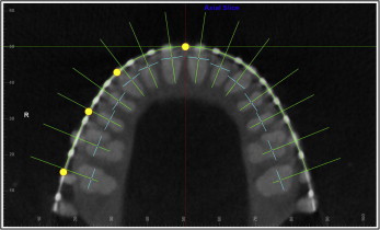
Then the tooth-specific coordinate system for the mesiodistal angulation and the faciolingual inclination measurements was set up. Once the arch form was digitized, the custom USC root vector analysis program would automatically construct another 3-plane coordinate system consisting of multiple coordinates, each specific for only 1 tooth for its mesiodistal angulation and faciolingual inclination measurements ( Fig 5 ): the transverse plane was the same axial plane at either the maxillary or the mandibular archwire level as in the global coordinate system; the straight green line represented the faciolingual plane that passed through each tooth crown point (dark blue dot) and was perpendicular to the archwire; the short light blue line represented the mesiodistal plane that also passed through each tooth crown point, but was perpendicular to the faciolingual plane. The mesiodistal angulation and the faciolingual inclination were measured for each tooth in its corresponding tooth-specific coordinate.
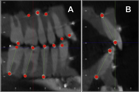
As shown in Figure 6 , A , the mesiodistal angulation was measured from the projection of the tooth’s long axis on the mesiodistal plane to the vertical line formed by the intersection of the mesiodistal and faciolingual planes. If the root center was distal to the crown center, the measurement would be positive; otherwise, it would be negative. The faciolingual inclination was measured from the projection of the tooth’s long axis on the faciolingual plane to the vertical line formed by the same intersection of the mesiodistal and faciolingual planes ( Fig 6 , B ). If the root center was lingual to the crown center, the measurement would be positive; otherwise, it would be negative.
At this point, the custom USC root vector analysis program would use algorithms to measure the mesiodistal angulation and the faciolingual inclination values for all teeth automatically.
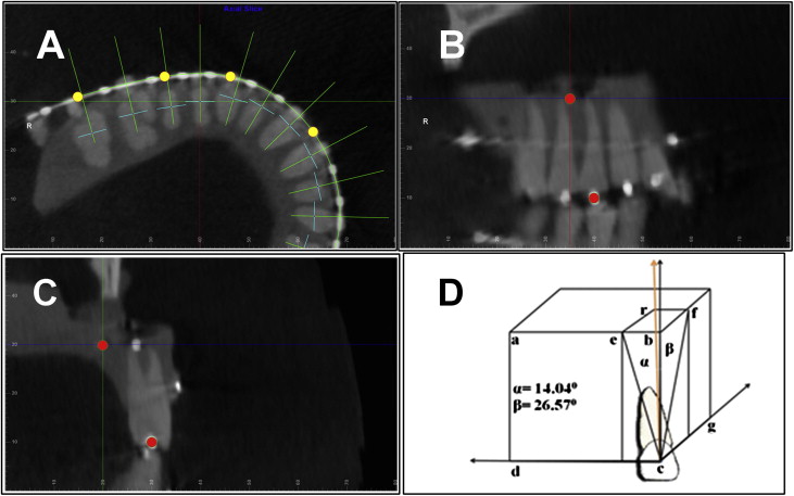
Teeth with known mesiodistal angulation and faciolingual inclination values were measured. The same 5 typodont images above were used again, except that the root points of the maxillary right first molar and first premolar, the maxillary left central incisor and second molar, the mandibular right second molar and canine, and the mandibular left lateral incisor and first molar were not digitized at the stainless steel balls representing the apices of these teeth but at locations defined through the following three steps ( Fig 7 ): (1) in the axial slice view ( Fig 7 , A ) at the crown point level, the image was rotated so that for the tooth to be digitized, the faciolingual direction was shown vertically and the mesiodistal direction was shown horizontally; (2) in the mesiodistal ( Fig 7 , B ) or faciolingual ( Fig 7 , C ) slice view, the transverse plane at the crown point level was moved 20 mm apically; and (3) in the mesiodistal slice view ( Fig 7 , B ), the faciolingual plane was moved 5 mm distally, and in the faciolingual slice view ( Fig 7 , C ), the mesiodistal plane was moved 10 mm lingually. After these parallel movements of the reference planes, the 3-plane intersection would be at a point that was 20 mm apical, 10 mm lingual, and 5 mm distal from the crown point. The root point was digitized at this intersection. Trigonometric calculation should give the tooth 14.04° of mesiodistal angulation and 26.57° of faciolingual inclination. For the maxillary right first molar and the mandibular left lateral incisor, the root points were placed mesially instead of distally to reflect their distal angulation; for the 2 mandibular molars, the root points were placed buccally instead of lingually to reflect their lingual crown inclinations.
Statistical analysis
To ensure that the measurement methodology described above was reliable, the principal investigator (H.T.) randomly chose 5 images from the 25 independent scans of the same typodont obtained from the University of Alberta. Digitizations were done a week apart, and intraclass correlation coefficients for the mesiodistal angulation and faciolingual inclination measurements were calculated.
One-sample t tests were used to check for statistically significant differences between our 5-time repeated mesiodistal angulation measurements and the coordinate measuring machine’s true mesiodistal angulation values for each tooth. The α level was adjusted to 0.05/28 = 0.001786 for the multiple t tests based on the Bonferroni adjustment. One-sample t tests were also used to compare the 5-time repeated mesiodistal angulation and faciolingual inclination measurements with the given mesiodistal angulation and faciolingual inclination values for each of the 8 selected teeth. The α level was adjusted to 0.05/8 = 0.00625.
Stay updated, free dental videos. Join our Telegram channel
VIDEdental - Online dental courses


