CHAPTER 9 Root Form Implant Surgery: Generic
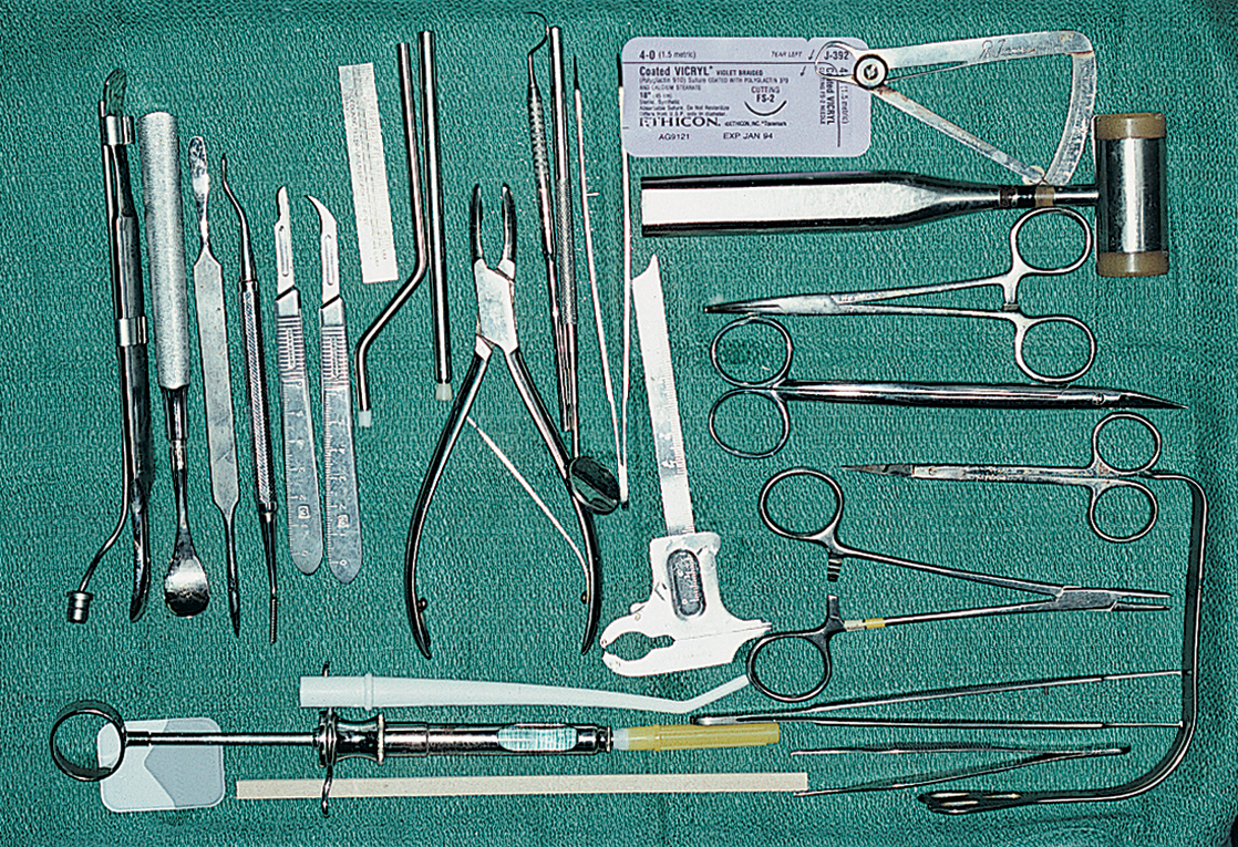
ARMAMENTARIUM
Before undertaking the placement of any type of root form implant, the practitioner should read this section in its entirety. It lists the introductory techniques of insertion for all types of root forms. In addition, recommendations are found in the tables of Chapter 4 for the selection of a wide variety of implant designs. The techniques for placement of the specific proprietary designs are presented in chapters 10 and 11.
After acquiring an understanding of each maneuver, the reader should refer to Chapter 4. Its charts describe most of today’s implant varieties, their general grouping, material and design characteristics, surface finishes, methods of primary retention (during the integration period), and basic restorative options. Several systems offer implants with diameters of 3, 3.25, and 3.3 mm (small diameter). Especially in the maxillae, such implants often may be inserted after a 3-mm diameter drill is used without the formality of tapping, enlarging, or countersinking.
CAVEATS
Perforations of the cortical plates must be avoided. Systems that supply backup (or larger) implant diameters are valuable in case an oversized osteotomy is made (see Chapter 28 for specifics).
Burs and drills should be marked with the number of times used and discarded when they become dull.
Bone drills should be pumped vertically, rather than in an arc, to introduce copious irrigant and to encourage straight osteotomies.
In the planning stages, a surgical template should be prepared for implant placement (see Chapter 4 and this chapter). However, the surgeon should keep in mind that sometimes, even the most careful planning does not yield satisfactory results because the bony ridge is not found directly below the soft tissues. The surgeon must be versatile enough to alter the positions and angles of the implants at the time of surgery.
Root form selection procedures (see Chapter 4) should be reviewed for the manufacturers’ recommended drilling speeds for different implant systems.
SURGICAL TEMPLATES
As surgeons gain more experience, they will find that the same template may be used for radiographic diagnosis (Chapter 4), for surgical placement, and even for uncovering the implants. Fabrication of the surgical template is a necessary step in the planning and placement of implants. Its design is based on the anatomic, prosthetic, and esthetic considerations. If (as discussed in Chapter 4) a diagnostic, 5-mm, ball-imbedded Omnivac template is available and each ball has been processed at a potential implant site, simply removing the balls allows the device to be used as an implant site locator. However, a template can be fabricated to be used specifically for intraoperative guidance.
Template for Single Tooth Replacement or Edentulous Spans Between Natural Teeth
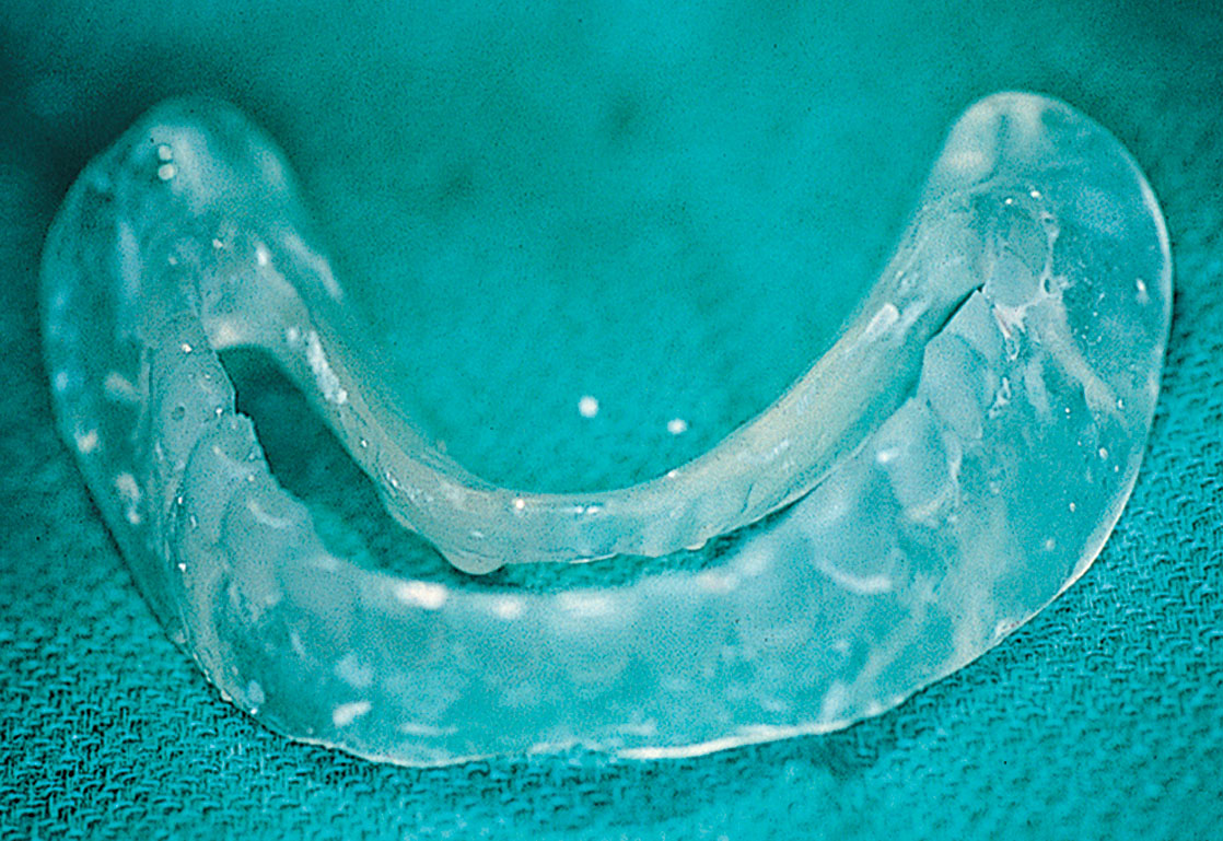
The process of single tooth replacement begins with marking a cast at the ideal location for the implant. A denture tooth then is fixed in place with sticky wax. Next, an Omnivac shell is created using 0.02-inch clear material. After the material has cooled, the plastic is trimmed to include at least two teeth on either side of the operative area. In the edentulous area, the parts of the appliance that extend buccally and lingually beyond the points of flap retraction (approximately 6 mm) should be shortened. The denture tooth is removed, and the occlusal and lingual surfaces of the denture teeth area are snipped away with a fine shears. The device should be cold sterilized and placed into position over the bone after flap retraction. It is stabilized by the teeth on either side of the host site, and it serves as an efficient surgical guide (Fig. 9-1).
Template for Completely Edentulous Sites
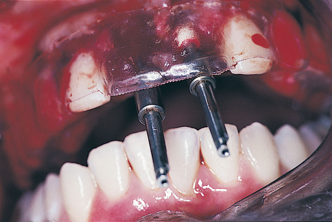
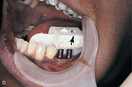
In the areas to be implanted, the lingual and occlusal aspects of the teeth are cut away with a bur in the form of a U-shaped trough; the incisal and facial surfaces are left intact. The fenestrated area denotes the sites where the implants are to be placed to satisfy the reconstructive and aesthetic needs of the case. Individual holes can be made, although this may prove too restrictive. The clear labial surfaces allow direct viewing during the preparation for osteotomies (Fig. 9-2). This not only ensures proper angulations, but also shows that the transepithelial abutments (TEAs) emerge from optimal areas, such as the cingula of incisors and the occlusal surfaces of molars.
SURGICAL TECHNIQUES
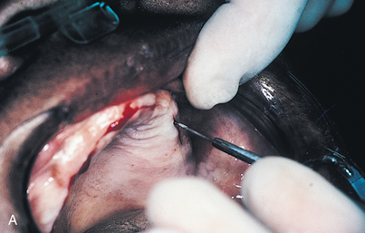
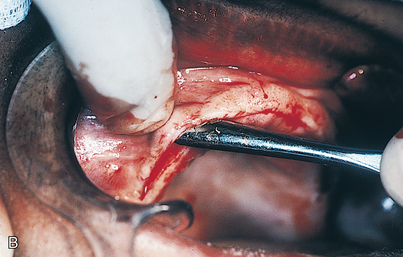
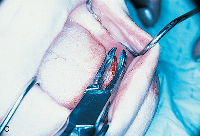
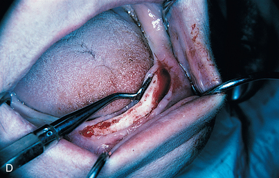
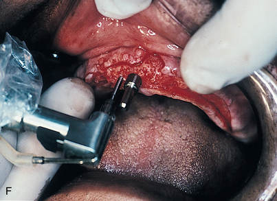
An infiltration technique is used to anesthetize the patient. A crestal incision then is made directly to bone, with adequate relief at either end, and the mucoperiosteum is reflected, exposing the bony operative site (Fig. 9-3, A and B). At this point, the bone is assessed. If the ridge is too narrow (i.e., knife edged), the surgeon must determine whether it can be flattened to an acceptable width and still have sufficient depth to accommodate an implant. If so, side-cutting rongeur forceps are used, and then a small, round vulcanite bur or a fissure type with irrigation (Fig. 9-3, C). Final smoothing is done with a bone file (Fig. 9-3, D). If the narrow ridge cannot be corrected but is deep enough, the surgeon should consider ridge augmentation (see Chapter 8) or placement of a blade implant (see Chapter 12).
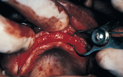
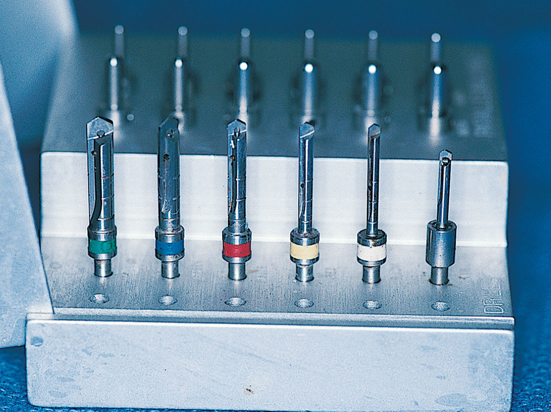
After the ridge has been prepared and measurements indicate that the width is adequate (i.e., at least 5.25 mm) (Fig. 9-3, E), the osteotomies are made. As an alternative, ridge-widening procedures may be undertaken (see Chapter 8). (The surgeon must keep in mind that implants must be spaced one full width apart.) A colored sleeve is placed on the shaft of each drill at the level of the planned depth of each osteotomy (yellow Disposaboots currently are used) (Fig. 9-4). The drill tip pierces the rounded end, and the sleeve is slid up the shaft to mark the proper length.
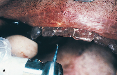
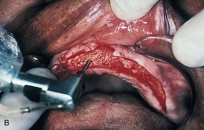
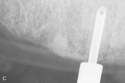
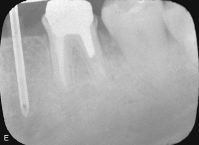
The sterilized, clear acrylic, Omnivac surgical template is placed in the patient’s mouth. The flanges are trimmed so that they will nestle comfortably beneath the reflected flaps of tissue; in this position, the flanges keep the flaps reflected. The template is stabilized with the host bone that appears directly beneath the U-shaped window. The starter bur (No. 2 round) is set in the center of each proposed implant site and rotated only into the cortex. Copious coolant is used, even though most starter burs are not equipped for internal irrigation. For each planned implant, a similar starter hole is made and then deepened just through the cortex (Fig. 9-5, A).
After the starter bur, the pilot drill is used. This drill, which is 1.6 mm in diamete/>
Stay updated, free dental videos. Join our Telegram channel

VIDEdental - Online dental courses


