CHAPTER 6 Preparations for Implant Surgery
ARMAMENTARIUM AND THE OPERATORY
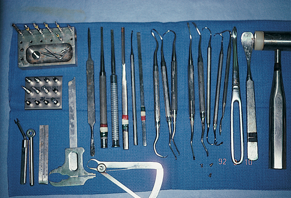
Most of the chapters in this book begin with warnings or caveats. This is an instructional chapter; therefore the only warning offered is that the readers, even if they do not plan to perform implant surgery itself, should acquire an understanding of the basic principles of surgery before attempting to plan or place implants. Although implant surgery is less demanding and less complex than many other kinds of oral surgery presented in this chapter, the operative path can be filled with complications. A knowledge of management is required, therefore, before the practitioner can begin the practical endeavors in implantology. For those who do intend to perform the surgery, a gentle reminder is offered to check and replenish instruments and disposable supplies before any procedure is started. Although some of the items listed in the armamentarium may seem arcane or may appear unlikely to be required, their presence prepares the surgeon for virtually any unexpected occurrence (Fig. 6-1). Also, this chapter should be read slowly, at a time of leisure, so that the practitioner can learn its contents completely. Readers must have a clear knowledge of their skill level, so that they do not find themselves in a situation in which significant corrective procedures may be required.
Operatory
The bulk of implant surgery procedures are performed in the office operatory. The practitioner should try to assemble the equipment required for all planned procedures in this area or room, because this provides maximum convenience for the surgeon and staff and the greatest comfort for the patient. A commodious, complete operatory helps make the treatment of patients more enjoyable. Some basic concepts can be followed in the design of an implant operatory (Fig. 6-2).
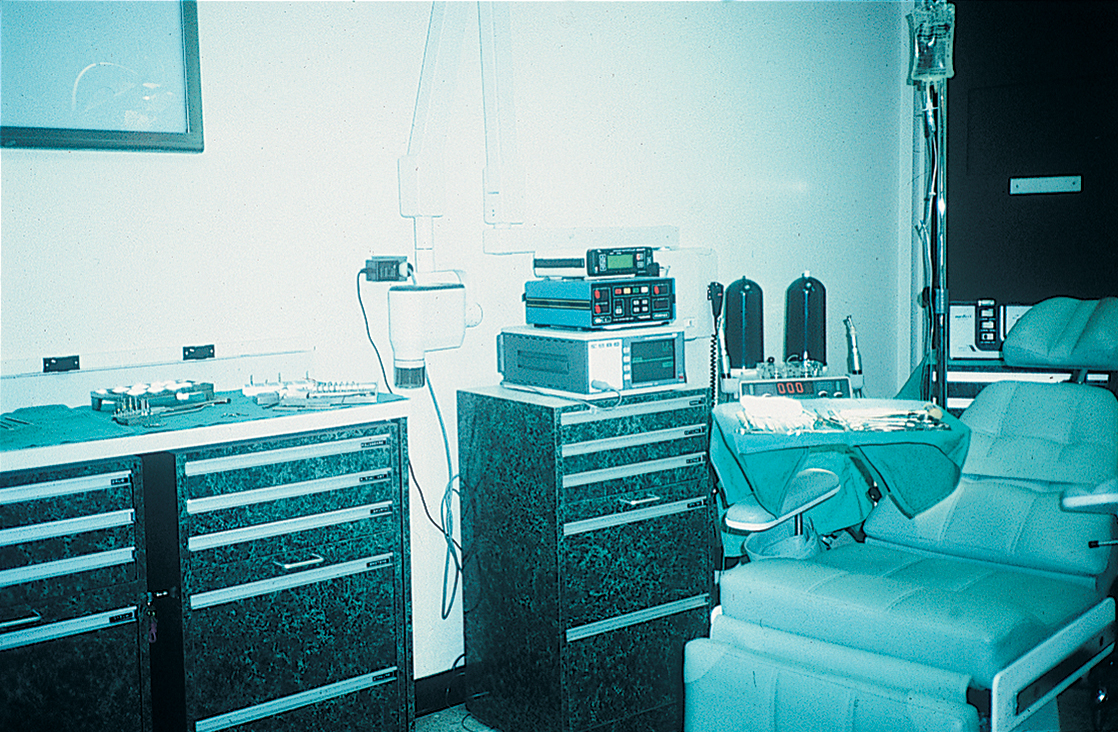
A bracket table or Mayo stand large enough for all needed instruments must be a part of the facility. Adequate countertop and shelving areas are essential to accommodate the requisite implant equipment (e.g., console, motors, handpieces, irrigation bottles) and devices for monitoring vital signs (e.g., GE Dinamap, Criticare, noninvasive blood pressure, pulse rate, three-lead electrocardiograph, pulse oximeter). Standby instruments for implant surgery must be located conveniently and within clear visual range, and an emergency tray or crash cart should be available.
Electrical Delivery Systems
An electrical surgical system has four basic components: a console, a motor, a handpiece, and burs or drill bits (or piezosurgical insert tips). In-depth examination of each component and its relationship to the others can help the practitioner understand the entire system. It is important not only to understand the intricacies of both electrical and air- or nitrogen-powered units, but also to comprehend the surgical demands made by the various implant systems. Some require higher speeds and less torque, whereas others require lower speeds and greater torque.
Console
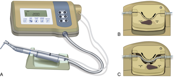
The console contains all of the electrical circuitry; the controls for speed, torque, irrigation pumps, and handpiece selection; the power source; and a light-emitting diode (LED) readout for revolutions per minute (rpm). Even the foot-controlled rheostat plugs into the unit and is powered by the console (Fig. 6-3).
Electric Motors
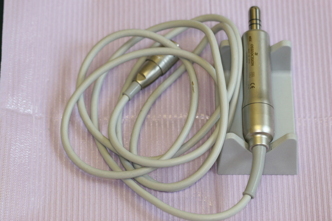
The motor housing cord plugs into the front of the console and uses its voltage supply, much the same way a cassette or CD player uses a stereo amplifier (Fig. 6-4). The tiny motors inside the housing are commonly referred to as micromotors, and they are designed to run at different speeds.
Most practitioners who purchase an electrical delivery system buy the console and motor together, because one manufacturer’s motor may not couple with the console of another manufacturer. To ensure greater accuracy in readings, one brand should be chosen for all components.
Troubleshooting
If any of the following are noted while the motor is in use, action must be taken:
Table 6-1 20,000 rpm Electric and 90 psi 20 k Air or Nitrogen Motors
| Contra-Angle Reduction | Approximate Speed Range (rpm) | Approximate Power Range (rpm) |
|---|---|---|
| 10:1 | 200-2000 | 1700-2000 |
| 16:1 | 78-1250 | 950-1250 |
| 17:1 | 70-1175 | 875-1175 |
| 18:1 | 60-1110 | 850-1100 |
| 20:1 | 50-1000 | 800-1000 |
| 64:1 | 25*-312 | 50-312 |
| 70:1 | 20*-285 | 50-285 |
| 100:1 | 18*-200 | 40-200 |
| 120:1 | 15*-166 | 25-166 |
| 256:1 | 10*-78 | 15-78 |
| 280:1 | 8*-70 | 15-78 |
* Minimum speed at which the bur will cut without stalling.
Table 6-2 30,000 rpm Electric and 90 psi 20 k Air or Nitrogen Motors
| Contra-Angle Reduction | Approximate Speed Range (rpm) | Approximate Power Range (rpm) |
|---|---|---|
| 10:1 | 300-3000 | 2500-3000 |
| 16:1 | 115-1875 | 1200-1875 |
| 17:1 | 100-1765 | 1150-1765 |
| 18:1 | 90-1660 | 1100-1660 |
| 20:1 | 75-1500 | 850-1500 |
| 64:1 | 50*-468 | 60-468 |
| 70:1 | 40*-428 | 50-428 |
| 100:1 | 25*-300 | 40-300 |
| 120:1 | 20*-250 | 25-250 |
| 256:1 | 10*-119 | 20-119 |
| 280:1 | 10*-107 | 15-107 |
* Minimum speed at which the bur will cut without stalling.
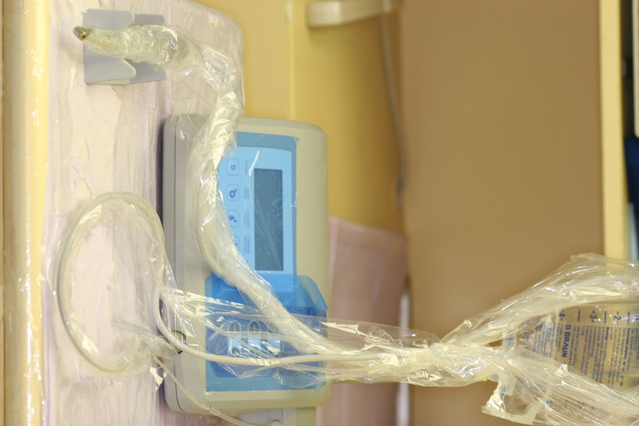
The sterility of electric motors is an issue involving cost and versatility. Most autoclavable motors cost three times as much as motors that cannot be autoclaved. Autoclavable motors usually are rated at no more than 20,000 rpm, and they run hotter than motors that cannot be autoclaved because they have no cooling vents. However, motors that cannot be autoclaved can be used with sterile, transparent drapes (e.g., Steri-Drapes, which are supplied with adhesive). These wraps are inexpensive and disposable and fit any standard electric motor (Fig. 6-5). They cover the connections at the console and allow the controls to be used through them.
Handpieces
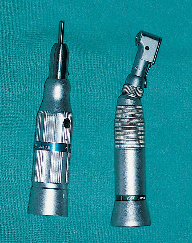
The term handpiece is one of the most misused words in dentistry. Simply defined, a handpiece is any apparatus attached to an electrical or an air- or nitrogen-powered motor that accepts a bur. There are two types of handpieces: contra-angle and straight (Fig. 6-6); these enable the practitioner to increase or maintain a motor’s speed reliably.
Handpieces that reduce a motor’s top speed are referred to as speed-reduction handpieces. These are rated by the ratio of speed decrease they can achieve (e.g., a 16:1 reduction handpiece reduces a motor’s top speed by 16 times). As speed is decreased, torque is increased by the same ratio. Conversely, reduction handpieces have more power at higher speeds than at lower speeds. This phenomenon is called the handpiece power zone. With a 16:1 reduction on a 20,000-rpm motor, power is greater at 1250 rpm than at 500 rpm. Table 6-1 shows that a 16:1 reduction handpiece has near-maximum power between 950 and 1250 rpm. Below 950 rpm, both speed and power are lost rapidly. If the same 16:1 reduction handpiece is used on a 30,000-rpm motor, the top speed increases to 1875 rpm, and the power zone is found at the 1200-rpm level. It is critical that the surgeon know the motor’s top-rated speed and the handpiece power zone.
Power Ranges of Handpieces
Every handpiece has more power at higher speeds than at lower speeds. It is important for the practitioner to know the speed at which the torque of each system is highest. Most of the problems that occur during root form surgery happen because changes in drill diameter are not made in sufficiently small increments and because dull drills are not changed often enough. If the practitioner observes the following six simple rules, as well as the power ranges in Tables 6-1 and 6-2, the chances for problem-free surgery are greatly enhanced:
Table 6-3 presents a list of currently available systems and some of their specifications.
| Different Console Jacks for Different Speeds | Different Motors for Different Speeds | Different Contra-Angles for Different Speeds | Tapping Capability | Reverse Capability | Audible Alarm | Autoclavable Motor | Internal Irrigation | Single Unit (1 Motor) | Double Unit (2 Motors) | Electric | Gas or Air | Variable Speed | Foot Control | Variable Irrigation Pump Flow | Output Display (rpm) | ||
|---|---|---|---|---|---|---|---|---|---|---|---|---|---|---|---|---|---|
Motor & piezo
Stay updated, free dental videos. Join our Telegram channel
VIDEdental - Online dental courses


