9
Radiographic Interpretation of Traumatic Injuries
Introduction
The world of endodontics has witnessed several changes in the past decade. New technologies, instruments, and materials have resulted in better diagnosis and more predictable therapy. The application of computer based-systems and the development of electronic sensors have provided the technical means to apply theoretical principles to diagnostic imaging. Among these innovations, digital radiographic imaging has introduced a new dimension with many potential benefits for endodontic practice and has significantly improved the ability to accurately diagnose in a cost- and dose-efficient manner (Berkhout et al., 2004). Recent improvements in three-dimensional (3D) digital radiographic imaging introduced a new perspective, allowing us to evaluate the anatomic structures, both hard and soft tissue, in three spatial planes (Scarfe, 2005). Comparing with the traditional projection (plain film) radiograph, which is a two-dimensional shadow of a 3D object, 3D imaging overcomes this major limitation by providing a true representation of the anatomy while eliminating superimpositions. Several studies have reported the use of computerized tomography and digital radiography for differential diagnosis (Shrout et al., 1993; Simon et al., 2006; Trope et al., 1989), assessment of treatment outcomes (Camps et al., 2004; Cotti et al., 1999), endodontics (Cotton et al., 2007), oral and maxillofacial surgery (Danforth et al., 2003a; Eggers et al., 2005; Ziegler et al., 2002), implantology (Hatcher et al., 2003; Sato et al., 2004), and orthodontics with reliable linear measurements for reconstruction and imaging of dental and maxillofacial structures (Baumrind et al., 2003; Danforth et al., 2003b; Maki et al., 2003).
The incidence of dental trauma due to falls, sports, automobile accidents, and violence has increased significantly in recent decades, affecting children’s and teenagers’ anterior teeth (Andreasen and Andreasen, 1994). In combination with clinical tests and observations such as percussion, palpation, tooth mobility, coronal color changes, pulp sensitivity, and vitality, the first clinical and radiographic examination of the traumatized patient is critical. The information gathered allows the clinician to determine the initial diagnosis, severity of the injury, develop a treatment plan, and create a baseline for follow-up. When correctly performed and adequately interpreted, these tests are reliable in diagnosing pulp necrosis (Andreasen, 1988a).
Following a traumatic injury, we must differentiate between the first radiographic examination of the patient, immediately after the injury, and the follow-up examinations. During the first radiographic examination, our focus should be on diagnosing bone fractures of the mandibular and maxillary processes, alveolar bone fracture(s), root fracture(s), displacement of teeth, and stage of root development/maturation. Follow-up radiographic examination is aimed at diagnosing widening of the periodontal ligament (PDL), disturbance of lamina dura, periapical radiolucencies, root resorptions, repair of root fractures, pulp canal obliteration, and root maturation/development.
Stage of Root Development
In 1960, Nolla published classification for odontogenic development using radiographic interpretation (Table 9.1) (Nolla, 1960). This classification has been widely used by all specialties throughout the years including current articles (Oliveira et al., 2008; Pioto et al., 2005).
Table 9.1 Radiographic classification for odontogenic development.
| 0 | No crypt |
| 1 | Presence of crypt |
| 2 | Initial calcification |
| 3 | One-third crown completed |
| 4 | Two-thirds crown completed |
| 5 | Crown almost completed |
| 6 | Crown completed |
| 7 | One-third root completed |
| 8 | Two-thirds root completed |
| 9 | Root almost open (open apex) |
| 10 | Root apex completed |
Knowledge of the developmental stages of permanent teeth is essential for clinical practice in several dental specialties, since it may influence diagnosis, treatment planning, and outcomes. This is particularly true in cases of immature and traumatized teeth. In 1976, Fulling and Andreasen demonstrated that the late differentiation of Ad nerve fibers in the dental pulp could explain the lack of a reliable and predictable response of erupting and undeveloped teeth to thermal and electrical stimulation (Fulling and Andreasen, 1976). In young patients with immature teeth, carbon dioxide (CO2) snow and dichlorodifluoromethane are the most reliable sensitivity tests followed by the electric pulp test and ethyl chloride and ice (Fuss et al., 1986). Therefore, in absence of reliable clinical tests, radiographic evidence of root development and dentin maturation during follow-up examination may be critical in providing the clinician with reliable information related to the presence of a vital dental pulp.
Traumatic Injuries
Radiographic interpretations of traumatic injuries will be thoroughly described and illustrated using the classification proposed by Andreasen and Andreasen in 1994 (Glendor et al., 2007) and adopted by the World Health Organization (WHO). Feliciano and Franca Caldas evaluated 164 articles and 54 different classifications and they concluded that, according to the literature, the most frequently used classification system was that of Andreasen (32%) (Feliciano and de Franca Caldas, 2006). Treatment recommendations are based on the official guidelines of the International Association of Dental Traumatology (IADT) (Flores et al., 2007a, 2007b, 2007c).
Injuries to the Hard Dental Tissues and the Pulp
Figure 9.1 Clinical and radiographic diagnosis of enamel fracture of the maxillary left central incisor.
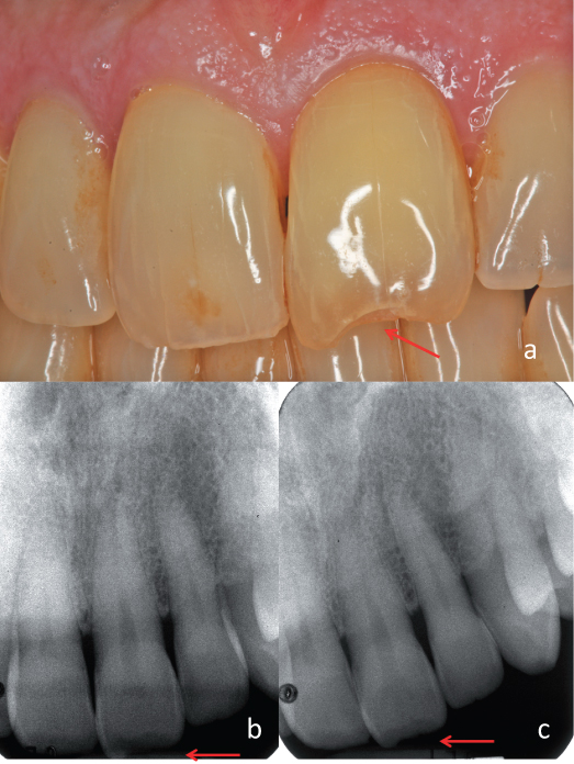
Figure 9.2 Lip laceration and swelling. A radiograph of the lip demonstrated the presence of tooth fragments within soft tissues.
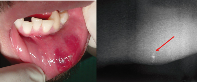
Figure 9.3 Uncomplicated crown fracture of the maxillary right central incisor. (a) Preoperative and (b) postoperative restoration with composite resins.
Courtesy of Dr. Gabriela Ibarra.
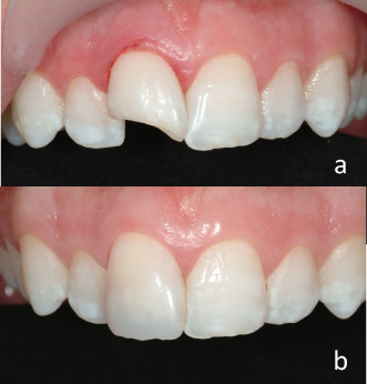
Figure 9.4 Complicated crown fracture of the maxillary left central incisor. (a) Preoperative and (b) postoperative restoration with composite resins.
Courtesy of Dr. Gabriela Ibarra.
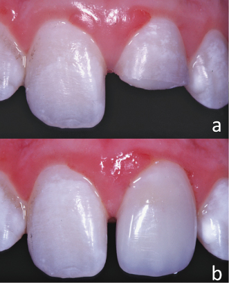
Figure 9.5 Complicated crown fracture of the maxillary right central and lateral incisors and maxillary left central incisor. (a–b) Periapical radiographs at different horizontal angles.
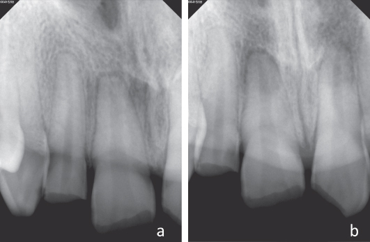
Figure 9.6 Complicated crown fracture of the maxillary right central and lateral incisors and maxillary left central incisor (same case of Figure 9.5). Cone beam computed tomography demonstrating an additional crown–root fracture on the maxillary right lateral incisors that was not visible on the periapical radiographs.
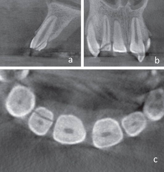
Figure 9.7 Complicated crown fracture of the maxillary right central incisor. Partial pulpotomy procedure clinically illustrated by steps: (a) Pulp exposure, (b) pulpal tissue excised 2 mm below the exposure, (c) bleeding control by pressure only (cotton pellet moisted on saline), (d) hemostasis obtained, (e) white MTA seal, and (f) protection of the MTA using a layer of glass ionomer lining.
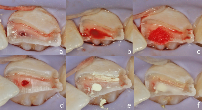
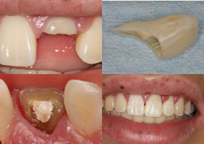
Figure 9.8 Crown–root fracture of the maxillary left central incisor. (a) Clinical view of the fracture immediately after injury, (b) periapical radiograph demonstrating the complicated crown–root fracture, (c) clinical gingivectomy exposing all the fracture’s fragments, and (d) remaining tooth structure after removal of the fracture fragments.
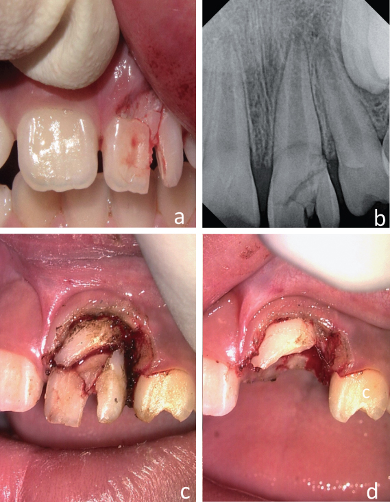
Figure 9.9 Crown–root fracture of the maxillary left central incisor. (a–c) Periapical radiographs at different horizontal angles.
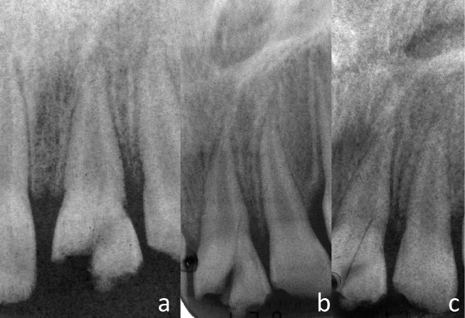
Figure 9.10 Crown–root fracture of the maxillary left central incisor (same case of Figure 9.9). Periapical radiographs. (a) Immediately postoperative, (b) 2 months follow-up, and (c) 6 months follow-up.
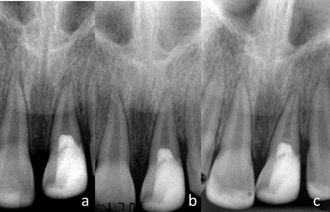
Figure 9.11 Crown–root fracture of the maxillary left central incisor. (a–d) Emergency procedure for stabilization of the coronal fragment with acid etch/resin splint to the remaining tooth structure and adjacent teeth.
Stay updated, free dental videos. Join our Telegram channel
VIDEdental - Online dental courses


