Chapter 9
Dental Implant Placement Including the Use of Short Implants
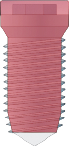
Branemark’s exploration of the vascular supply to healing bone evolved into the concept referred to as osseointegration. The physical design of his prototype dental implant was made of titanium that was milled into a cylindrical screw form with a tapered apical end and a coronal flared neck topped by a circular platform. A hex nut was milled into the corona and a screw chamber was bored and tapped through this into the body of the implant for fixation of external devices (Fig. 9.1).
Fig. 9.1. Image of a Branemark implant depicting design and surface structure. (Reprinted with permission from Branemark PI, et al. 1985. Tissue-Integrated Prostheses. Quintessence, Chicago.)
A full-thickness flap was reflected and the bone crest exposed. The implant was placed by preparing a cylindrical hole through the compact bone of the crest and extending it to engage cortex at the base of the mandible, floor of the nose, or the floor of the sinus.
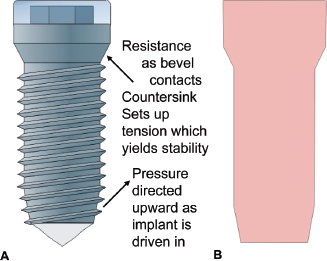
The osteotomy represented the body of the implant without threads (Figs. 9.2 and 9.3) Threads were tapped into the sides of the osteotomy when necessary, and the entry was countersunk to match the screw threads and the flared neck of the implant. A cover screw was placed over the external hex platform to seal the attachment chamber. The entire preparation was done with careful attention to measurement so that the finished installation lay flush with the bone surface. The entry flap was then sutured passively with the partial dissection marginal incision providing primary connective tissue approximation and rapid healing.
Fig. 9.2.A, Osteotomy outline followed by implant placement (cylindrical shape).B, Outline of implant that will fit the osteotomy site.
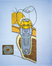
Fig. 9.3. Implant fitted into the osteotomy site (cylindrical shape).
Branemark’s surgical technique required adherence to certain principles based on his teams studies:
1. Atraumatic bone preparation with attention to minimizing heat production: constant irrigation
2. Primary surgical stability achieved with bicortical stabilization where possible (upper anterior/lower anterior)
3. Spacing of multiple implants: 7.0 to 7.5 mm on center
4. Provide healing interval with no direct load to allow undisturbed osseointegration
Most of these early implants were placed in the mandibule between the mental foramina and maxillary anterior/bicuspid regions. The objective was to offer an alternative to an inadequate removable prosthesis.
Implants have become a standard of care and the treatment of choice for replacement of missing teeth. All areas of the mouth have been restored, and while the threaded implant is still the dominant form, the cylindrical shape and the attachment platform have evolved.
Three basic forms that are available are the cylinder with screw threads (Branemark’s design), the tapered cylinder with threads (e.g., Zimmer [Figs. 9.4 and 9.5]), and the tapered form without threads, which is press fit (Bicon [Fig. 9.6] and Endopore). The internal architecture of the bone influences the effectiveness of these forms to gain the necessary stability at time of placement.
Fig. 9.4. Tapered implant and outline of osteotomy site.
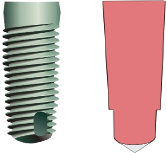
Fig. 9.5. Tapered implant within the osteotomy site.

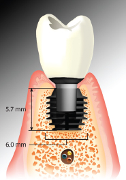
Fig. 9.6. Bicon short implant (5.7 [H11003] 6 mm) placed in the mandible (especially useful in cases with insufficient bony height).
Branemark stressed bicortical stabilization as a method to secure his implant system. His mechanical shape creates stability by the resistance of the countersink to the draw or pull of the threads into the bony preparation (Fig. 9.2A); this requires heavy compact bone at each end of the osteotomy. To ensure maximum use of bone and bicortical engagement (CT was not available then), the suggestion was made to place the finger firmly against the base of the mandible and to feel that the bur had penetrated the cortex. In the maxillary anterior, one was to place the finger in the nasal areas to feel the penetration of the floor of the nose (cortex). If the internal architecture had trabeculae of sufficient bulk, then the engagement of the more compact border areas was not needed. However, if the trabeculae were thin and widely spaced, such as in the upper and lower posterior, then the screw pressures could break or strip the bone threads in the body and apex area of the implant or collapse the coronal bevel and result in a “spinner.” It is possible to engage the cortex at the floor of the sinus and the top of the mandibular canal, but this is often not desirable.
As the scope of placement widened to include the posterior areas and single tooth sites, the need for alternate mechanics of surgical stability evolved.
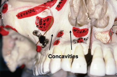
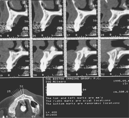
Originally designed to fit tapered cross sectional sites (areas with depressions like the incisal fossa and the depression over the upper first bicuspid) the tapered form is especially useful in areas of light, thin trabeculation (Fig. 9.7)
Fig. 9.7. Dry scull and CT scan showing specific anatomic features and trabeculation of the maxillary bone.
The tapered screw form provides an alternative method of achieving surgical stability. Its wedge-shaped screw form achieves compression of the tapered osteotomy along its entire surface (see Figs. 9.4 and 9.5).
Dental implants are used to:
1. Replace individual teeth
2. Support fixed and removable prostheses
3. Anchor maxillofacial prosthesis
4. Act as anchorage for orthodontic movement
Anesthesia
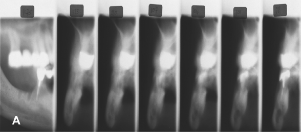
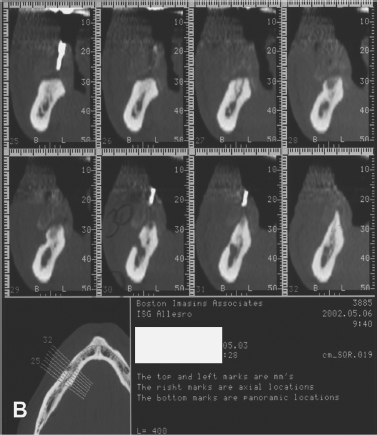
Block anesthesia is the most efficient. Marcaine supplemented with lidocaine provides 3 to 4 hours of good working anesthesia with minimal local reinforcement. Some practitioners prefer only infiltration so that the patient “feels” the proximity to vital structures and thus avoid potential damage to nerves. With a distortion level of 1% or less, the reformatted CT images, coupled with a surgeon’s “feel” for anatomy, can be used with confidence (Figs. 9.8 and 9.9).
Fig. 9.8.A, Panoramic radiograph (distortion ±25%).B, Periapical radiograph (distortion ±15%).
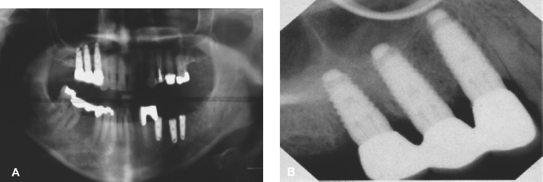
Fig. 9.9.A, Tomograph: “foggy” quality and slice thickness distort image.B, CT scan: distortion ±1%.
Entry Incision
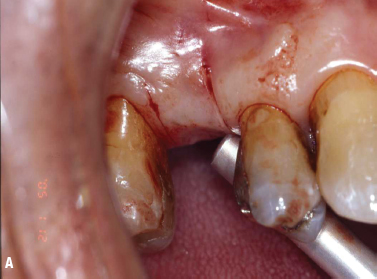
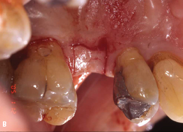
The objective is to expose the bone where the osteotomy is to be placed and to minimize vascular disruption to sensitive bone areas (Fig. 9.10).
Fig. 9.10. Incision design buccally (A) and palatally (B) before the placement of implant No. 4.
Incisions vary with site objective and history of local trauma.
1. If one-stage implant or immediate load, a mid crestal incision with intrasulcular extensions buccally and lingually is used.
2. If classic delayed, two-stage implant, then
- In the maxillary arch, a horizontal incision is usually made just to the palatal of line angles and two vertical incisions sparing the proximal papillae are extended through the mucogingival junction (MGJ) on the buccal. The flap is reflected into the vestibule and no retraction is needed (Fig. 9.11).
Stay updated, free dental videos. Join our Telegram channel

VIDEdental - Online dental courses


