8
Protocols for the Use of Cone Beam Computed Tomography in Orthodontic Practice
Introduction
Since its introduction to orthodontics in 2001, cone beam computed tomography (CBCT) has become a popular and useful tool in the diagnosis and treatment planning of orthodontic cases (Hans et al., 2011). Despite its popularity, a consensus regarding proper protocols for its optimal use has yet to be established. The objective of this chapter is to provide the clinician with practical information on how best to utilize CBCT imaging in the diagnosis and treatment of orthodontic patients. The overall goal is to provide the clinician with a greater understanding of the benefits of CBCT in specific clinical situations as well as how to manipulate and interpret the contents of the scan for optimizing orthodontic treatment. This will establish a foundation that the clinician can build upon during the ongoing dynamic phase in which CBCT imaging continues to evolve as a diagnostic tool.
Benefits of CBCT for Orthodontists
There remains some debate on which types of orthodontic cases warrant a CBCT scan versus the use of traditional two-dimensional (2D) projectional (plain film) radiographs (Halazonetis, 2012; Larson, 2012). In general, each case should be evaluated by the orthodontist to determine if the CBCT scan would provide valuable additional diagnostic information that could enhance or alter the treatment plan. The details of specific selection criteria for the use of CBCT in orthodontics are presented in Chapters 1 and 6.
The three-dimensional (3D) data derived from a CBCT scan can, in specific situations, reduce ambiguity in diagnosis, thereby improving the treatment plan and minimizing the risk of negative sequelae or elongated treatment times. Treatment plans based on incomplete or inadequate diagnostic data can result in permanent damage to teeth including an increased risk for decalcification, caries, and root resorption (Motokawa et al., 2011). Each case, therefore, should be evaluated to determine if the additional information available in a CBCT scan will decrease the risks inherent in that specific case. It is important to remember that the treatment and outcome of a case ultimately is only as good as its diagnosis.
In general terms, the benefits of acquiring, but not necessarily the rationale for taking CBCT scans are:
- Reduced ambiguity in diagnosis
- Minimization of unexpected issues and negative sequelae
- Acquisition of more diagnostic information, and/or
- Increased treatment efficiency.
Reduced Ambiguity
Ambiguity is defined as something that can be understood in two or more possible ways. When developing a problem list for an orthodontic case, the ability to interpret an anatomical feature in more than one way may result in several different treatment plans. Since traditional 2D projectional radiographs are prone inherently to issues such as magnification, artifacts, and superimposition of structures, the risk of having multiple possible interpretations of the anatomical structures increases (Botticelli et al., 2011).
The astute clinician will recognize the presence of ambiguity in a diagnostic image and will consider each possible treatment plan and outcome for each possible interpretation of the ambiguous area of the image. After considering how each interpretation might affect the patient’s treatment, the clinician may find that the treatment plan and outcome remains the same regardless of the interpretation. In these situations, the previously acquired imaging is adequate despite the ambiguity. If the clinician determines that different interpretations will result in differing treatment approaches and varying outcomes, however, the acquisition of further imaging then is warranted. The danger occurs when the clinician fails to recognize the areas of ambiguity in the diagnostic imaging and fails to assess their potential ramifications adequately.
Figure 8.1A shows a panoramic radiograph of an Angle Class III patient who displays multiple metallic-like opacities and numerous shadowing artifacts contributing to ambiguity in several areas. It was determined that a CBCT scan was necessary to minimize the ambiguity since several of the small opacities appear in close proximity to the apices of the mandibular teeth that would be undergoing orthodontic movement. Furthermore, a definitive diagnosis of the large opacity inferior to the patient’s left ramus could help in determining whether or not orthognathic surgery was a viable option to correct the Class III relationship.
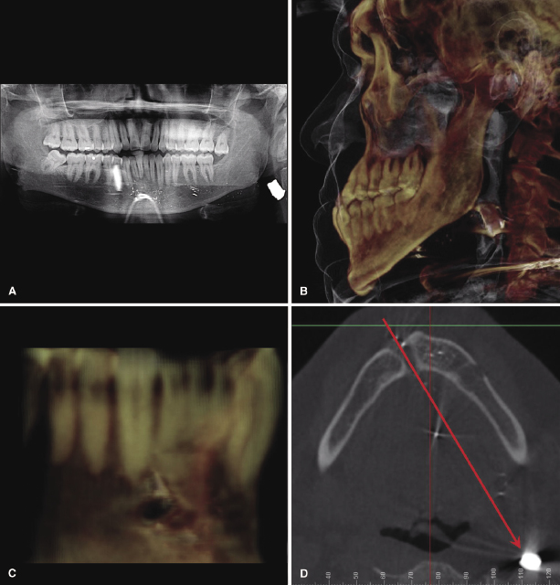
After a CBCT scan was taken, a bullet was localized inferior and posterior of the patient’s left ramus (Figure 8.1B) that the patient had failed to disclose on his health history. In addition, shrapnel from the bullet was found throughout the anterior mandible, but none was found blocking the likely paths of roots during orthodontic movements. The CBCT scan also clearly showed the entry point inferior to the mandibular right canine (Figure 8.1C). Using the entry point as a reference point, the bullet’s path could be extrapolated to its current resting place (Figure 8.1D). In this case, failure to eliminate the initial ambiguity properly could have resulted in damage to the apices of teeth by being moved into shrapnel or prescribing surgery when it was contraindicated.
Several studies have shown that the introduction of a CBCT scan into the diagnostic imagery of a specific case has resulted in a change in that case’s treatment plan (Bjerklin & Ericson, 2006; Botticelli et al., 2011). However, the same studies have shown that some treatment plans remain unchanged despite the inclusion of a CBCT scan. Instead of evaluating the value of CBCT scans in such black or white terms, other studies have emphasized the effect CBCT scans have on a clinician’s confidence in the treatment plan (Haney et al., 2010). In essence, findings of increased clinician confidence in treatment planning with CBCT imaging imply a decrease in the ambiguity of recognizing important diagnostic features.
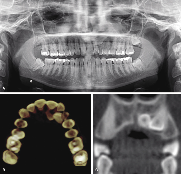
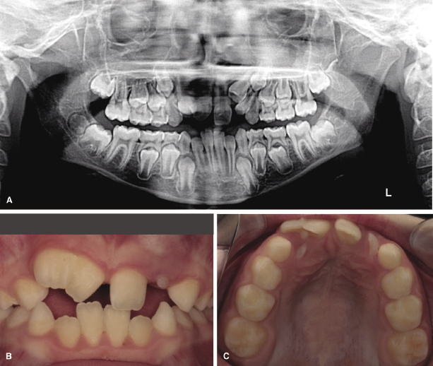
Figure 8.2A shows a panoramic radiograph of a 21-year-old female whose maxillary left canine has failed to erupt. It was unclear from 2D imaging why the canine had become ectopic and eventually impacted. However, a CBCT scan revealed that the canine was located in close proximity to a supernumerary tooth that had prevented its eruption (Figure 8.2B,C). The additional information not only answered the question of why the canine had failed to erupt, but also increased the clinician’s confidence that once the supernumerary tooth was removed, the canine could be brought into its proper position under orthodontic traction. In this case, the incorporation of CBCT imaging as part of the diagnostic records diminished ambiguity, helped refine the treatment plan, and potentially enhanced treatment outcome.
While CBCT imaging is indicated and useful in specific cases such as those described above (see also Chapters 1 and 6), it must be emphasized that if all areas of potential ambiguity can be discerned with a high degree of confidence using 2D projectional radiographs alone, taking a CBCT to reduce ambiguity further would be unjustified. Moreover, the decision to take 2D projectional radiographs as screening tools before determining if a CBCT scan is necessary presently is due to the higher radiation dose associated with CBCT scans versus 2D imaging (see Chapter 3). It is possible that in the future, as the dose associated with CBCT scans decreases to levels equal to or less than 2D imaging, this 3D imaging modality could gain greater acceptance for use as a diagnostic tool during initial orthodontic examination.
Minimization of Unexpected Issues and Negative Sequelae
The goal of a problem list is to identify all the current problems of a case. By focusing on the present, however, there may be a tendency to overlook potential future problems or negative sequelae of the treatment plan and its mechanics. One of the most common negative sequelae of orthodontic treatment is root resorption (Motokawa et al., 2011). This is found most commonly on maxillary lateral incisors when a canine has become impacted in close proximity to the incisor root. In addition to resorption on the lateral incisor roots, research conducted using CBCT imaging also has identified resorption on the roots of the central incisors and the first premolars (Walker et al., 2005). This problem can be made worse if care is not taken in determining the proper vector by which to retrieve the impacted canine (Becker et al., 2010a; see also Chapter 16). Thus, if forces are exerted in the wrong direction during canine retrieval, iatrogenic root resorption may result.
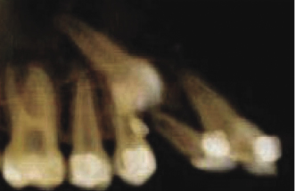
An unfortunate example of this point is illustrated in Figure 8.3. It shows an impacted maxillary right canine that has been under orthodontic traction for 19 months. The patient was referred by the orthodontist to an oral surgeon to determine why the tooth had failed to erupt despite being under constant orthodontic traction. The oral surgeon took a CBCT scan to localize the canine and discovered that the canine was not impacted palatally as the orthodontist had assumed, but instead was placed buccally. The utilization of an inappropriate palatal traction vector, possibly due to inadequate diagnostic information, resulted in the proclination of the adjacent lateral incisor, an unnecessary elongation of treatment time and likely iatrogenic root resorption.
A close examination of 2D projectional radiographs may reveal a series of recognizable problems. Due to the inherent inadequacies of these radiographs as noted elsewhere (see Chapters 1 and 11), these findings, when identified, may be a reflection of or result from additional significant underlying problems. For example, as with the case described previously where a supernumerary tooth was found contributing to a canine impaction (Figure 8.2), after an ectopic or impacted tooth has been identified, the clinician should focus not solely on determining the solution to the problem, but also on what may have caused the issue to occur in the first place. When the clinician discovers the likely cause of a significant clinical or radiographic finding, the ability to determine the best treatment plan often improves.
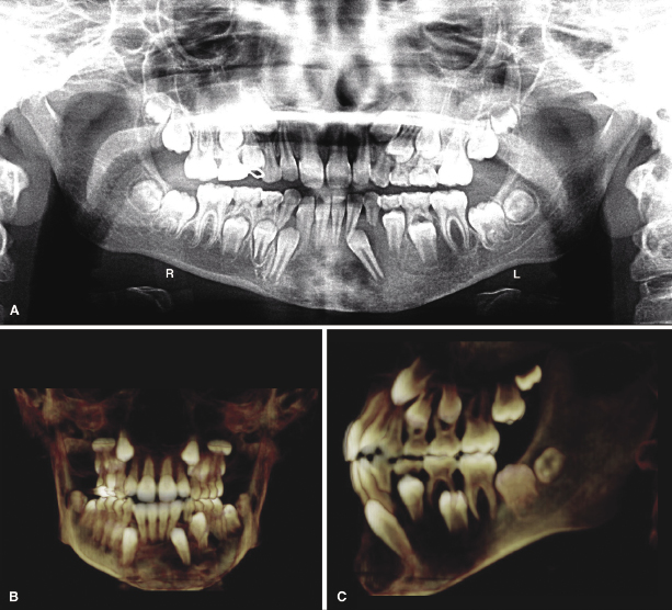
The concept described above is demonstrated clearly in the following example of ectopic mandibular left canine (Figure 8.4A). An attempt to determine the reason for the ectopic mandibular left canine from the 2D panoramic radiograph is likely to be nonconclusive. Also note that the mandibular left primary canine exhibits significant root resorption despite the fact that the permanent canine is not in close proximity to its root. To determine the cause of the ectopic canine, a CBCT scan was taken, which revealed a large radiolucent lesion in the left body of the mandible. The lesion had displaced the permanent canine mesially (Figure 8.4B) and labially out from under the primary canine (Figure 8.4C). After the scan was read by an oral radiologist, it was determined that the lesion was fibrous dysplasia, which had contributed to the displacement of the canine. Because orthodontic movement may be compromised in the presence of active fibrous dysplasia, no orthodontic treatment was recommended. In contrast, had the ectopic canine resulted simply due to a deviated eruption path, the treatment would have been different involving orthodontic retrieval of the tooth.
Acquisition of Additional Diagnostic Information
It has been said that a picture is worth a thousand words. In less than a second, a camera can capture more information within a photograph than the human mind can memorize in the same time frame. When compared with conventional 2D projectional radiographs, the same can be said about CBCT. The volume of information contained within all the voxels of a CBCT scan far exceeds that contained within the pixels of a 2D radiograph (Scarfe & Farman, 2008). These additional diagnostic data are helpful, especially in difficult orthodontic cases when determining the best treatment plan.
As 3D beings living in a 3D world, we sometimes have a difficult time interpreting and understanding the context of structures within a 2D image. Cartographers always have understood this limitation of 2D images. In the book The Nature of Maps, the authors state that “The concept of spatial relatedness is a quality without which it is difficult or impossible for the human mind to apprehend anything” (Robinson & Petchenik, 1976). 3D CBCT imaging removes this limitation by giving the clinician the ability to view teeth and their related structures in their natural context while developing an appreciation of how they relate spatially. In difficult orthodontic cases, this additional information and context well may be the difference between an efficient treatment with an ideal outcome and an unnecessarily long treatment with a poor outcome (Becker et al., 2010b).
Complicated orthodontic cases require more information to derive optimal diagnosis than simple cases do (Mah et al., 2010). Figure 8.5 illustrates a complicated orthodontic case consisting of two fused maxillary incisors and some supernumerary teeth. Due to the amount of crowding, it is difficult to ascertain the locations of the supernumerary teeth and the quality of their roots. A CBCT scan taken to determine the best treatment plan for the patient revealed that a supernumerary right maxillary lateral incisor was located palatal to the fused teeth and a supernumerary left maxillary central incisor was located distal and apical to the erupted left maxillary central incisor (Figure 8.6A,B). To give further context to the positions of the supernumerary teeth relative to the soft tissue, Adobe Photoshop® was used to superimpose the patient’s maxillary occlusal intraoral photograph onto a screenshot of the maxillary dentition rendered from the CBCT scan (Figure 8.6C) and the information used to derive an well-informed treatment plan (Figure 8.6D).
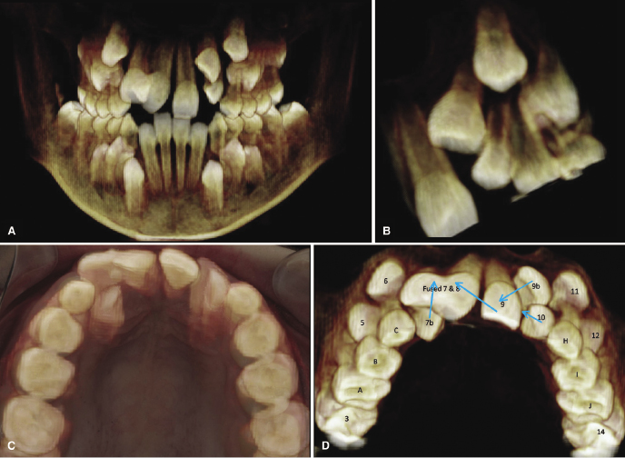
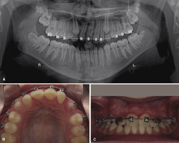
The comprehensive treatment plan depicted in Figure 8.6D involved the extraction of the fused teeth (labeled Fused 7 & 8) followed by the bonding of fixed edgewise-orthodontic appliances. The supernumerary right lateral incisor (labeled 7b) then would be brought labially and the erupted left central incisor (labeled 9) moved mesially across the midline to replace the extracted fused teeth. The supernumerary left central incisor (labeled 9b) then would be moved inferiorly and mesially to replace the left central incisor that had been moved across the midline. At a future date, the erupted left central incisor would require an esthetic bonding or veneer to give it the appearance of the missing right central incisor. This treatment plan would allow the patient to keep a full complement of teeth without the need for dental implants or a fixed prosthesis. After 18 months of active orthodontic treatment, the panoramic radiograph shows the improved positions of the teeth (Figure 8.7A); after 22 months of treatment, the dramatic changes could be appreciated clinically (Figure 8.7B,C).
Increased Treatment Efficiency
The principle that the shortest distance between two points is a straight line can be applied to orthodontic treatment planning. For a large number of simple cases, an orthodontist’s training and experience may suffice to render an efficient treatment plan based on 2D projectional radiographs alone. In cases of facial asymmetries or ectopic, impacted, or supernumerary teeth, however, these traditional projectional radiographs may be insufficient.
The appearance of impacted teeth on panoramic radiographs often can be deceiving (Mah et al., 2003). The goal of taking a CBCT scan in cases of impacted teeth should be to simplify complicated impactions and keep simple impactions from becoming complicated. Often more than one vector of pull is required to bring an impacted tooth in successfully without causing damage to the adjacent teeth (see also Chapter 16). When only one vector of pull is applied, as might happen with inadequate information derived from 2D radiographs, the impacted tooth eventually might be brought into the arch, but may cause iatrogenic root resorption to roots along its path. In some milder cases of impactions, a single vector of pull may be adequate and the CBCT scan simply serves to verify the clinician’s treatment plan while increasing his or her confidence in its outcome (Becker et al., 2010a). Ultimately, the treatment plan is only as good as the diagnosis and the diagnosis is only as good as the clinical and radiographic data derived and the tools used to obtain these.
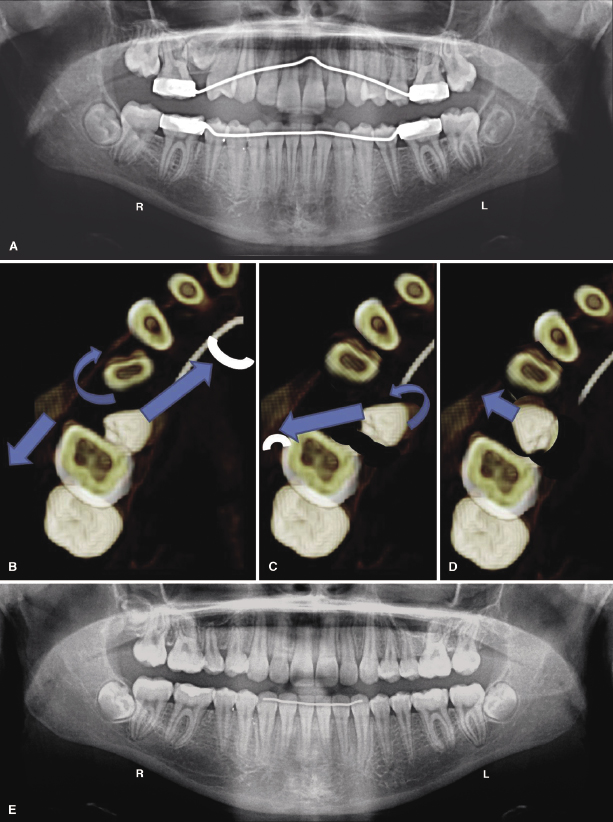
An example of using 3D imaging to create a more efficient treatment plan is demonstrated in the case depicted in Figure 8.8. The panorex (Figure 8.8A) demonstrates an ectopic maxillary right second premolar that is impacted in the mesial furcation of the maxillary right first molar. A CBCT scan was taken to determine the most efficient sequence of vectors by which to deimpact the tooth and bring it into occlusion (Figure 8.8B–D). After only 23 months of active orthodontic treatment, the tooth was brought into functional occlusion without damaging it or the first molar (Figure 8.8E).
Assessing Risk
The clinician must evaluate each case to determine if it will benefit from the diagnostic information derived from a CBCT scan. The risks of exposing the patient to additional radiation should be weighed not only against the benefits of acquiring the scan, but also against those of not obtaining additional diagnostic information. It is easy to overlook the increased risk to which the patient may be exposed if we fail to gather adequate diagnostic information and, therefore, fail to diagnose and plan the treatment properly. For example, the patient may be placed at higher risk of developing generalized root resorption due to unnecessarily long treatment times or localized iatrogenic root resorption due to misplaced vectors. In many cases, the ability to reduce ambiguity, minimize negative sequelae, and acquire more diagnostic information will prove invaluable in planning the most efficient treatment with the most ideal outcome for the patient. However, as discussed elsewhere (Chapter 6), CBCT scanning is not recommended for the sole purpose of screening for pathology or when clinical and/or radiographic evaluation do not support its use.
CBCT Volume Acquisition
Scan Settings
Once the clinician has determined that a specific case will benefit from the additional diagnostic information available from a CBCT scan, he or she then must decide which scan settings to prescribe based on the goal of the scan. Most CBCT systems allow the technician to adjust the height and diameter of the scan volume, voxel size, and duration of the scan in seconds, which corresponds to the number of image frames that will be captured (Molen, 2011; see also Chapter 2).
Field of View Size
The majority of systems allow the technician to adjust the size of the volume being captured; however, some systems allow only one or two pre-set sizes to be used. The size of the volume is referred to as the/>
Stay updated, free dental videos. Join our Telegram channel
VIDEdental - Online dental courses


