7
7
The Recording and Transfer of Orthognathic Planning Data
Introduction
Orthognathic surgery involves three-dimensional movements based on a series of non-surgical and surgical procedures. This is particularly evident in osteotomies which change the occlusal level.
The main planning concerns are:
- prediction of the tooth-bone-soft tissue changes,
- operative reproducibility of the treatment plan, and
- postoperative dentoskeletal stability.
Confounding factors are:
a) planning data transfer inadequacies,
b) the adaptation of the TMJ complex,
c) diversity of surgical skills, and
d) relapse forces.
The definitive preoperative planning process has the following stages:
- clinical estimated measurements,
- impressions,
- occlusal record (squash bite),
- face bow registration,
- face bow transfer to the articulator and mounting of the maxillary model,
- mounting of the mandibular model,
- maxillary model surgery,
- intermediate occlusal wafer fabrication,
- mandibular model surgery, and
- final occlusal wafer fabrication.
These ten processes all require care but are subject to inaccuracies which render fine degrees of planned measurement inappropriate.
With a single jaw mandibular osteotomy, precise model surgery planning using a facebow and anatomical articulator is not required. However, all maxillary and bimaxillary procedures require an accurate transfer of the jaw relationship to the articulator, for surgical planning.
The Planning Process
1. Clinical Measurements
There are inherent difficulties in accurately recording the clinical data. For instance patients may camouflage an occlusal cant by tilting the head and many Class II division 1 patients posture their mandible forwards. There are also important occlusal changes due to the effects of gravity in the conscious patient compared to the loss of muscle tone in the anaesthetised patient.
2. Impression Procedure
a) The impression procedure is more demanding than for standard impressions for dental appliances. Apart from the jaw deformity, malocclusion and postural camouflage, the presence of orthodontic brackets create a challenge for the inexperienced. It is important that the orthdodontic archwire is passive in the brackets at the time of taking the impressions.
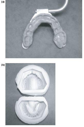
b) The impressions must be taken as near to the surgery as possible. Soft red wax may be applied on the gingival side of the orthodontic brackets to avoid splitting adherent alginate. The application or flow of wax onto the occlusal side of the bracket can obliterate the occlusion. Two full upper and lower impressions which detail all the teeth are taken using irreversible hydrocolloid impression material (Claudius Ash. UK). It is essential to include the terminal cusps of the most posterior molars as failure to record these could lead to unplanned prematurities in occlusal contact at the time of surgery. The impressions are cast in Crystacal R Class III stone plaster (Newark Works, Bowbridge Lane, Newark, Nottinghamshire) and based in plaster (British Gypsum). One set of models is anatomically trimmed for model surgery (Figure 7.1a) and the second angle trimmed as study models (Figure 7.1b).
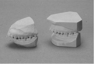
Figure 7.1 (a) Upper and lower models after removing non-anatomical parts, ready to articulate. (b) Standard angle trimmed study models.
3. Recording the Occlusal Relationship
The dental occlusion is dynamic with a three-dimensional envelope of movement which will change with altered patterns of neuromus-cular function such as, postural habits, gravity, the level of consciousness and even psychiatric factors. It is crucial to recognise that preoperative planning is conventionally done on a conscious upright patient using centric occlusal records (CO), i.e maximal intercuspation in the X axis, despite the osteotomy taking place with the mandible in an anaesthetised supine centric relation position (CR), i.e the occlusal retruded position in the Y-axis (Figures 7.2a and 7.2b).
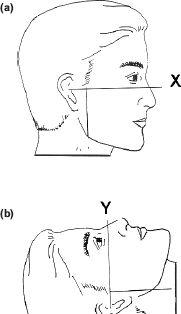
Figure 7.2 (a) and (b) Osteotomies are planned in the upright X-axis but carried out in a supine anaesthetised Y-axis.
A significant difference between the conscious CO and supine anaesthetised CR will produce unexpected discrepancies between the planned and postoperative occlusion, for instance when the osteotomised maxilla is temporarily fixed to the unoperated mandible and rotated upwards and forwards into its planned position for plate fixation. The anaesthetised mandibular CR will give rise to a loss of maxillary advancement which is seen when the patient wakes and sits up with the mandible recoiling forwards.
This may not be apparent in the bimaxillary procedure as the osteotomised mandible is then related to the previously fixed maxilla.
Conversely with a Class III mandibular setback there will be a loss of push back with the conscious upright recoil (Figures 7.3a and 7.3b). This is beneficial in a Class II division 1 mandibular advancement and helps to compensate for any distal relapse.
To avoid these potential problems the osteotomy should be planned from the CR occlusal registration, taken in a relaxed supine patient. Any minor residual CO-CR discrepancies are usually compensated for by proprioceptive adaptation within the envelope of movement of the condyle-disc-fossa relationship.
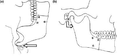
Figure 7.3 (a) Fixation in supine and (b) occlusion when upright.
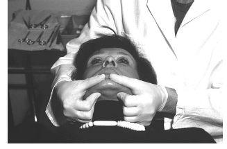
Figure 7.4 The centric jaw relation recording in supine conscious posture using bilateral manipulation technique.
The Registration of Supine Centric Relation
Centric relation is recorded using the bilateral manipulation technique, with the patient in a relaxed supine position and the operator seated behind and with the patient’s head between the two arms. The operator supports the patient’s mandible bilaterally by placing the fingers of each hand below the lower border of the mandible on each side and the thumbs in the depression of the labiomental fold (Figure 7.4). This technique emphasises the “posterior” placement of the condyles in the fossae. With the softened wax occlusal wafer in place the mandible is then guided into the centric relation position.
Appreciation of this plasticity of the condyle-disc-fossa relationship is essential in orthognathic surgery planning.
4. Facebow Recording
a) The facebow is designed to record the relationship of the maxilla to the terminal hinge axis of the patient’s mandibular condyles and a Frankfort-like plane. When transferred to the articulator this becomes the relationship of the maxillary cast to the condylar assemblies of an articulator. Although this axis can vary with posture, when standardised, the facebow/articulator transfer method has proved to be reproducible for orthognathic planning.
a) The Denar (and similar systems) is clinically reliable except where there is gross facial asymmetry. It has a reference point of 43 mm above the lateral incisor edge which defines the anterior point on an arbitary plane within the maxilla (Figure 7.5). The posterior reference point is the bony margin of the external auditory meatus, conveniently located by the facebow earplugs.
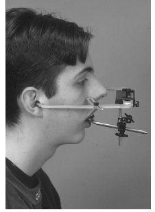
Figure 7.5 Clinical picture of Denar Slidematic facebow with ear plugs for hinge axis point and an anterior reference point 43 mm above central incisor.
Although careful facebow registration shows a high degree of accuracy in the vertical plane there is a wider variation in the horizontal plane which together with the eight other variables in the transfer process, may invalidate the use of small planning movements. Furthermore small variations cannot be controlled surgically nor perceived by the eye. For this reason forward and backward movements of the maxilla are most reliably planned in 3 mm units which also simplifies clinical decision making when translated into minor 3 mm, moderate 6 mm and major 9 mm moves. Similarly vertical movements are more accurately estimated as 2, 4 or 6 mm. impactions again representing minor, intermediate and major defects. The exception to this “3-unit rule” is the cleft palate case with a major iatrogenic disturbance to facial growth.
b) The facebow registration procedure: Facebow ear pieces are placed into the external auditory meati and manipulated until the subject feels equal pressure in both ears. The anterior reference pointer is adjusted to the pre-determined reference mark 43 mm above the incisal edge of the right maxillary lateral incisor and the transfer jig screws are tightened (Figure 7.5).
The facebow bite fork registration can be taken using a silicon based material which gives definition of the occlusal surfaces (Figure 7.6a) and can be easily trimmed with a scalpel should the material inadvertently encapsulate the orthodontic brackets.
Prior to mounting the upper and lower models, silicon moulds of the master casts/models can be prepared (Figure 7.6b). This enables copies of the models to be prepared should damage occur during the construction of the splints and for one to be kept in the patient’s study model box for record purposes.
5. Facebow Transfer to the Articulator and the
Mounting of the Casts
Only the Denar transfer jig and bite fork need to be sent to the laboratory, the facebow does not have to leave the clinic. Unless the procedure is carried out very carefully errors can be introduced when seating the cast into the bite fork indentation and during the subsequent mounting
Stay updated, free dental videos. Join our Telegram channel
VIDEdental - Online dental courses


