3
3
Computerised Cephalometrics for Orthodontic and Orthognathic Planning
Although the basic cephalometric methodology has remained unchanged for many years the application of information technology, to store, display and manipulate cephalometric images has evolved so that;
i) Analysis is significantly faster and more reliable when compared to manual measurement.
ii) Reformation of data enables the simulation of treatment alternatives.
These benefits are seen with direct digital imaging in which the X-ray beam is recorded by photoelectric sensors, such as charged coupled devices, or by a storage phosphor emulsion which is scanned and read by a laser diode (light source). These images require a reduced radiation exposure and can be read as a soft copy on a monitor or a hard copy printed out on transparency film or paper. Indirect digital imaging methods include copying the backlit radiograph film with a digital camera or by computer entry with a flatbed scanner. Both systems provide multiple advantages such as ease of storage, manipulation and enhancement, duplication and the possibility of automated landmark identification.
Regardless of the method used to produce the digital image, the data storage and display are very different from conventional film. Images on a monitor display are composed of a matrix of discrete units called picture elements or pixels. The spatial resolution or clarity of the image is directly proportional to the number of pixels. More pixels mean a sharper image but it also requires the manipulation and storage of more information. The contrast of a digital radiograph is determined by the number of shades of grey which can be displayed. This is known as the bit depth which is determined by the means (algorithm) used to process the image. For example, in a 6-bit image each pixel will have 64 possible values, ranging from black (0) to white (63). An 8-bit image would be able to show 256 shades of grey and 12-bit images can show 1024 shades. Most dental radiology applications use 8-bit images but newer technologies are available that allow for 12-and 16-bit images.
A limiting factor when viewing digital images is the monitor itself. Typical monitors have 72-96 pixels per inch (ppi) display resolution and are capable of 625 digital (raster) lines. The full potential of any image with higher resolution can only be displayed with clarity after being printed as a hard copy. For digital images equal to film quality, a monitor capable of displaying 2048 raster lines would be needed. In addition to being expensive, it is difficult for computers to refresh (handle) this number of lines without creating a “flicker” in the image.
Digital images are further limited by the monitor’s contrast capabilities. Analogue films have an almost infinite or continuous greyscale. As stated, most dental digital images are viewed with only 256 shades of grey. The problem is compounded by the fact that digital images are often displayed more brightly than with analogue film which tends to reduce the already inferior greyscale resolution. It is important to bear in mind that the number of shades of grey or bit depth needed is dependent on what is being diagnosed from the image.
Once the spatial resolution and contrast have been optimised, the capacity of the human eye becomes the limiting factor. The smallest detail the human eye can resolve is approximately 0.1 mm by 0.1 mm. Therefore, we are unable to appreciate more detail in any image with a smaller pixel size. Conversely, images with pixels of a much larger size, for example 0.7 mm by 0.7 mm, may seem blurred (Figure 3.1). A pixel size of 0.1 mm should be equal to X-ray film when identifying landmarks on cephalometric radiographs.
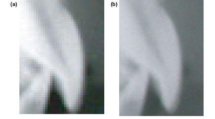
Figure 3.1 These digital images are identical except for spatial resolution. (a) The left image has a pixel dimension of 0.084 × 0.084 which is at the limit the human eye can resolve. (b) The pixel dimension of the image on the right is 0.35 × 0.35. Note the fuzzy appearance with loss of definition.
Digital imaging technology is becoming the standard of care. The advantages of storage, portability, ease of duplication, manipulation and communication outweigh the disadvantages. However, with these advantages come responsibilities. The ease of data manipulation opens the opportunity for record tampering. The ease of duplication and portability create problems of confidentiality. The DICOM (digital imaging and communication in medicine) Standards have been developed to attain compatibility and to ensure workflow efficiency between imaging systems and other information systems. The standards also address security in record transmission and storage as well as record “locking” or digital signatures. The dedicated clinician must be vigilant of changes in hardware, software and responsibilities for their use.
Treatment Planning with Digital Images
Orthognathic treatment planning requires some method of predicting the anticipated outcome. In clinical practice this has been based on experience and intuition. Digital simulation is based on a tracing prepared from landmarks identified on a standardised lateral cephalometric radi/>
Stay updated, free dental videos. Join our Telegram channel
VIDEdental - Online dental courses


