6
Bar Attachments
BAR MATERIALS
Bar attachments can be prefabricated type IV gold like the original 1.6mm Dolder Bar. Prefabricated type IV gold bars should be soldered to the abutments with a low fusing solder. The other types of bars come in castable pre-milled plastic patterns. These bars are available in 0, 2, and 4 degrees for telescopic milled restorations. The bar castings should only be made with hard alloys. A minimum Vickers hardness of 200 and at least 95,000psi ultimate tensile strength is required. Non-precious alloys are contraindicated for implant reconstruction.
Examples of Castable Bars
- Round bar
- Plastic Dolder Bar
- I bar
- EDS bar
- Hader Bar
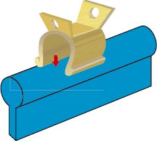
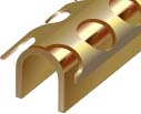
Bar clips or riders are available in different materials and configurations. The metal clips/riders are fully adjustable. Plastic Hader/EDS clips are non-adjustable, but they can easily be replaced at chair side. Use of a metal housing with Hader/EDS plastic clips is strongly recommended.
Classification of Bar Attachments Based on Cross-Sectional Shapes
- Round (Figure 6.1)
- Egg shaped (Figures 6.2 and 6.3)

- Parallel sided “U” shape (Figure 6.4)
Classification of Bars Based on the Nature of Their Resiliency
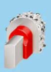
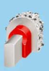
- Bar joints (resilient) provide vertical and/or hinge resiliency (Figure 6.5)
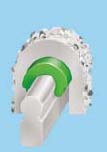
- Bar units (non-resilient) (Figure 6.6)
Factors that Influence the Flexibility of the Bar
- Length of the bar between the two implants
- Number of implants that support the bar
- Height of the bar
- Physical properties of the alloy
- Magnitude of the masticatory loads
FUNDAMENTALS OF BAR ARRANGEMENT
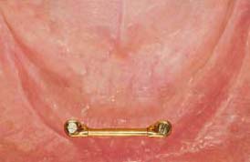
As a general rule if a single bar is being utilized, the ideal length should be 20–22mm to accommodate two clips/riders. This means the center of the implants should be 24–26mm apart if standard diameter 4mm implants are being used (Figure 6.7 and 6.8).
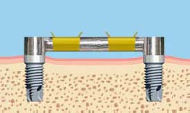
If the two implants are too close, the short bar cannot provide enough retention and stability for the overdenture (Figure 6.9).
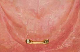
This distance, however, depends on following conditions:
- Size and curvature of the mandibular arch
- Type of attachment assembly
If the implants are placed too far distally, a straight-line bar will interfere with the tongue space and create problems in fabricating the prosthesis, also it will be at risk of bending (Figure 6.10 and 6.11).
If the bar has been positioned diagonally, it will not allow friction free anterior hinge movement of the prosthesis. This condition creates excessive torsional loading on the supporting implants (Figure 6.12).
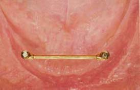
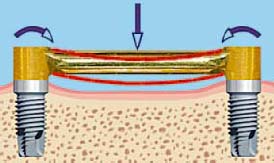
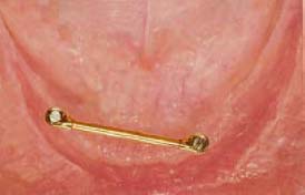
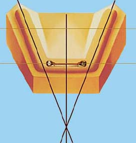
As a general rule the bar should be perpendicular to the line that bisects the angle formed by the two posterior mandibular arch segments (Figure 6.13).
Vertical Relationship of the Bar to the Alveolar Ridge
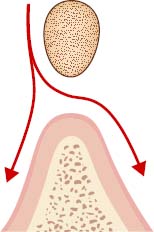
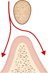
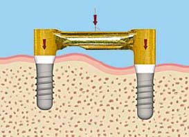
- Wide Gap: There is 2mm or more between the bottom of the bar and the soft tissue (Figure 6.14). This distance allows easy passage of saliva and food particles as well as cleaning tools. Hygiene maintenance in this situation is very easy.
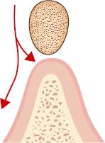
- Small Gap: There is 1mm or less between the bottom of the bar and the soft tissue (Figure 6.15). This distance will cause plaque and calculus accumulation and it would be very difficult to perform oral hygiene maintenance.
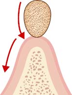
- Compression of the Mucosa by the Bar: This causes hyperplasia of the gum (Figure 6.16). It is impossible to clean underneath the bar. The bar should be replaced or modified to solve this problem.
Sagittal Relationship of the Bar to the Alveolar Ridge
The bar should be positioned directly above the crest of the ridge (Figure 6.17). This position makes it easy to clean the bar and fabricate the prosthesis above the bar.
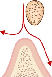
If the bar is positioned lingual to the crest of the ridge, it will interfere with tongue space and its function and the patient’s speech (Figure 6.18). This problem is a common situation in patients with a narrow and pointed alveolar ridge. One way to prevent this situation is to relocate the bar further anteriorly. Another solution is to use individual attachments.
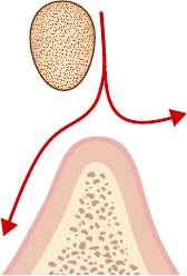
If the bar is positioned labial to the crest of the ridge, it will interfere with lip support (Figure 6.19). Both of these scenarios will make fabrication of the prosthesis very difficult.
Sagittal Relationship of the Bar to the Hinge Axis
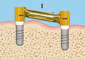
It would be ideal if the anterior bar in the edentulous mandible were parallel to the hinge axis. However, this relationship is another reference for better positioning of the bar and this orientation can’t be achieved in every case. This rule has been followed by many clinicians, but no studies have supported this claim. The long term study (5–15 years) by Oetterli, Kiener and Mericske-Stern analyzed the influence of placing the bar parallel to the hinge axis on peri-implant parameters, including the clinical attachment level. The outcome as far as the type of retention, splinted versus unsplinted, was also assessed. No significant correlations were found.
Sometimes the anatomical shape of the alveolar ridge will not allow the surgeon to position the implants with the bar parallel to the hinge axis (Figure 6.20 and 6.21). In this situation, the lab technician and restorative doctor can modify the bar design to achieve this goal.
Anterior-Posterior Distance Rule
The anterior-posterior distance rule is good for determining the distal cantilever extension of the bar or distal extension of the hybrid (fixed detachable) prosthesis from the most posterior implants.
- Draw a line through the center of the most posterior implants on each side of the arch (Figure 6.22).
- Draw another line through the center of the most anterior implants on each side of the arch.
- The distance between these two lines is the Anterior-Posterior spread (A–P distance).
- Generally, the distal cantilever should not exceed more than half of the Anterior–Posterior distance.
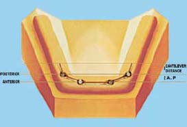
If the patient has a small mandible, with limited room for four implants, putting the distal implants as far back as possible to the mental nerve can enhance the A–P distance. In addition, the anterior implants should be brought forward as far as possible. These steps will improve the A–P distance to ensure that the basic biomechanical rules are not violated. The maximum cantilever in these cases is generally 8–12mm.
If the patient has a square arch, the implants will be in a straight line in the anterior segment of the mandible. In this situation, any cantilever design must be avoided since the A–P distance will be non-existent or significantly reduced. Resilient bar assemblies are suggested for these patients. The prosthesis should be implant and tissue born so that the buccal shelf and retromolar pad will receive a share of the occlusal load.
To minimize the compressive load on the bar, the denture base can be relieved in the area over the distal extensions.
Guidelines for Denture Base Extension
- Mainly Tissue Supported Implant Overdenture: The borders of the overdenture in the anterior area should not extend to the end of the sulcus. There should be minimum extension in the anterior region but maximum extension in stress bearing areas such as buccal shelves. The denture base should extend distally onto the retromolar pads and lingually onto the mylohyoid ridge.
- Tissue-Implant-Supported Overdenture: The borders of the overdenture are significantly shorter than conventional dentures; however, they can’t be eliminated since this type of prosthesis is still partly tissue supported.
- Fully Implant-Supported Overdenture: Since the prosthesis is completely implant born, flanges can be eliminated.
HADER BAR
In 1973, Helmut Hader, master technician and dental manufacturer, developed a unique attachment system that even today is mainly known in the USA as Hader Bar and Hader Vertical. The Hader Bar is a semi-precision bar attachment that provides hinge movement as long as a single Hader Bar has been utilized in an attachment assembly design. The function of this bar is based on the mechanical snap retention concept (Figures 6.23 and 6.24).
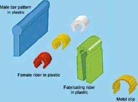
Three color-coded clips/riders are available with three retentive strengths. In order from the least to most retentive, they are white, yellow, and red. Use of a metal housing with the Hader plastic clips/riders is strongly recommended. In addition to plastic clips/riders, the option of adjustable gold alloy clips/riders is available (Figures 6.25 and 6.26).
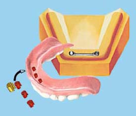
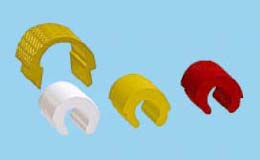
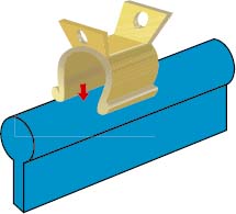
Fabrication Procedures for a Castable Hader Bar Attachment with Plastic Clips/Riders
Fabrication Procedures for a Castable Hader Bar Attachment with Gold Alloy Clips/Riders
Stay updated, free dental videos. Join our Telegram channel

VIDEdental - Online dental courses


