CHAPTER 4 Selection of the Proper Implant
DIAGNOSTIC METHODS
Examination
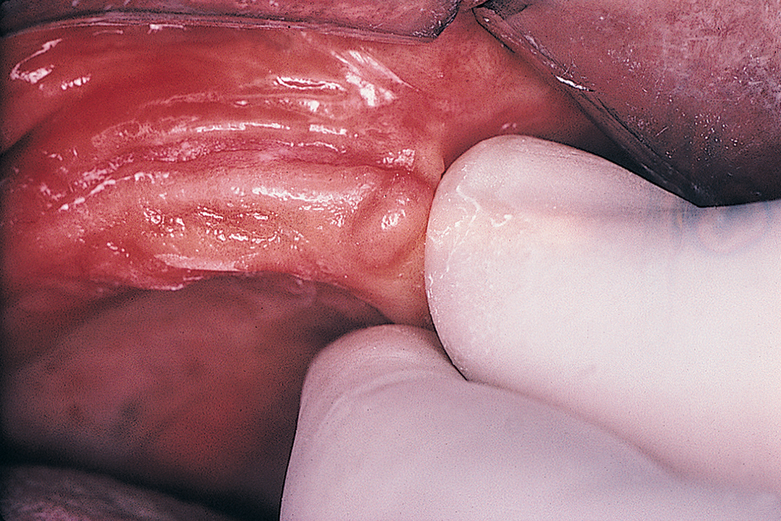
The next step in the diagnostic sequence is manual palpation. Using the thumb and index finger, the examiner palpates the edentulous ridges (Fig. 4-1), assessing the firmness and thickness of the soft tissues.
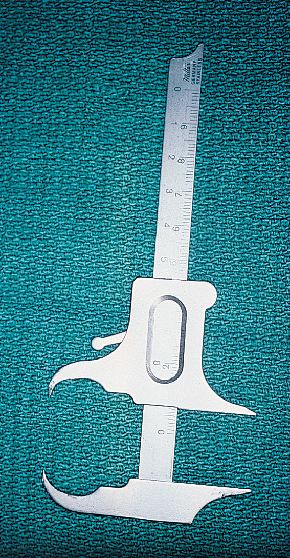
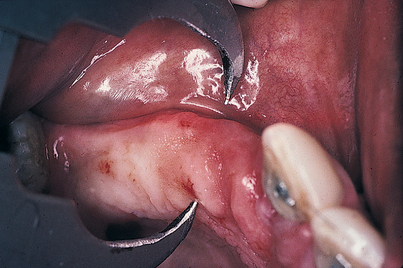
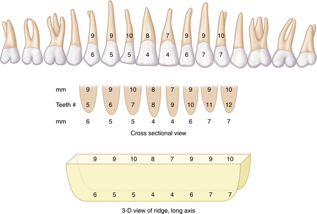
A determination of the uniformity of thickness over the entire height and length of the underlying bone is important. Concavities and convexities may be present that might not be evident on visual or digital examination. To clarify and define the presence and extent of such irregularities, the practitioner should prepare to sound the bone (or delineate the shape by closed examination). A 30-gauge needle is used to deposit a small amount of local anesthetic along the labial and lingual aspects of the edentulous areas under consideration for implant sites. A sharpened periodontal probe then is used to measure the thickness of the soft tissue at several points. These and all other calibrations should be recorded on a diagnostic chart. Next, a sterilized Boley gauge with sharpened beaks is used to puncture the soft tissues by squeezing the calipers directly through tissue to bone (Figs. 4-2 and 4-3). The beaks should oppose one another so that an accurate reading results. This produces a measurement of bone width at varying ridge sites. By obtaining measurements from superior to inferior and from medial to distal at 5-mm intervals, the clinician develops a topographic map of the soft and hard tissue dimensions of the areas into which implant placement is intended. When these measurements are used, an accurate, three-dimensional representation of the operative site can be sketched (Fig. 4-4).
Study Casts
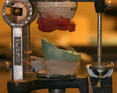
Next, a U-shaped, softened sheet of wax is fixed to the bite fork. The patient’s mouth should be closed in centric relationship lightly into the wax so that indentations are made by the cusp tips of the teeth. For edentulous patients, stable base plates are used. The maxillary wax rim is attached to the fork, and the patient is guided into a centric closure of the proper vertical dimension. With the bite fork held in place by the patient’s teeth, the facebow is assembled. The axis locators should be allowed to contact the marks on the skin, and the assistant should tighten the set screws, locking the bite fork, locator, and facebow in place. The axis locators are then loosened; if the system is stable, the locator’s tips will not move. The patient may then open the mouth, and the entire assembly can be removed.
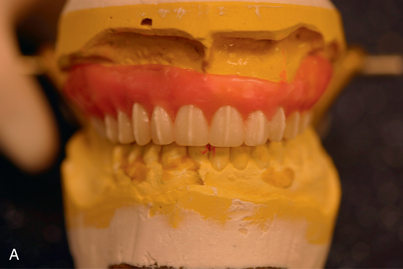
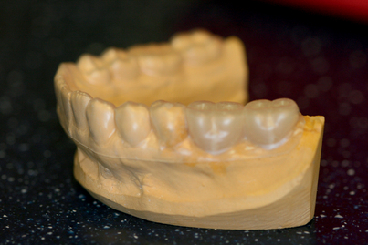
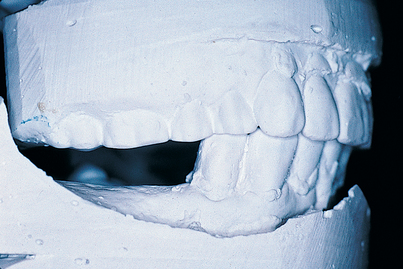
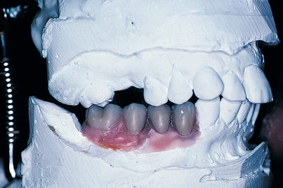
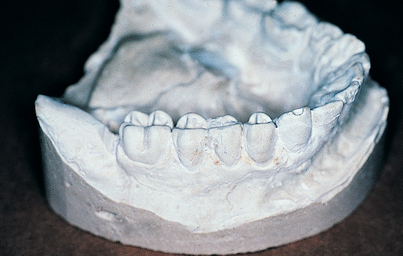
The implantologist should study the mounted casts with respect to interocclusal distances, existing occlusal relationships, and arch forms (Fig. 4-5). If a distance of 7 mm or less is found between the potential host site and the opposing natural or prosthetic occlusal surfaces (Fig. 4-6), an implant cannot be used unless additional space can be created by the following methods:
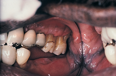
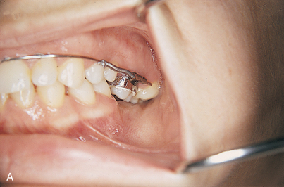
FIGURE 4-6. One cause of insufficient intermaxillary distance (7 mm or less) is supereruption of the opposing dentition. This problem may be solved by extraction, endodontic therapy, occlusal equilibration, an increase in the vertical dimension, or subapical en bloc resection (see Fig. 4-7).
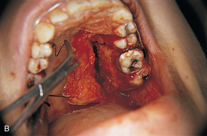
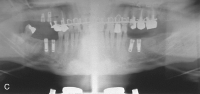
With edentulous posterior mandibular quadrants, extrusion of the maxillary molars or premolars directly opposing the area often is a factor. If significant periodontal disease is not present, the alveolar ridge actually is thrust downward, carrying the teeth with it. In such cases, an en bloc segmental osteotomy can be performed to intrude the problematic area, increasing the intermaxillary space (Fig. 4-7).
If the articulation indicates crossbite or ridge procumbency, the implantologist must determine that the angulation of the implants will permit the final prosthesis to be in functional position. Implants at greater than 35-degree angulations from the long axis of the ridge present significant aesthetic and functional problems. If an angle greater than 35 degrees is created, forces are exerted that may be detrimental to the longevity of implant host sites. For this reason, some excellent ridges may be considered questionable if the angulation places implants in compromised positions. Custom casting using wax patterns for cementable abutments can be done. In addition, some implant designs (i.e., Straumann, Nobel Biocare) have abutments with angles of 15 degrees or even 30 degrees. However, seating these to the proper alignment requires special skills (see chapters 21 and 27).
Radiology
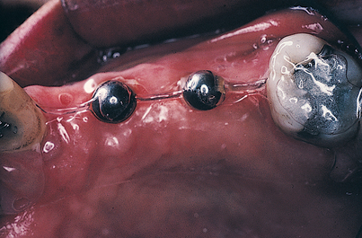
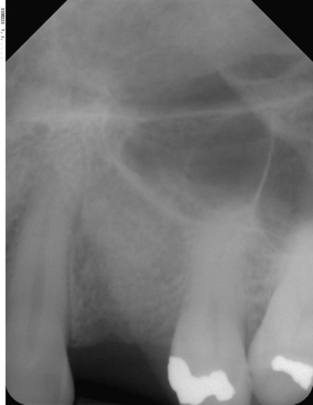
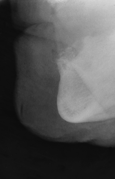
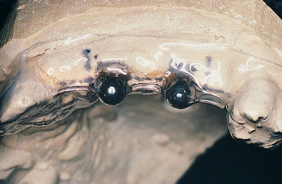
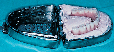
FIGURE 4-12. The trimmed Omnivac template is put in position in the patient’s mouth, and long cone radiographs are taken (see Fig. 4-13).
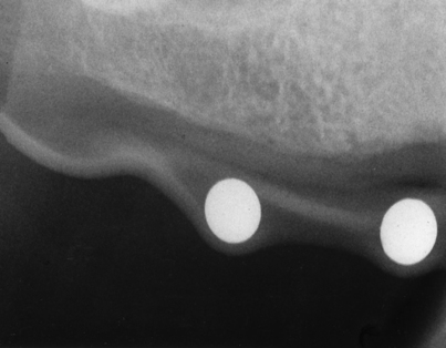
FIGURE 4-13. To verify accuracy, the diameter of the spheres on the radiograph must be compared with their actual size (5 mm).
where rs is the radiographic sphere measurement, rm is the radiographic bone measurement, rx is the actual bone measurement sought, and 5 is the actual sphere measurement.
The Omnivac guide is retained, because at the time of surgery, the spheres can be removed; the template then can be sterilized, and after the soft tissues have been reflected, it can be used as an implant site locator (this technique is explained in more detail in Chapter 9).
Cone Beam Volumetric Tomography
All cone beam scanners have preinstalled software for image manipulation and added image functionality. For example with multiplanar reformatting (MPR), three-dimensional volume data usually are acquired in the axial plane (top to bottom slices). MPR creates sagittal, coronal, and transverse images from those axial images (basically, front view and side view slices). The images are displayed in formats that allow effective visualization of section to section change in the scanned structure. MPR images are available in all preinstalled cone beam scanner software. The software also allows the practitioner to take measurements on the slices and measure density in Hounsfield units.
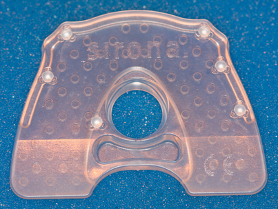
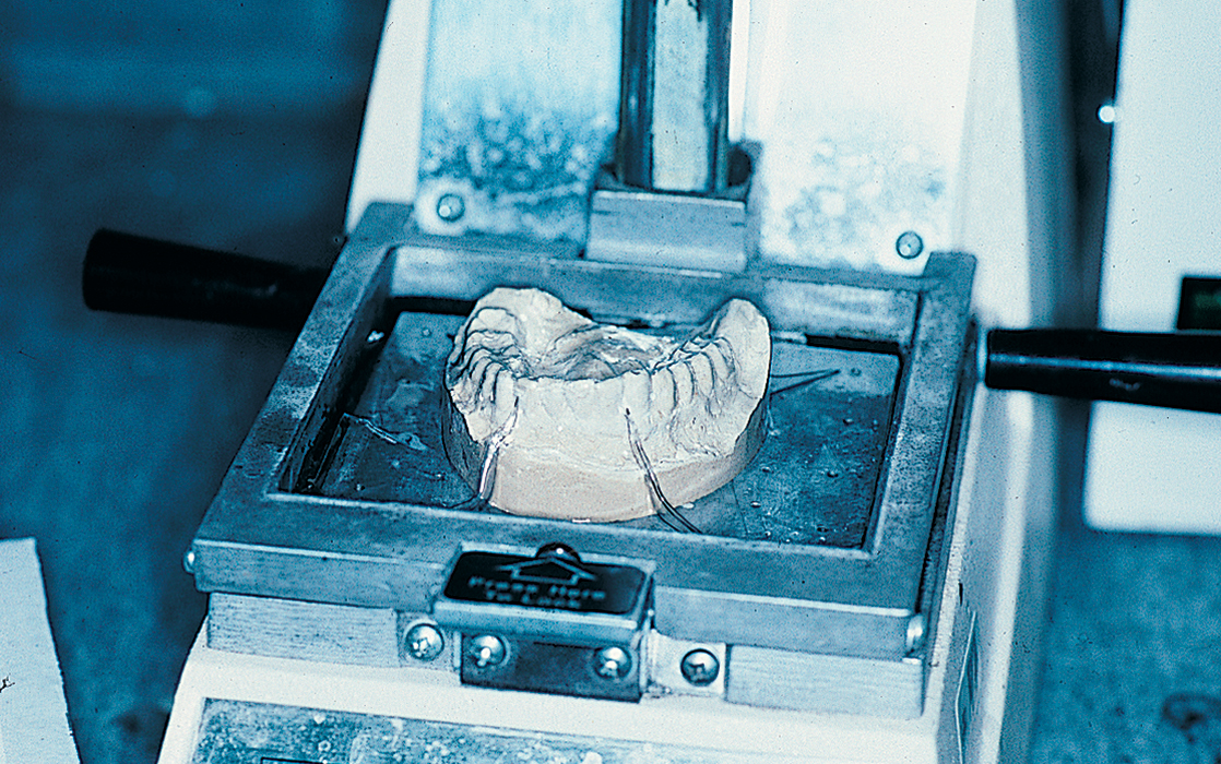
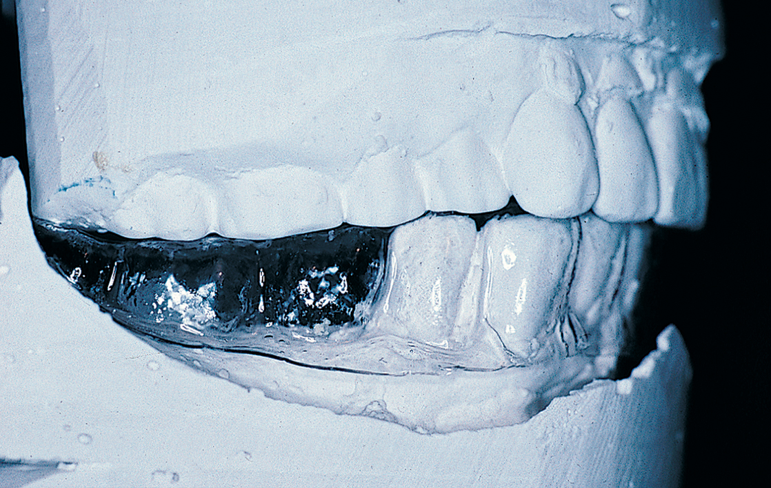
A radiographic bite plate contains fiduciary radiopaque reference markers and produces a patient-customized scan stent (Fig. 4-14). The dental technician manufactures a scan stent by fusing the radiographic bite plate with a vacuum-form pickup of the radiopaque die (25% barium sulfate)–impregnated cold-cure acrylic prosthetic mockup. This radiographic template is worn by the patient during a scan and is based on the bite plate and a diagnostic prosthetic workup on the gypsum model (Fig. 4-15). After the scan, the scan volume is reconstructed on the computer (Fig. 4-16). Based on the patient’s three-dimensional radiography, the implantologist can do the implant planning with the included (i.e., GALILEO Simplant) or third party (i.e., Materialize-Simplant, Nobel Biocare–Procera) right on the computer.
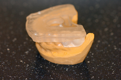
FIGURE 4-15. Galileos radiographic template sitting on the study cast as it would in the patient’s mouth.
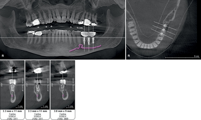
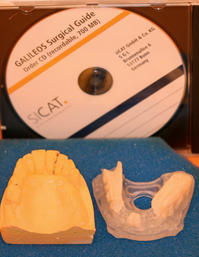
If the procedure will involve the lower jaw, the implantologist may want to mark the inferior alveolar nerve as the first step (Fig. 4-17). The implant planning data then are stored on a removable computer medium (e.g., CD-ROM). The planning data, the scan stent, and the gypsum model of the surgical area, along with clear, detailed written instructions on the surgical drill guide order form, are sent to the laboratory that will fabricate the surgical drill guide (e.g., SiCat, Nobel Biocare, Biomet-3I) (Fig. 4-18).
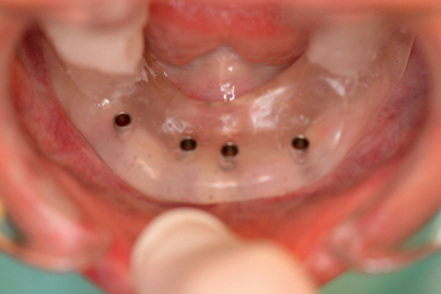
The laboratory manufactures a surgical drill guide based on the implant planning data and the scan stent. The guide is equipped with a pilot drilling system, a sleeve-in-sleeve system, or the outer sleeves of established surgical systems (Fig. 4-19).
RADIOGRAPHIC EVALUATION
Airway Space Analysis
The CBCT scanner has a compact size, is easy to use and allows easy patient positioning, has a fast acquisition speed (6 to 14 seconds), and involves a relatively low dose of radiation; all these factors make it ideally suited for imaging of the craniofacial region, including dental structures. This modality is emerging as the imaging standard of care for a number of diagnostic assessments of bony components of the face.
Computed Tomography
Three-dimensional imaging allows visualization of any area within the parameters of the scan. CT scanners provide a variety of views by making 0.5-mm slices through the bone, which are stacked by the program’s software like a deck of playing cards. When the three-dimensional subject is complete, the computer reformats it into coronal, cross-sectional, or panoramic images, which also are sliced. This program ensures that the surgeon is not confronted with any surprises during surgery. The amount of available bone (or lack of it) may be plotted to the millimeter. The amount of bone beneath the maxillary sinus and nasal cavity may be charted for width and height, and the density of bone may be assessed. In the mandible, the exact location of the mandibular canal in even its most tortuous course may be plotted before surgery.
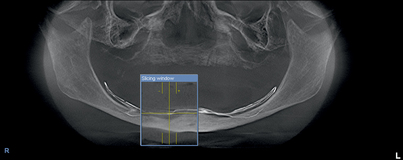
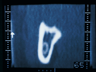
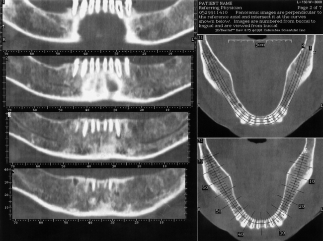
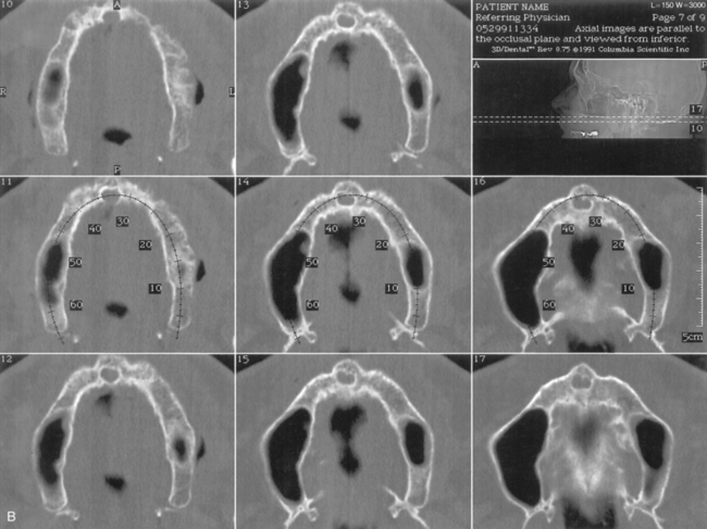
The scanner produces a series of images made from horizontal slices (Fig. 4-20). Each exposure is 0.5 mm wide. When the series of cuts is completed within the prescribed perimeters, they are stacked by the computer. The program uses this reconstituted three-dimensional structure to supply images made in the cross-sectional (Figs. 4-21 and 4-22), panoramic (Figs. 4-23 and 4-24), and occlusal modes (Figs. 4-25 and 4-26). These images may be interpreted, area by area, so that the arch in which the implants have been planned can be plotted to the millimeter in width and depth. In addition, exact locations of all vital structures are readily identified by using the images, which the process presents in 1-mm sections.
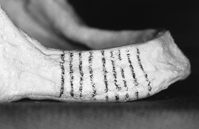
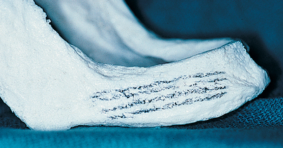
FIGURE 4-21. The vertical lines indicate the cross-sectional planes, or “cuts,” the CT software makes available.
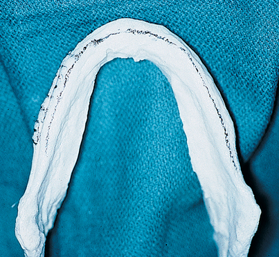
FIGURE 4-23. A panoramic view is another valuable image produced by CT scanning. Usually five slices are made available, from buccal to lingual. This mandibular model shows the middle level of the five slices marked by pencil (see Fig. 4-24).
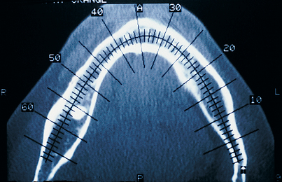
FIGURE 4-25. An occlusal view made in the midmandible. The numbered cross-hatching indicates the cross-sectional images, each 1 mm wide (see Figs. 4-22 and 4-43).
Currently, software systems are available (Dentascan, Galaxis) that allow the dentist to reformat axial images in the office and superimpose appropriately sized implants on them (Fig. 4-27).
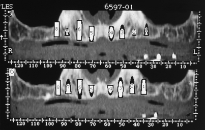
FIGURE 4-27. The Dentascan program allows computerized superimposition of implants of specific dimensions directly on images. The computerized implants may be placed on both cross-sectional and panoramic views (see also Fig. 4-54).
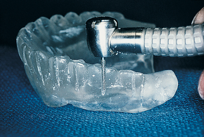
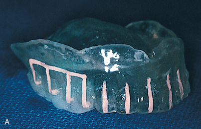
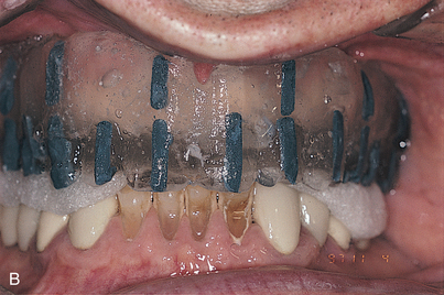
The proper plane of occlusion is established in the splints, and nonmetallic radiopaque markers (gutta percha or barium sulfate 25%) are placed parallel to and at the plane of occlusion. These markers tell the radiologist how to orient the patient’s head for the study. They also ensure that the angle at which the cross sections are reformatted through the scanned arch is 90 degrees to the occlusal plane. The accuracy of measurements taken from the scan depends on the orientation of the preliminary film, or scout film. Consequently, accurate placement of the opaque occlusal plane markers is essential. The radiography technician must position the patient’s head so that the scout film demonstrates its orientation lines parallel to the marker (see Fig. 4-42).
Methods of Radiographic Splint Fabrication
Edentulous Arch
The following steps make up the process for a patient with an edentulous arch.
Partly Edentulous Arch
The steps for a partially edentulous are as follows.
Stay updated, free dental videos. Join our Telegram channel

VIDEdental - Online dental courses


