4
Intraoral Digital Imaging
Intraoral radiography with digital sensors should be considered the primary radiographic technique in endodontics. Should digital intraoral radiography not provide adequate diagnostic information for the clinician, occlusal radiography and small field, high-resolution cone beam computed tomography (CT) may be used to supplement periapical images. The purpose of this chapter will be to review intraoral digital imaging sensor technology as it applies to endodontics.
Intraoral Digital Imaging
Intraoral imaging is performed using an alternating current (AC) or direct current (DC) X-ray unit with a focal spot size of between 0.4 mm and 0.7 mm, operating between 60 kVp and 70 kVp using a filament current of between 4 mA and 7 mA, and an X-ray target-to-exit distance of at least 12 in.
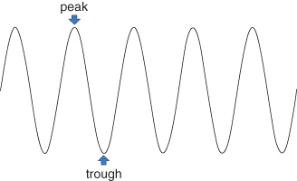
Contemporary X-ray systems use either an AC or DC generator in the X-ray housing to produce X-rays. The AC waveform can be visualized as being sinusoidal in nature with regular peaks and troughs (Figure 4.1), and a periodicity of 1/60th of a second or 60 Hz. This means that the waveform repeats itself between successive peaks or troughs, every 1/60th of a second. When the waveform reaches its peak, electrons flow from the tungsten filament inside the X-ray tube to the tungsten target where the X-rays are generated. X-rays are generated throughout the entire positive cycle of the waveform, every 1/120th of a second; during the trough, no X-rays are generated.
Figure 4.1 Active current (AC) waveform. This trace demonstrates the peaks and troughs of the AC waveform. The duration of one cycle of the waveform (peak-to-peak or trough-to-trough time) is 1/60th of a second. The frequency of the waveform is therefore 60 Hz.
There are inherent inconsistencies or errors in the timing systems of X-ray machines, and these may be more pronounced with shorter exposure times. For less sensitive film-based image receptors that in the past relied on longer exposure times, the pulsed nature of the X-ray beam was not significantly impacted by inconsistencies in the timing or generation of each waveform. For more sensitive film-based or digital sensors that use very short exposure times, inconsistencies may be more noticeable. For example, for very short exposure times of say 0.1 or 0.2 second, an inconsistency of the waveform that disrupts X-ray production for 0.02 or 0.03 second may substantially reduce image density. In an attempt to lessen this problem, manufacturers have developed DC or constant potential systems that incorporate technology that increases the frequency of the AC waveform from 60 Hz to near 70,000 Hz (i.e., 70 kHz) (Figure 4.2, black line). Consequently, X-ray generation becomes almost steady state (Figure 4.2, red line). DC systems also theoretically contribute to lower effective radiation doses. Because the voltage generated is always at or near its peak, less lower energy, less-penetrating, or “soft” radiation is produced, and consequently, less radiation is absorbed by superficial tissues such as skin. The practical decrease in patient dose has not, however, been well documented.
Figure 4.2 Constant or direct current (DC) X-ray tube heads increase the frequency to some 70,000 Hz (70 kHz) (black trace). As a result of the ultra-high frequency of the waveform, the output of radiation attains an almost steady-state peak.

The size of the focal spot or tungsten target may also impact the quality of the image. A smaller focal spot diameter (0.4 mm vs. 0.7 mm) theoretically produces less divergence of the X-ray beam from focal spot to receptor. A less divergent X-ray beam produces less penumbra or edge unsharpness around an object, creating an image that is theoretically sharper with better defined edges. Other factors that affect X-ray beam divergence include the distance between the focal spot and the exit point of the X-ray beam from the X-ray collimator and collimator shape. Some intraoral X-ray systems employ distances as short as 8 in. Shorter focal spot-to-exit point distances also create a more divergent X-ray beam in comparison to those that use longer collimation, for example, 12 or 16 in. Although 16-in. collimators may be difficult to find, most intraoral X-ray machine manufacturers have, as an option, collimators that result in a 12-in. focal spot-to-exit point distance.
Rectangular collimation in which the exit field of the X-ray beam is not substantially larger than the size of an American National Standards Institute (ANSI) number 2 size sensor limits the size of the X-ray field on the patient. The use of rectangular collimation limits not only reduces the skin entrance dose of the X-ray beam by as much as two-thirds, which is substantial, but the amount of X-ray scatter as well (Velders et al., 1991).
Both operating peak kilovoltage (kVp) and filament current (milliamperage [mA]) affect the quality and/or quantity of the X-ray photons produced. While increasing both peak kilovoltage and milliamperage increases the total bolus of X-ray photons produced, only peak kilovoltage affects the quality of the photons; that is, the distribution of lower energy, less penetrating photons and higher energy, more penetrating photons. As well, higher peak kilovoltage X-ray beams impact on image contrast by affecting the number of gray values that are visible. For viewing subtle changes in tooth or bone mineralizat/>
Stay updated, free dental videos. Join our Telegram channel
VIDEdental - Online dental courses


