4 Clinical Case Presentations Based on Different Implant Placement Protocols
Immediate Implant Placement (Type 1)
4.1 Immediate Placement of an Implant in a Maxillary Right Central Incisor Site
J. R. Beagle
A 30-year-old female patient was referred to the office for the treatment of tooth 11.Her chief concern at the initial visit was to inquire, “Why is my tooth pink?” Upon clinical examination, it was determined that tooth 11 had a previous history of trauma and that the clinical crown had become noticeably pink in color as a result of internal resorption (Fig 1).
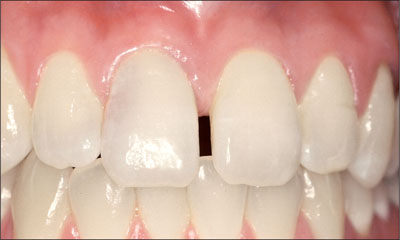
Fig 1 A 30-year-old Caucasian woman presented with internal resorption of tooth 11. A high-scalloped, thin tissue biotype is clinically evident.
This diagnosis was confirmed radiographically, indicating a large radiolucency involving the central and distal portions of the clinical crown (Fig 2).
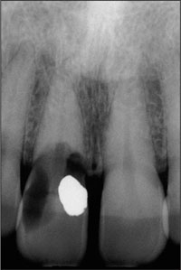
Fig 2 Periapical radiograph of teeth 11 and 21, illustrating the resorption defect associated with tooth 11.
It was determined that restoration of this tooth was not possible, and that extraction was indicated. The presence of a mid-line diastema, which the patient wanted to reproduce, directed the treatment plan for tooth replacement utilizing a dental implant. Her medical and dental health, including a periodontal and occlusal analysis, indicated her to be a good candidate for dental implant surgery and restoration. Although she presented with a high lip line and a thin tissue biotype, an immediate placement (Type 1) technique with a conventional restorative loading protocol was recommended to accelerate her rehabilitation.
The clinical and radiological findings, in combination with the patient’s treatment expectations, led to an esthetic risk profile summing up to a medium to high esthetic risk (Table 1)
| Esthetic Risk Factors | Low | Medium | High |
| Medical status | Healthy, cooperative patient with intact immune system | Reduced immune system | |
| Smoking habit | Non-smoker | Light smoker (<10 cig/d) | Heavy smoker (≥ 10 cig/d) |
| Patient’s esthetic expectations | Low | Medium | High |
| Lip line | Low | Medium | High |
| Tissue biotype | Low-scalloped, thick | Medium-scalloped, medium thick | High-scalloped, thin |
| Shape of tooth crowns | Rectangular | Triangular | |
| Infection at implant site | None | Chronic | Acute |
| Bone level at adjacent teeth | ≤ 5 mm to contact point | 5.5 to 6.5 mm to contact point | ≥ 7 mm to contact point |
| Restorative status of neighboring teeth | Virgin | Restored | |
| Width of edentulous span | 1 tooth (≥ 7 mm) | 1 tooth (<7 mm) | 2 teeth or more |
| Soft-tissue anatomy | Intact soft tissue | Soft-tissue defects | |
| Bone anatomy of alveolar crest | Alveolar crest without bone deficiency | Horizontal bone deficiency | Vertical bone deficiency |
Prior to the initiation of the dental implant surgery, mounted diagnostic study casts were obtained and a surgical stent was fabricated. The immediate implant surgical procedure for tooth 11 was carried out as described in Beagle (2006) (Figs 3 to 8).
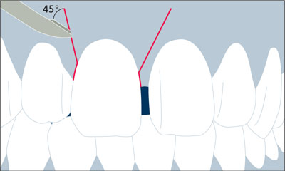
Fig 3 Labial view of the course of the initial incision. Note the scalpel blade being positioned at a 45° angle to the buccal soft tissues for the vertical releasing incisions.
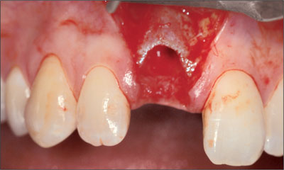
Fig 4 Buccal view of the initial incision.
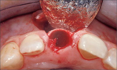
Fig 5 Occlusal view of the initial incision.
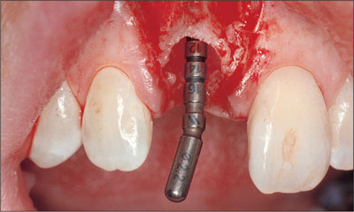
Fig 6 Buccal view following preparation with a 2.2-mm twist drill.
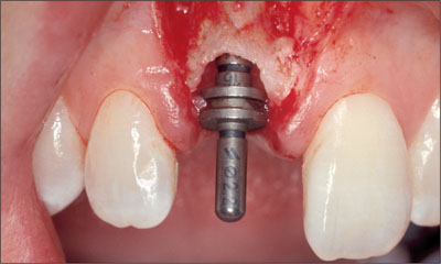
Fig 7 Buccal view following preparation with a 2.8-mm twist drill.
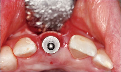
Fig 8 Occlusal view following preparation with a 2.8-mm twist drill.
Excellent primary stability was obtained using a Straumann Tapered Effect implant (endosteal diameter 3.3 mm, length 12 mm, Regular Neck prosthetic platform 4.8 mm) (Figs 9 to 11).
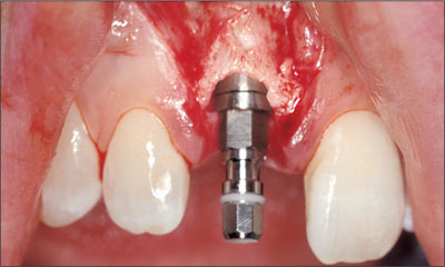
Fig 9 The implant in place with the transfer piece still attached, indicating the correct mesial-distal relationship, as well as the correct occlusal-cervical relationship.
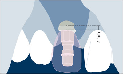
Fig 10 The future soft-tissue margin at the implant crown served to place the implant shoulder in the ideal coronoapical position.
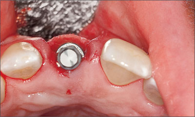
Fig 11 Occlusal view of the implant with the transfer piece attached, indicating the correct buccal-lingual position.
Grafting of the horizontal defect dimension and thin labial plate was performed using autogenous bone and a resorbable collagen membrane (Figs 12 and 13).
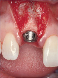
Fig 12 Buccal view of the implant with a beveled healing cap.
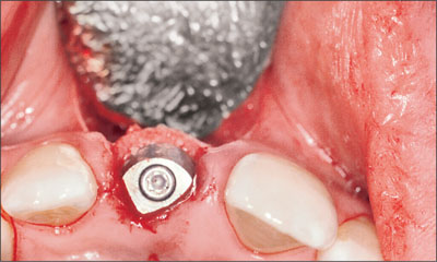
Fig 13 Occlusal view illustrating the addition of an autogenous bone graft into the horizontal defect dimension (HDD) along the buccal surface.
A semi-submerged flap closure was chosen to enhance the final positioning of the peri-implant soft tissues, and a periapical radiograph was taken immediately following surgery (Figs 14 to 16).
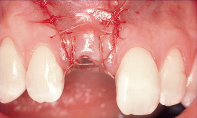
Fig 14 Buccal view of flap closure using a 5.0 Vicryl suture.
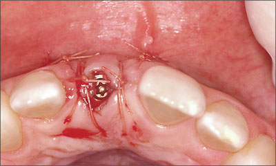
Fig 15 Occlusal view of flap closure using a semi-submerged closure technique.
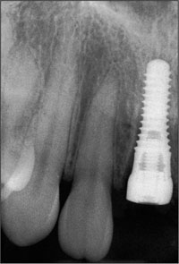
Fig 16 Periapical radiograph taken immediately following surgery.
Ten weeks following implant surgery, a small gingivectomy was performed to gain access to the beveled healing cap (Figs 17 and 18).
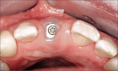
Fig 17 Occlusal view of the surgical site after 10 weeks of healing.
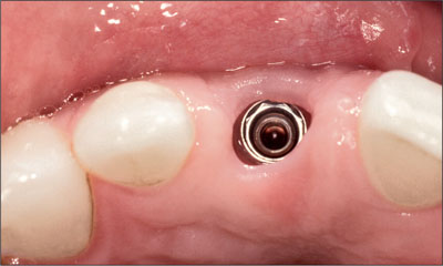
Fig 18 Removal of the healing cap following a minor gingivectomy procedure.
A synOcta post for temporary restorations was attached to the implant (Figs 19 and 20) and a self-curing acrylic resin provisional restoration was fabricated and marginated using a synOcta analog as described by Higginbottom and coworkers (2004) (Figs 21 and 22a-b).
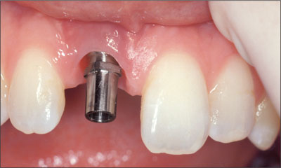
Fig 19 synOcta post for temporary restorations in place.
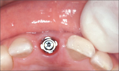
Fig 20 Occlusal view of the synOcta post for temporary restorations.
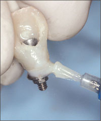
Fig 21 Margination of an acrylic screw-retained provisional restoration.
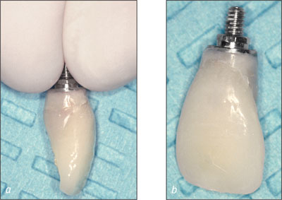
Figs 22a-b Emergence profile obtained using an acrylic provisional restoration.
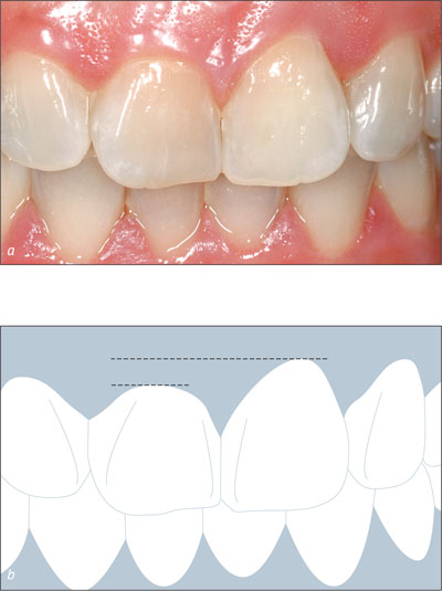
The peri-implant soft tissues were allowed to mature around the provisional restoration for four weeks prior to the final impression (Figs 23 to 25).
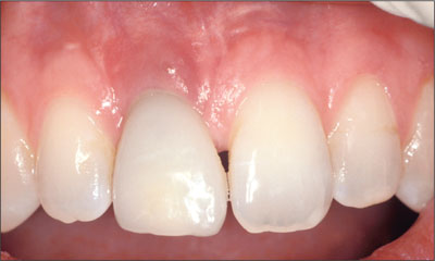
Fig 23 Placement of the provisional restoration. Note the initial closure of the midline diastema, resulting in a crown morphology that is too wide mesial-distally.
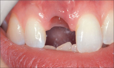
Fig 24 Buccal view of soft-tissue profile following tissue remodeling using the acrylic provisional restoration.
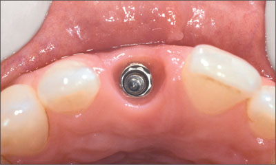
Fig 25 Occlusal view of the peri-implant sulcus following tissue remodeling using the acrylic provisional restoration.
At the time of the final impression, a synOcta screw-retained impression cap was attached to the implant and an open-tray impression technique was utilized (Figs 26 and 27).
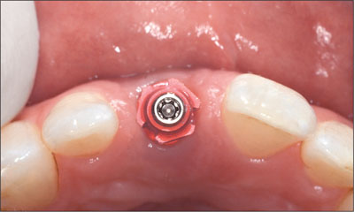
Fig 26 Occlusal view of synOcta screw-retained impression cap.
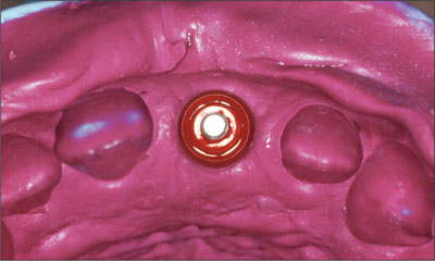
Fig 27 Final impression.
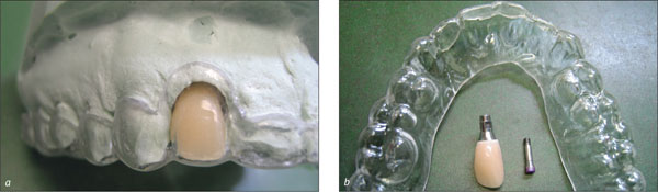
Following the connection of the analog to the impression cap, a master cast was fabricated to reproduce the implant location three-dimensionally. The master cast was then utilized to aid in the creation of a screw-retained cast-metal crown framework using a non-rotational synOcta gold coping on a synOcta 1.5 abutment (Fig 28).
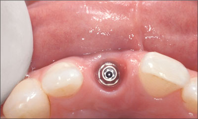
Fig 28 Occlusal view of mature peri-implant sulcular tissue with the synOcta 1.5 abutment.
After hand-tightening the abutment, the crown framework was attached to the implant with an SCS occlusal screw and a second definitive impression using a closed-tray technique was made to verify the peri-implant soft-tissue profiles (Figs 27 to 32).
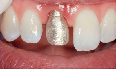
Fig 29 Buccal view of cast gold framework coping.
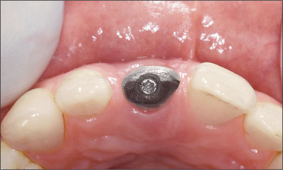
Fig 30 Occlusal view of cast gold framework coping.
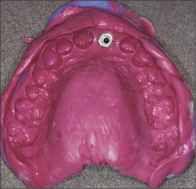
Fig 31 Impression of framework coping to verify soft-tissue profiles.
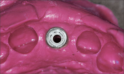
Fig 32 Close-up occlusal view of impression of framework coping to verify soft-tissue profiles.
The ceramic work was completed at the laboratory using this accurate master cast. The synOcta 1.5 abutment was torqued to 35 Ncm and the final crown was seated and checked for marginal fit, occlusal and interproximal contacts, and emergence profile (Fig 33).
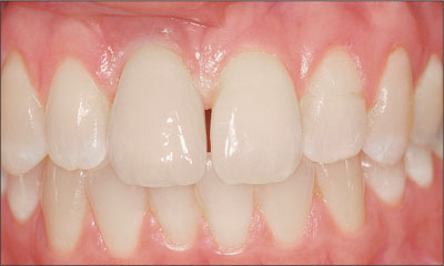
Fig 33 Buccal view of the final restoration, delivered 4 months after the initial surgery date.
Final glazing of the ceramics was then performed, and the SCS occlusal screw was tightened to 15 Ncm. The screw access was obturated with a cotton pellet and closed with a light-cured composite (Fig 34).
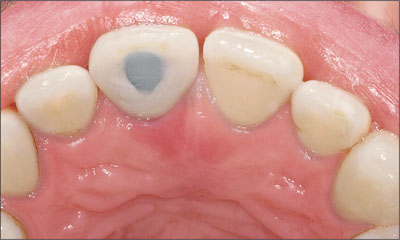
Fig 34 Occlusal view of the final screw-retained restoration.
A periapical radiograph was obtained to establish a baseline marginal bone level with maintenance visits scheduled every 6 months with the dental hygienist (Figs 35 and 36).
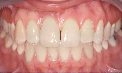
Fig 35 Extended buccal view of the final restoration delivered 4 months after the initial surgery date.
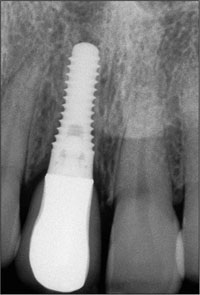
Fig 36 Periapical radiograph of the final restoration delivered 4 months following the initial surgery.
The one-year follow-up shows an excellent result clinically and radiographically with very stabile peri-implant soft tissues and optimal crestal bone heights (Figs 37a-b).
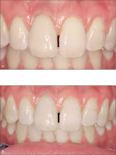
Figs 37a-b Buccal and extended buccal views of one-year post-restoration of the immediately placed Straumann Tapered Effect implant. Note the maturation of the peri-implant soft tissues.
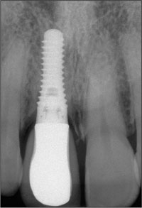
Fig 38 Periapical radiograph of tooth 11 one year following restoration. Note that there is no change in the interproximal bone levels.
Acknowledgments
Prosthetic Procedures
Dr. Richard Stuart – Private Practice, Indianapolis, Indiana, USA
Laboratory Procedures
Michael Hahn – Boca Raton, Florida, USA
4.2 Immediate Placement of an Implant in a Maxillary Left Central Incisor Site
S. Chen, A. J. Dickinson
A 33-year-old female patient presented with an upper left central incisor that required extraction after a failed endodontic therapy. The tooth had been traumatized when the patient was a teenager and had undergone several endodontic treatments, including two apicectomy procedures. The patient was in good health and did not smoke. Clinical examination showed that the patient had a high lip line. In full smile, the gingival margins of the upper teeth were visible to the first molars. The gingival margins of central incisors 11 and 21 were only just showing.
Examination of tooth 21 confirmed that the tooth was mobile and had hypererupted by 1 mm (Fig 1).
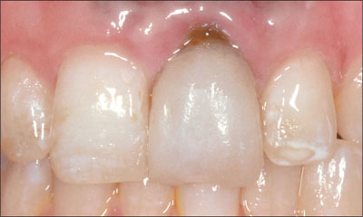
Fig 1 Facial view of the upper left central incisor showing recession and swelling of the facial gingival margin.
A probing depth of 8 mm was present on the mid-facial aspect of the tooth. The facial gingiva was swollen with 2 mm of recession. The papillae were intact on either side of the tooth. The patient’s tissue biotype was medium thick, with a broad band of keratinized mucosa. The central incisors were rectangular in shape; however, there was noticeable enamel hypoplasia affecting the upper anterior teeth. Significant scarring of the mucosa was observed as a result of endodontic surgical procedures. A diffuse amalgam tattoo was present.
Radiographically, the root of the tooth was short and a wide endodontic filling was present with an apical amalgam seal (Fig 2). A radiolucent periapical area was present. Adjacent teeth had intact proximal bone, and the distance from bone crest to contact point was approximately 5 mm both mesially and distally.
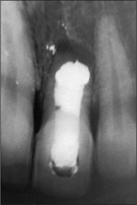
Fig 2 Periapical radiograph of tooth 21 showing the shortened root, apical amalgam seal, and a periapical area. There appeared to be sufficient bone height apically of the area of radiolucency.
An Esthetic Risk Assessment (ERA) was undertaken for the patient (Table 1). The patient’s lip line, high esthetic demands, and soft-tissue and bone defects resulted in a moderate to high esthetic risk for the replacement of tooth 21. In addition, the enamel hypoplasia increased the technical demands on achieving a good esthetic result.
| Esthetic Risk Factors | Low | Medium | High |
| Medical status | Healthy, cooperative patient with intact immune system | Reduced immune system | |
| Smoking habit | Non-smoker | Light smoker (<10 cig/d) | Heavy smoker (≥ 10 cig/d) |
| Patient’s esthetic expectations | Low | Medium | High |
| Lip line | Low | Medium | High |
| Tissue biotype | Low-scalloped, thick | Medium-scalloped, medium thick | High-scalloped, thin |
| Shape of tooth crowns | Rectangular | Triangular | |
| Infection at implant site | None | Chronic | Acute |
| Bone level at adjacent teeth | ≤ 5 mm to contact point | 5.5 to 6.5 mm to contact point | ≥ 7 mm to contact point |
| Restorative status of neighboring teeth | Virgin | Restored | |
| Width of edentulous span | 1 tooth (≥ 7 mm) | 1 tooth (<7 mm) | 2 teeth or more |
| Soft-tissue anatomy | Intact soft tissue | Soft-tissue defects | |
| Bone anatomy of alveolar crest | Alveolar crest without bone deficiency | Horizontal bone deficiency | Vertical bone deficiency |
Following discussions with the patient, a treatment plan was established that included the extraction of tooth 21 and the placement of an implant immediately into the socket (Type 1). It was anticipated that both hard- and soft-tissue augmentation would be required. Due to the amalgam tattoo and the risk of it showing in the patient’s smile, only limited advancement of the facial flap was proposed. Thus, a semi-submerged healing protocol was chosen. The degree of apical bone loss increased the risk of not achieving ideal initial stability. It was further anticipated that the residual defect would have at least two intact bone walls that would permit simultaneous bone augmentation at the time of implant placement. However, the actual situation would only be confirmed at the time of surgery and hence a contingency plan to stage bone augmentation and implant placement was discussed with the patient. Although the anatomic risk was low, the risk of esthetic complications was high. Therefore, the proposed treatment to place an immediate implant (Type 1) was considered to be a complex procedure according to the SAC classification.
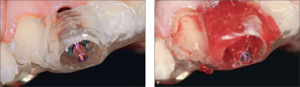
After administration of local anesthesia, a flap was raised on the facial aspect to expose the root and surrounding bone. The flap was designed such that the mesial and distal papillae were not involved (Fig 3). Intrasulcular incisions were made on the mesial, distal and palatal surfaces. After careful extraction of the tooth, the loss of the facial bone wall was evident (Fig 4).
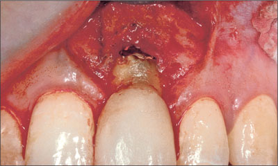
Fig 3 Facial view of site 21 following flap reflection. The flap was designed not to involve the papillae.
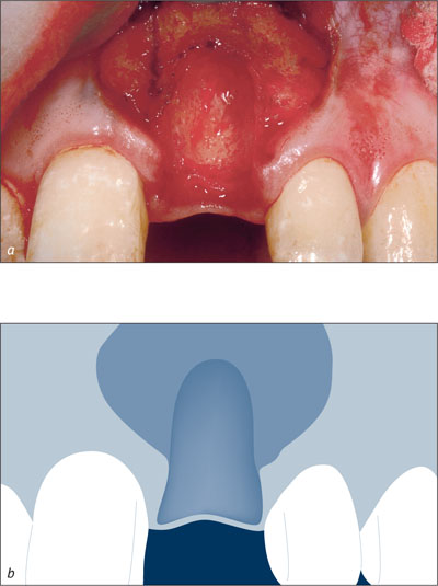
Figs 4a-b Facial view of site 21 after tooth extraction reveals the loss of the facial bone wall.
The dehiscence defect was wide at the crestal region of the socket. The socket was debrided with hand instruments to remove soft-tissue remnants. A Straumann Standard Plus implant (endosteal diameter 4.1 mm, length 12 mm, Regular Neck prosthetic platform 4.8 mm) with TPS surface was inserted after the preparation of the site. Care was taken to ensure that the implant shoulder was positioned within the remaining socket walls (Fig 5).
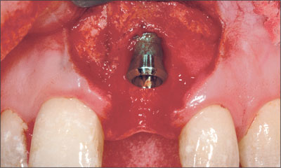
Fig 5 Site 21 after implant placement with the implant shoulder positioned within the remaining socket walls
The resultant peri-implant defect had two bone walls, which permitted simultaneous bone augmentation to be performed. Deproteinized bovine bone mineral (Bio-Oss, Geistlich) was grafted to the site to fill the defect to the level of the implant shoulder (Fig 6). A resorbable collagen membrane (Bio-Gide, Geistlich) was trimmed and adapted over the bone graft and surrounding bone (Fig 7). A connective-tissue graft was then harvested from the palate and placed over the membrane close to the neck of the implant (Fig 8). The connective-tissue graft was stabilized by a sling suture that was secured to the palatal mucosa. The periosteum at the base of the flap was released and the flap coronally advanced to allow for a semi-submerged healing of the tissue around the implant (Fig 9). The patient was instructed to use a chlorhexidine rinse (0.2%) twice daily for two weeks and not to brush the surgical area. Systemic antibiotics were prescribed (amoxicillin 500 mg twice daily for 7 days).After two weeks, the patient commenced mechanical cleaning of the implant and adjacent teeth. Healing progressed uneventfully, and after six months the implant had integrated and the peri-implant mucosa was healthy (Fig 10).
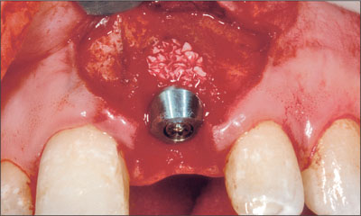
Fig 6 Implant site after grafting with deproteinized bovine bone mineral.
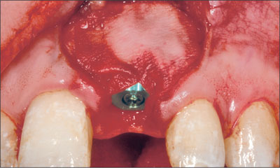
Fig 7 Implant site after adaptation of a resorbable collagen membrane.
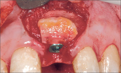
Fig 8 A connective-tissue graft was positioned over the graft and membrane and secured around the healing cap with a sling suture.
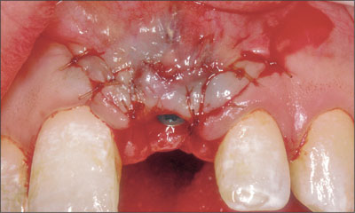
Fig 9 Implant site after suturing. The flap was advanced to allow semi-submerged healing.
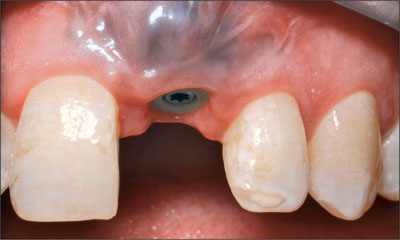
Fig 10 After 6 months of healing, the peri-implant tissue was healthy.
A screw-retained provisional crown was attached to the implant. Several adjustments were made to the contour of the provisional crown in order to achieve symmetry of form with the adjacent central incisor. The implant was then restored with a screw-retained metal-ceramic crown. The patient returned for a review 12 months after surgery (Fig 11). Annual recalls were scheduled for the maintenance and monitoring of the implant. Peri-implant tissue health and stable bone conditions were noted at the 4-year recall (Figs 12 to 14).
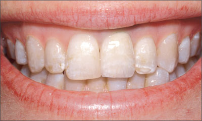
Fig 11 Extraoral facial view of the patient’s smile showing the implant 12 months after surgery. The amalgam tattoo was not visible when the patient smiled.
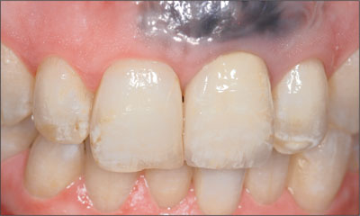
Fig 12 Intraoral facial view of the implant 4 years after surgery.
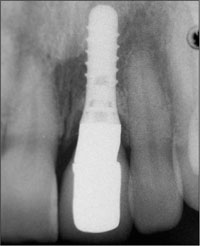
Fig 13 Periapical radiograph of the implant 4 years after surgery.
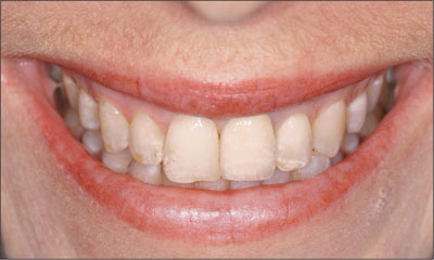
Fig 14 Facial view of the patient when smiling 4 years after surgery.
At the 8-year recall, all soft- and hard-tissue parameters were stable, and an ideal esthetic result was maintained (Figs 15 and 16).
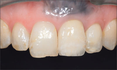
Fig 15 Facial view of the implant 8 years after surgery. Excellent mucosal health and stability has been achieved over this period.
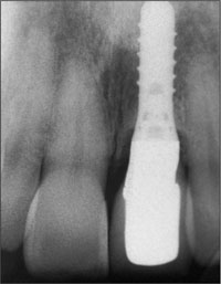
Fig 16 Radiograph of the implant 8 years after surgery. The marginal bone has remained stable over this time.
Acknowledgments
Laboratory Procedures
John Lucas – Melbourne, Australia
4.3 Immediate Flapless Placement of an Implant in a Maxillary Left Central Incisor Site
S. Chen
A 29-year-old female patient presented for treatment to replace the upper left central incisor tooth with an implant-supported restoration. The tooth had been intermittently symptomatic for the previous 12 months. The tooth had originally suffered trauma about 15 years previously. Several endodontic treatments had been performed, including an apicectomy procedure to retain the tooth.
The patient was healthy and a non-smoker. She had reasonable expectations in regard to esthetic outcomes and the risk of marginal tissue recession following treatment. At medium smile, the gingival margins of the upper teeth were visible, with a display of 3 to 4 mm of the gingival margins (Fig 1). Gingival recession of tooth 21 and a discrepancy in the gingival levels between teeth 11 and 21 was observable during normal speech and smile.
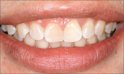
Fig 1 At medium smile, the patient displayed the gingival margins of the upper anterior teeth. The discrepancy in gingival height between teeth 11 and 21 was visible.
Clinical examination showed that tooth 21 exhibited normal probing depth and a healthy gingiva (Fig 2).
Figs 2a-b Intraoral facial view of the upper anterior teeth. The gingival margin on tooth 21 had receded. Tooth 11 had a short clinical crown and was “square” in shape.
The gingiva on tooth 21 had receded by 2 mm compared to tooth 11. Scarring of the mucosa from previous apical surgery was noted. The papillae were intact on either side of the tooth. The patient’s tissue biotype was of medium thickness with a broad band of keratinized mucosa. Tooth 11 was square in shape. Teeth adjacent to the site were unrestored and the remaining dentition was healthy.
Radiographically, the root of the tooth was short, and a large periapical area was seen (Fig 3).
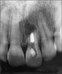
Fig 3 Preoperative periapical radiograph of tooth 21. The tooth had been endodontically treated, and an apicectomy had been performed.
Adjacent teeth showed normal proximal bone levels and the distance from bone crest to contact point was approximately 4 mm on the mesial and distal aspects of the tooth.
An Esthetic Risk Assessment (ERA) was undertaken for the patient (Table 1).The patient’s high lip line, pre-existing gingival recession, and bone defects resulted in a moderate to high esthetic risk for the replacement of tooth 21. The treatment plan was to extract the tooth and assess the socket. Depending upon the condition of the facial bone, a decision would then be made as to whether an implant could be placed, or whether implant placement should be deferred until initial healing had occurred. The plan also called for surgical crown-lengthening of tooth 11 to provide a tooth with a more pleasing width-to-height ratio. Lengthening of this tooth in a gingival direction would also compensate for the pre-existing recession on tooth 21.
| Esthetic Risk Factors | Low | Medium | High |
| Medical status | Healthy, cooperative patient with intact immune system | Reduced immune system | |
| Smoking habit | Non-smoker | Light smoker (<10 cig/d) | Heavy smoker (≥ 10 cig/d) |
| Patient’s esthetic expectations | Low | Medium | High |
| Lip line | Low | Medium | High |
| Tissue biotype | Low-scalloped, thick | Medium-scalloped, medium thick | High-scalloped, thin |
| Shape of tooth crowns | Square | Triangular | |
| Infection at implant site | None | Chronic | Acute |
| Bone level at adjacent teeth | ≤ 5 mm to contact point | 5.5 to 6.5 mm to contact point | ≥ 7 mm to contact point |
| Restorative status of neighboring teeth | Virgin | Restored | |
| Width of edentulous span | 1 tooth (≥ 7 mm) | 1 tooth (<7 mm) | 2 teeth or more |
| Soft-tissue anatomy | Intact soft tissue | Soft-tissue defects | |
| Bone anatomy of alveolar crest | Alveolar crest without bone deficiency | Horizontal bone deficiency | Vertical bone deficiency |
It was anticipated that implant placement at the time of extraction (Type 1) could involve the need for adjunctive hard- and soft-tissue grafting procedures. Although the anatomic risk for this procedure would be low, the risk of esthetic complications was significant. The “immediate implant” approach would have a level of difficulty of at least advanced to complex according to the SAC classification. An alternative approach would be to extract the tooth and to allow initial soft-tissue healing to occur. The implant could then be placed as an early procedure (Type 2). With this approach, the increased volume of soft tissue would facilitate flap management in order to achieve a good soft tissue esthetic outcome. Adjunctive hard and/or soft tissue grafting would still be required. This approach would have a degree of difficulty of at least advanced according to the SAC classification. The patient was fully informed of these possible treatment options and consented to treatment.
After anesthetizing tooth 21, a sulcular incision was made circumferentially. Using fine luxators and forceps, the tooth was carefully extracted with as little trauma to the bone and soft tissue as possible (Fig 4).
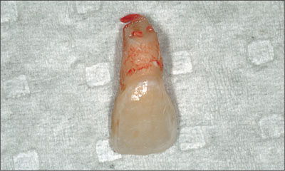
Fig 4 View of the tooth following extraction.
The socket was thoroughly debrided with hand instruments to remove apical pathological tissue and soft-tissue tags. Inspection of the socket revealed an almost intact socket, except for an apical fenestration of the facial bone wall. The fenestration was 4 to 5 mm in diameter and was located adjacent to the periapical area seen on the pretreatment radiograph. The facial bone wall appeared to have reasonable thickness at the cervical region of the tooth.
At this juncture, a decision was made to place an implant without the elevation of surgical flaps. The external facial and palatal bone walls were sounded through the mucosa with a hypodermic needle to provide a tactile impression of the ridge dimensions. A concavity of the facial bone wall was detected immediately apically of the fenestration defect. The osteotomy was then prepared into the apical half of the palatal socket wall. Care was taken to place the implant well away from the facial fenestration and concavity of the ridge. The palatal marginal bone was prepared to allow the implant to be placed with the shoulder in a palatal position in the socket, and with screw access on the palatal side of the incisal edge of the final restoration. A Straumann Standard Plus implant (endosteal diameter 4.1 mm, length 10 mm, Regular Neck prosthetic platform 4.8 mm) with SLA surface was placed into the osteotomy (Fig 5).
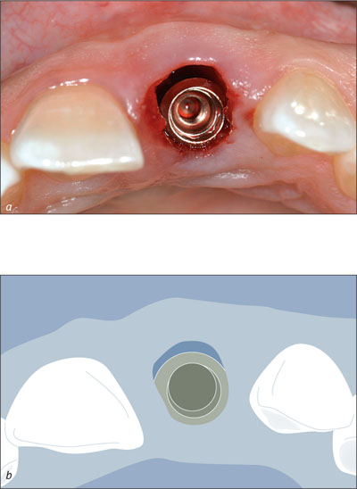
Figs 5a-b Occlusal view of site 21 after the installation of the implant. The implant was placed without flap elevation. Note the palatal position of the implant shoulder. An apical fenestration was present, but the marginal bone was intact at the crest.
The implant shoulder was placed 2 mm beneath the level of the mid-facial gingival margin (Fig 6).
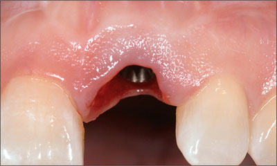
Fig 6 Facial view of site 21 following the placement of the implant.
A 2-mm healing cap was attached, verifying the ideal location of the implant shoulder in relation to the marginal soft tissue (Fig 7). The clinical crown of the adjacent tooth 11 was lengthened by 2 mm by resection of the marginal gingiva. Bone-sounding indicated a supracrestal zone of gingiva 5 mm in size. Thus, the tooth could be crown-lengthened without the need for flap elevation and osseous surgery.
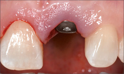
Fig 7 A 2-mm healing cap was attached to the implant. The adjacent tooth 11 was crown-lengthened by 2 mm.
No sutures were used. A temporary partial denture was trimmed to avoid contact with the soft tissue and implant at site 21.
The patient was instructed to apply a 2% chlorhexidine gel to the healing cap and to refrain from mechanical cleaning for 1 week. After 1 week, the patient was asked to gently clean the top of the implant with a soft toothbrush.
The patient returned for a postoperative review 2 weeks following surgery. The mucosa was fully healed and healthy (Figs 8 and 9).
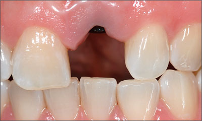
Fig 8 After 2 weeks of healing, the mucosal condition around the implant in site 21 and the adjacent natural tooth 11 was excellent.
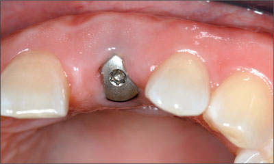
Fig 9 Occlusal view of site 21, 2 weeks following surgical placement of the implant. Note that slight flattening of the mid-facial mucosa had occurred.
After 8 weeks, the patient was referred to her dentist for final restoration. A radiograph at this time showed ideal bone conditions (Figs 10 and 11).
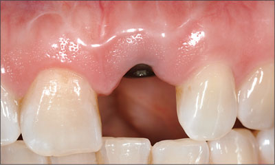
Fig 10 Intraoral facial view of site 21 after 8 weeks of healing. The soft tissues were fully healed.
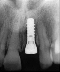
Fig 11 Periapical radiograph of the implant 8 weeks after implant placement.
The patient returned for a review 5 months after surgery. The implant had been restored with a screw-retained metal-ceramic crown (Fig 12).The soft tissue levels were symmetrical and the papillae were well-formed and completely filled the embrasure areas. A harmonious and esthetic implant restoration was achieved within the patient’s anterior dentition (Fig 13). A radiographic control was not obtained at this time because the patient was pregnant.
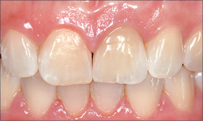
Fig 12 Intraoral facial view of the implant following restoration with a screw-retained metal-ceramic crown.
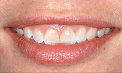
Fig 13 Extraoral facial view of the patient’s anterior dentition with a medium smile. Good soft tissue symmetry was achieved with the adjacent tooth, and the implant restoration blended well within the dentition.
Three years after surgery, the marginal mucosa and bone conditions were stable at the implant site (Figs 14 and 15). A discrepancy in the level of the incisal edges between the implant in site 21 and the adjacent tooth 11 was observed.
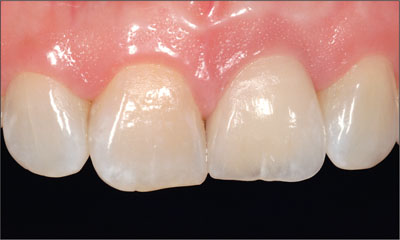
Fig 14 Intraoral facial view of site 21 at 3 years after initial surgery. The marginal mucosa was healthy and dimensionally stable. Note the 1-mm discrepancy in the incisal edge levels between natural tooth 11 and implant site 21.
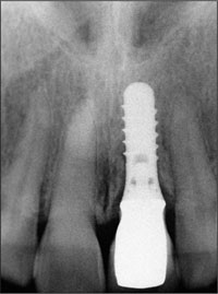
Fig 15 Periapical radiograph of the implant three years after initial surgery, demonstrating stable marginal bone conditions.
The patient was seen for a review 5 years after implant placement (Figs 16 to 18). The peri-implant tissues were healthy with stable supporting bone.
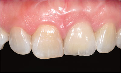
Fig 16 Intraoral facial view of the implant 5 years after implant placement.
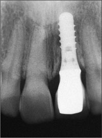
Fig 17 Radiographic follow-up 5 years after implant placement .
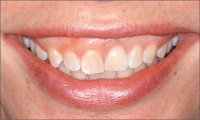
Fig 18 Extraoral facial view of the patient when smiling 5 years after implant placement.
Of note was the discrepancy in the incisal edge levels between the implant restoration and the adjacent tooth 11, most likely a result of ongoing dentofacial growth.
Acknowledgments
Prosthetic Procedures
Dr. Simon Wylie – Melbourne, Australia
4.4 Immediate Placement of an Implant in a Mandibular First Molar Site
R. Cornelini
A 32-year-old male patient in good general health, a non-smoker, presented with a very large carious lesion in the mandibular left first molar (tooth 36).
The probing depth around the molar was between 1 and 2 mm. This tooth was considered hopeless for three reasons:
-
The carious lesion at the level of the root furcation that could lead to tooth fracture.
-
The tooth was extruded because of the loss of almost the entire crown. As a result, the crown-to-root ratio was unfavorable.
-
Maintaining the tooth by means of crown lengthening would lead to furcation exposure.
Based on these considerations, tooth extraction and immediate implant placement (Type 1) was planned in agreement with the patient. Immediate placement offers an obvious advantage to the patient, as the time interval between tooth extraction and the placement of the final restoration is minimized. Additionally, patient morbidity is reduced.
An indispensable condition for immediate implant placement (Type 1) is the presence of basal bone for primary stabilization, which is necessary to achieve osseointegration. This may pose serious problems at the level of the mandibular first molar for the presence of the alveolar inferior nerve. However, in this case, due to the extrusion of the roots, a sufficient volume of basal bone was present in the vertical dimension.
After a sulcular incision on the buccal aspect of tooth 36, followed by two releasing vertical incisions, a full-thickness flap was raised.
The two roots were separated by a carbide bur to allow the extraction of the tooth and to prevent root fracture. After root separation, the interseptal bone was removed to facilitate the extraction and to make the preparation of the implant site easier (the presence of the interseptal bone can deflect the bur mesially or distally during the osteotomy). For immediate implant placement (Type 1), it is very important to maintain the integrity of the socket to avoid guided bone regeneration (GBR) procedures.
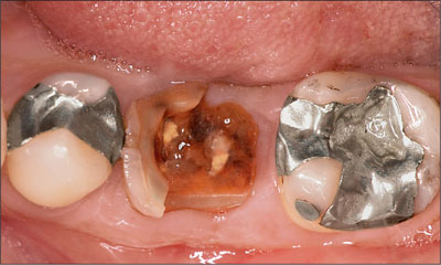
Fig 1 Occlusal view at baseline, showing a large carious lesion in the mandibular left first molar.
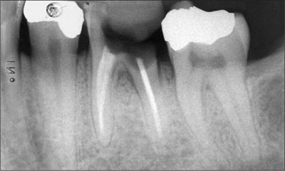
Fig 2 X-ray at baseline. The carious lesion involves the furcation.
Subsequently, with the help of periotomes, the two roots were removed by applying adequate force on the mesial (for the mesial root) and on the distal (for the distal root) aspects of the socket. A surgical curette was used to remove granulation tissues from the socket.
After the extraction, a 0.12% chlorhexidine digluconate solution was used for topical disinfection.
After the preparation of the implant site, a Straumann Tapered Effect implant (endosteal diameter 4.8 mm, length 12 mm, Wide Neck prosthetic platform 6.5 mm) was placed.
The rationale for using a wide-diameter implant is consistent with the conclusion of many authors who have demonstrated that the reduction of the gap between the bone and the implant surface may improve osseointegration. The implant was positioned in perfect central position with a bone-to-implant gap that ranged between 1 and 3 mm. For situations in which the gap is over 2 mm, the use of a membrane to protect the bone defect has been advocated by many authors (Brunel and coworkers, 1998; Akimoto and coworkers, 1999; Stentz and coworkers, 1997).
The rationale underlying the use of a barrier membrane is that they have a space-maintaining effect around the implant to facilitate the formation, retention, and stabilization of the blood clot. Additionally, the membrane prevents the connective tissue from collapsing into the peri-implant defect and thus increases the likelihood of bone regeneration.
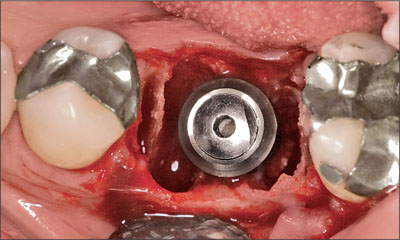
Fig 3 Tapered Effect implant in situ after immediate placement (Type 1). The implant is centrally positioned.
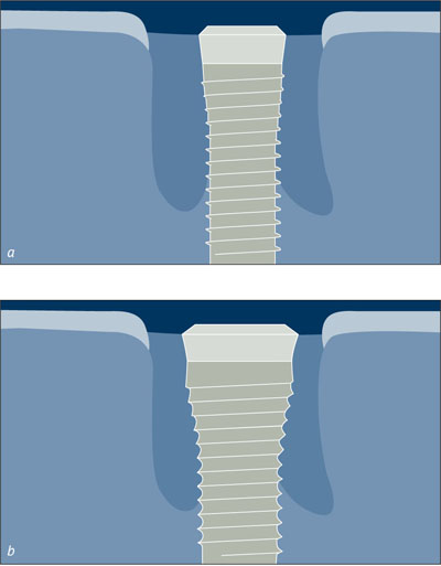
Figs 4a-b A large implant diameter reduces the gap between the bone and the implant and improves osseointegration.

Fig 5 Radiograph at baseline after implant placement. The implant shoulder is level with the most coronal part of the bone crest.
It is a recognized problem that membranes may collapse into the defect during healing because of degradation and the loss of stiffness. This can in turn reduce the amount of potential bone gain during healing. In this particular case, no fill material was needed, as this was a four-wall defect without any bone dehiscence. Thus, only a resorbable membrane (Bio-Gide, Geistlich) was placed over the bone defect.
The periosteum was incised at the apical level of the buccal flap to allow for flap mobilization in the coronal direction. Before suturing, the epithelium present on the buccal and lingual gingival margins was removed. Finally, the flap was displaced lingually to create contact between the buccal and lingual gingival margins. Particular care was taken to avoid any tension in the flap that might lead to soft-tissue dehiscence. Primary wound closure was obtained by horizontal mattress sutures and interrupted sutures.
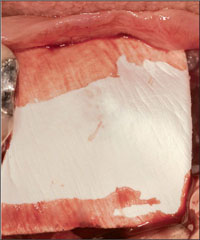
Fig 6 Resorbable membrane in place over the bone defect.
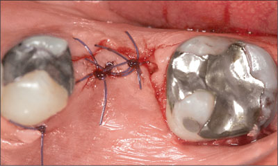
Fig 7 After a periosteal incision at the apical level of the buccal flap, the flap was mobilized in the coronal direction and sutured.
There are two different approaches to immediate implant placement (Type 1): submerged and non-submerged. In the first case, the implant is covered by the flap, and a second entry is necessary to expose the head of the implant for subsequent procedures. In a non-submerged approach, a healing cap is fixed on the implant, and the flap is sutured around it to protect the residual bone defect.
In this clinical case, a submerged approach was used because of the difficulty in moving the lingual flap coronally to allow for primary closure to protect the residual bone defect and to prevent an early exposure of the membrane. Antibiotics (V-penicillin, 1g twice daily) were prescribed for 8 days post-surgery. In addition, the patient was instructed to rinse twice daily with a 0.12% aqueous chlorhexidine solution until the removal of the sutures (at 2 weeks). Chlorhexidine spray was used for an additional 2 weeks. Instruction in adequate mechanical cleaning of the implant site was given at the 4-week follow-up visit. Recalls for maintenance care were scheduled every 4 weeks until the prosthetic restoration was placed. Perfect healing of the soft tissues was observed 3 months later.
After 4 months, the second entry was performed. An incision in the middle of the crest was performed, and a full thickness flap, both on the buccal and the lingual side, was raised.
No residual bone defects around the implant were detected. A vertical bone resorption of 1.5 mm was revealed around the smooth implant neck portion. A horizontal bone resorption of 2 mm was revealed on both the buccal and lingual aspect.
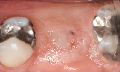
Fig 8 Soft-tissue healing after 4 months.
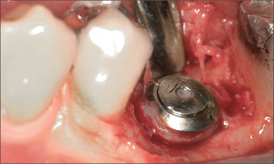
Fig 9 Bone healing after 4 months.
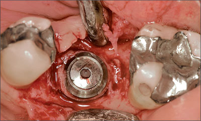
Fig 10 Occlusal view. Complete closure of the bone defect.
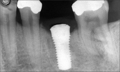
Fig 11 Bone healing after 4 months.
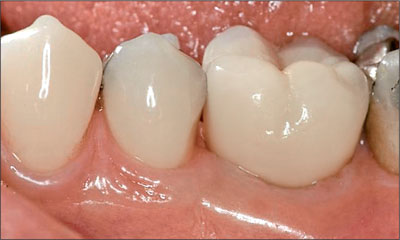
Fig 12 Clinical 12-month follow-up.
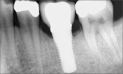
Fig 13 Radiograph taken 12 months after the insertion of the final restoration.
A healing cap was positioned and the flaps were sutured. One month after the second surgical entry, the impression was made. The final restoration was inserted after 3 months.
Acknowledgments
Laboratory Procedures
Smile Art – Santarcangelo di Romagna, Italy
4.5 Immediate Flapless Placement of an Implant in a Maxillary Right Second Premolar Site
M. Roccuzzo
This 22-year-old female patient, a light smoker, came to the office in January 2007 because of a fracture of the endodontically treated tooth 15. The fracture had been caused by severe decay.
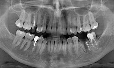
Fig 1 Orthopantomograph taken during the patient’s first visit in January 2007.
The periapical radiograph revealed the full extent of the loss of tooth substance.
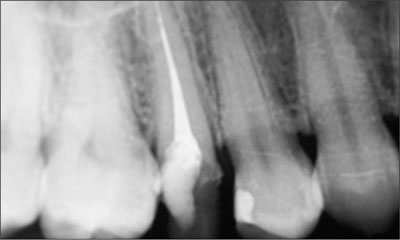
Fig 2 Periapical radiograph taken in January 2007.
The amount of healthy dentine was not sufficient for a stump preparation for a conventional crown due to the extent of decay and due to the fact that the fracture line extended below the bone level (Fig 3).
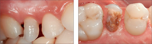
Figs 3a-b Fractured tooth 15, buccal and occlusal view.
Therefore, the patient was offered the following treatment options:
-
Extraction of tooth 15 and gap closure with a conventional tooth-supported bridge.
-
Orthodontic extrusion of tooth 15 and subsequent cementation of a conventional single crown.
-
Extraction of tooth 15 and replacement by a dental implant.
| Esthetic Risk Factors | Low | Medium | High |
| Medical status | Healthy, cooperative patient with intact immune system | Reduced immune system | |
| Smoking habit | Non-smoker | Light smoker (<10 cig/d) | Heavy smoker (≥ 10 cig/d) |
| Patient’s esthetic expectations | Low | Medium | High |
| Lip line | Low | Medium | High |
| Tissue biotype | Low-scalloped, thick | Medium-scalloped, medium thick | High-scalloped, thin |
| Shape of tooth crowns | Rectangular | Triangular | |
| Infection at implant site | None | Chronic | Acute |
| Bone level at adjacent teeth | ≤ 5 mm to contact point | 5.5 to 6.5 mm to contact point | ≥ 7 mm to contact point |
| Restorative status of neighboring teeth | Virgin | Restored | |
| Width of edentulous span | 1 tooth (≥ 7 mm) | 1 tooth (<7 mm) | 2 teeth or more |
| Soft-tissue anatomy | Intact soft tissue | Soft-tissue defects | |
| Bone anatomy of alveolar crest | Alveolar crest without bone deficiency | Horizontal bone deficiency | Vertical bone deficiency |
The patient was highly concerned about her esthetics and asked for a “fast” treatment; she had very high expectations with regard to the esthetics of the treatment outcome. It was especially important to her that a “nice smile” was restored as quickly as possible. Therefore, a decision was made together with her to extract the tooth and place an implant following an immediate placement protocol (Type 1).
Since the tooth remnant, due to its shape and position, maintained a marginally acceptable “nice smile” (Fig 3a), it was left in place for 2 weeks, and extraction and implant placement were scheduled.
In this patient the soft tissues were healthy with no bleeding on probing, good thickness, and the absence of pockets and recessions (Fig 4a). Also, considering the dimensions of the future implantation site, immediate implant placement (Type 1) was considered to be the treatment of choice (Fig 4b).
Figs 4a-b The status of the future implantation site and its dimensions were checked.
The patient was informed that immediate implant placement (Type 1) would be aimed for, but she was also told that an immediate restoration could not be guaranteed. The patient gave her informed consent.
The tooth was carefully extracted in a minimally invasive mode, using periotomes and taking care not to damage the soft tissues or bony socket walls (Fig 5).
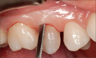
Fig 5 Minimally invasive extraction with periotomes.
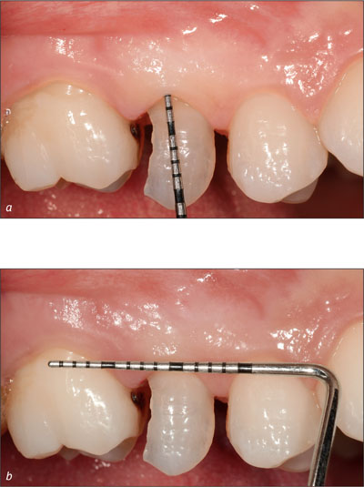
After extraction, the root remnant was checked for completeness and measured to determine the exact size of the extraction socket (Figs 6 and 7a-b).
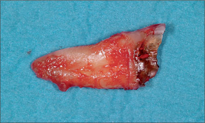
Fig 6 Root remnant.
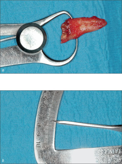
Figs 7a-b The widest orofacial dimension of the root was 7.5 mm.
Based on the dimensions of the root, it was decided to place a Straumann Tapered Effect (TE) implant (endosteal diameter 4.1 mm, length 12 mm, Regular Neck prosthetic platform 4.8 mm).
Due to the measurements made, it was evident that a gap of approximately 3 mm would remain between the implant and the socket. Before implant placement, the socket was carefully checked, and it was concluded that it would be possible to achieve good primary implant stability.
Before the actual implant placement, the socket was carefully checked for any bony defects and the bony walls turned out to be intact (Fig 8).
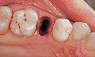
Fig 8 Extraction site after the minimally invasive extraction of the tooth remnant.
Before the placement of the implant, it was confirmed that the teeth adjacent to the extraction site were free of pathologies. A carious lesion was detected on the mesial aspect of tooth 16 (Fig 9), and it was agreed that it would be treated by the patient’s referring dentist before the placement of the final implant-borne crown.
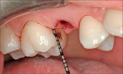
Fig 9 The teeth adjacent to the extraction site were checked for periodontal pockets.
The implant bed was prepared (Fig 10) and the implant was placed in an ideal three-dimensional position (Figs 11 and 12) (Buser and coworkers, 2007).
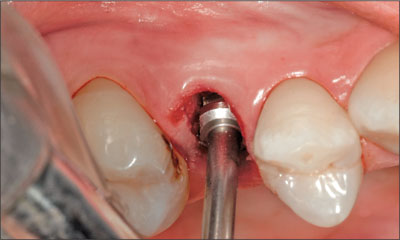
Fig 10 Final step of implant preparation with the profile drill.
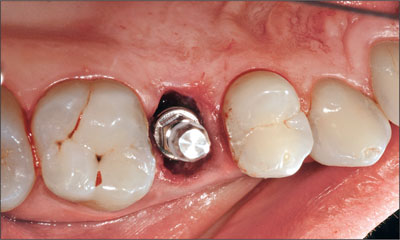
Fig 11 Implant in place, with the transfer still attached.
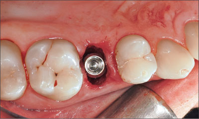
Fig 12 The buccal and the palatal gap between the implant and the bony alveolar walls needed to be filled with a bone substitute material.
The implant, TE SLA 12 mm ∅ 4.1 mm RN, was manually inserted in a self-tapping fashion, and primary stability was achieved. When placing implants in extraction sockets, special care needs to be taken not to place the implant shoulder too far apically and not to place the implant too close to the buccal socket wall in order to prevent the appearance of the metal margin after the buccal bone wall resorption.
A decision was made to fill the gaps between the implant and the bony socket walls with a bone substitute material (Bio-Oss Collagen Geistlich Pharma, Wolhusen, Switzerland) in order to support the soft tissues and to achieve a nice convex contour of the labial aspect of the alveolar arch (Fig 14). To prevent bone substitute particles from being trapped in the implant, it was carefully covered with a healing cap (Fig 13).
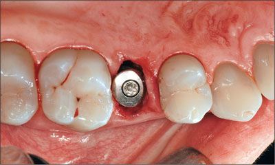
Fig 13 Implant with healing cap attached.
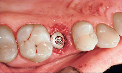
Fig 14 Implant site after the application of the bone substitute material and before the removal of the healing cap.
As one goal of the augmentation procedure is to support the buccal bony contour as well as the soft tissues at the implantation site, i.e. to keep the soft-tissue profile as convex as possible, it is important that the augmentation material does not resorb too fast.
Immediately after the bone augmentation and the removal of the healing cap, a 4.0 mm-high Regular Neck solid abutment was placed in the implant for the attachment of the provisional crown and hand-tightened (Fig 15).
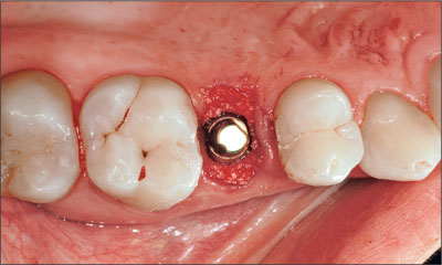
Fig 15 Regular Neck solid abutment in place.
After the attachment of the abutment, the augmented implantation site was covered with Atrisorb (Atrix Laboratories), a flowable polylactide polymer, in order to prevent the bone substitute particles from dislocating. After application, the material barrier was misted with a fine spray of sterile saline solution for solidification (Fig 16).
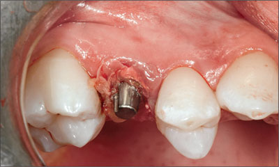
Fig 16 Augmented implantation site covered with a flowable polylactide polymer.
The provisional cement-retained crown was then placed on the abutment and occlusion was meticulously checked in order to remove any centric and eccentric occlusal contacts (Fig 17).
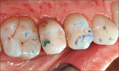
Fig 17 Freshly inserted provisional crown, before the removal of an occlusal contact on the distal aspect of the occlusal surface.
The patient was instructed to follow a soft diet for 3 weeks, to brush very carefully and to rinse with 0.2% chlorhexidine digluconate solution for 1 minute 3 times a day for the same period. She was scheduled for a control visit 6 days after implant placement.
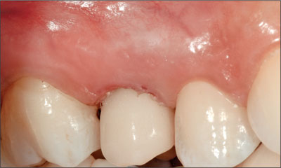
Fig 18 Implant-supported provisional crown in site 15 at 30 minutes after surgery.
At this control inspection, the peri-implant soft tissues presented healthy (Fig 19), and no adverse effects were reported by the patient.
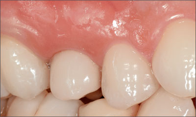
Fig 19 Implant-supported provisional crown 6 days after implant placement. Occlusion was checked once more to make sure that occlusal contacts were absent.
The abutment was tightened at 35 Ncm with a ratchet 2 months later (Fig 20), and it was decided to take the impression for fabrication of the final crown.
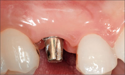
Fig 20 Abutment after removal of the provisional crown and after tightening to 35 Ncm. At the time of its attachment to the implant, it had been hand-tightened to about 15 Ncm.
During that same visit, a periapical radiograph was taken and the proper implant position, osseointegration, and stable peri-implant bone levels could be confirmed (Fig 21).
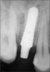
Fig 21 Control radiograph taken 2 months after implant placement.
Subsequently, the impression was taken and a cast was poured in the dental laboratory (Fig 22).
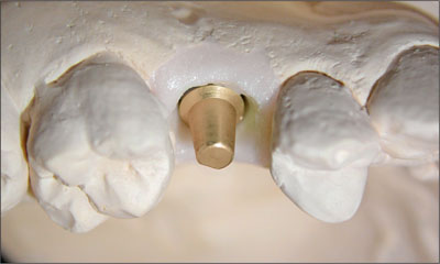
Fig 22 The solid abutment on the master cast in a close-up view with a mucosa mask.
Before the cementation of the final metal-ceramic crown (Fig 24), the peri-implant soft tissues were checked with a probe, and probing depths turned out to be physiological (Fig 23). Meanwhile, the carious lesion on tooth 16 had been treated by the patient’s referring dentist.
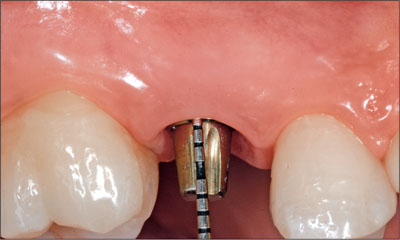
Fig 23 At the time of the cementation of the final crown, the soft tissues and the peri-implant bone presented healthy and stable. Probing depths were within the physiological range.
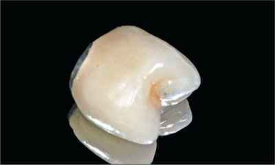
Fig 24 Final metal-ceramic crown before cementation.
The patient was scheduled for a control visit about 1 week after the cementation of the final restoration, at which time the implantation site presented healthy and inflammation-free and probing depths were physiological (Fig 25).
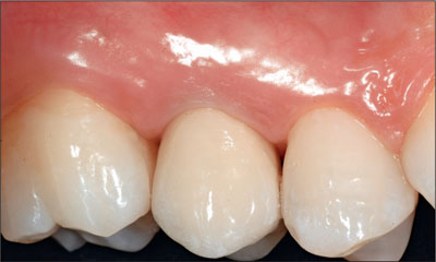
Fig 25 Clinical situation about 6 days after the integration of the final restoration.
A couple of weeks later, the implantation site presented healthy and the esthetics of the treatment outcome were stable and very pleasing.
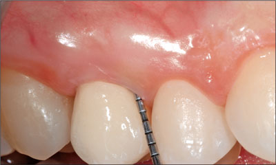
Fig 26 Clinical situation 2 weeks after the cementation of the final crown.
The periapical radiograph taken during that same visit confirmed stable peri-implant bone levels (Fig 27).
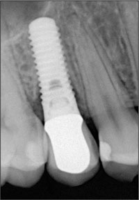
Fig 27 Radiograph taken in December 2007.
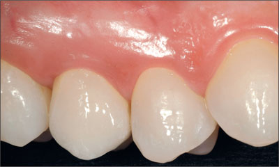
Fig 28 Clinical 1-year follow-up, close-up view.
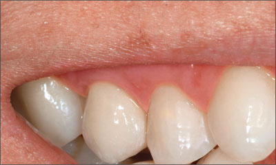
Fig 29 Clinical 1-year follow-up, smile line.
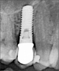
Fig 30 Radiological 1-year follow-up (digital radiograph).
Acknowledgments
The help of Dr. Luca Bonino, Ms. Michela Bui, and Ms. Silvia Lissona has been greatly appreciated.
Laboratory Procedures
Francesco Cataldi – Master Dental Technician, Torino, Italy
4.6 Immediate Flapless Placement of an Implant in a Maxillary Right Lateral Incisor Site
R. Nieberler
This 43-year-old male patient, a non-smoker, came to our practice because of a fracture of tooth 12 caused by a bicycle accident (Fig 1).
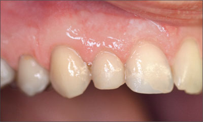
Fig 1 Initial clinical situation at the patient’s first visit to the dental practice.
Due to the combined para- and infrabony crown and root fracture (Fig 2),tooth extraction, and subsequent implant placement were suggested to the patient as the therapy of choice.
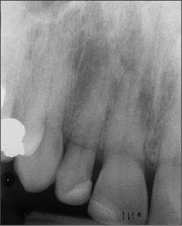
Fig 2 Initial periapical radiograph taken during the patient’s first visit. The combined crown and root fracture of tooth 12 is clearly visible.
The patient had high esthetic expectations with regard to the treatment outcome and asked for an immediate fixed provisional restoration. His individual esthetic risk profile summed up to a medium esthetic risk (Table 1).
| Esthetic Risk Factors | Low | Medium | High |
| Medical status | Healthy, cooperative patient with intact immune system | Reduced immune system | |
| Smoking habit | Non-smoker | Light smoker (<10 cig/d) | Heavy smoker (≥ 10 cig/d) |
| Patient’s esthetic expectations | Low | Medium | High |
| Lip line | Low | Medium | High |
| Tissue biotype | Low-scalloped, thick | Medium-scalloped, medium thick | High-scalloped, thin |
| Shape of tooth crowns | Rectangular | Triangular | |
| Infection at implant site | None | Chronic | Acute |
| Bone level at adjacent teeth | ≤ 5 mm to contact point | 5.5 to 6.5 mm to contact point | ≥ 7 mm to contact point |
| Restorative status of neighboring teeth | Virgin | Restored | |
| Width of edentulous span | 1 tooth (≥ 7 mm) | 1 tooth (<7 mm) | 2 teeth or more |
| Soft-tissue anatomy | Intact soft tissue | Soft-tissue defects | |
| Bone anatomy of alveolar crest | Alveolar crest without bone deficiency | Horizontal bone deficiency | Vertical bone deficiency |
A decision was made to extract tooth 12 using a minimally invasive method (Fig 3) (Schwartz-Arad and Chaushu, 1998) and to perform a flapless immediate (Type 1) implant placement procedure. The main reasons for this treatment decision were as follows:
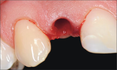
Fig 3 Site 12 after minimally invasive extraction of the fractured tooth 12.
-
No risk of scar-tissue formation; protection of the papillae due to the flapless approach.
-
Minimal trauma significantly reduces pain and post-operative swelling.
-
Patient’s wish for a fixed provisional restoration can be fulfilled.
-
Time-saving procedure, as the provisional crown can be inserted on the day of implant placement.
-
Sufficient bone volume apical to the alveolus allows for the insertion of a 14-mm-long implant to achieve primary stability.
-
The thickness of the buccal bone wall was such that there was a reduced risk of resorption.
-
Healthy periodontal status, thus no loss of bone tissue around the teeth adjacent to the implant site.
The socket walls were carefully examined and found to be intact, so that a Straumann Bone Level implant (endosseous diameter 4.1 mm, length 14 mm, Regular Cross-Fit prosthetic platform) was placed according to the immediate placement protocol (Type 1) (Fig 4).
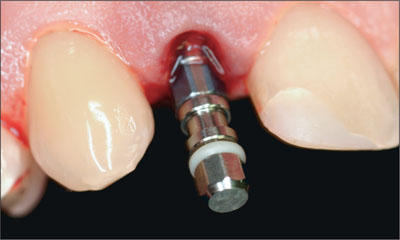
Fig 4 The implant in place with the transfer piece still attached.
The implant was placed in a slightly palatal position to ensure primary stability (Fig 5).
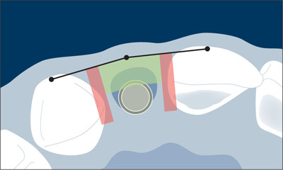
Fig 5 Orofacial and mesiodistal position of the Bone Level implant in the extraction socket in relation to the comfort zones and danger zones. Note the slightly palatal position of the implant.
Primary stability had been achieved, so the decision to immediately restore the implant was confirmed. The blood clot between the slightly palatally located implant body and the buccal bone wall would further add to the sufficient thickness of the labial bone wall as soon as it transformed into bone. This also ensured the stability of the buccal bone plate and thus of the peri-implant soft tissues.
In the apicocoronal dimension, the implant shoulder was placed flush with the bone crest. In the mesiodistal dimension, care was taken to leave a minimum distance of 1.5 mm between the implant and the neighboring tooth roots (Fig 5).
Immediately after implant placement, the impression for the fabrication of a provisional crown was taken. To do so, a Regular CrossFit (RC) impression post for open tray impressions was attached to the implant (Fig 6a). Subsequently, a previously prepared custom vacuform impression tray, filled with pattern resin, was placed on the patient’s teeth (Fig 6b).
Figs 6a-b Impression with an RC impression post and pattern resin immediately after implant placement.
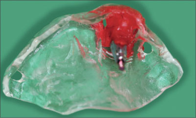
Fig 7 Final impression with the RC impression post ready to be transferred to the dental lab for the fabrication of the provisional crown.
After impression-taking, a periapical control radiograph was taken (Fig 8).
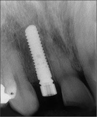
Fig 8 Periapical post-implantation radiograph with the RC temporary abutment connected to the implant.
The impression was transferred to the dental laboratory, where a provisional screw-retained crown was fabricated on the basis of an RC temporary abutment (Figs 9 and 10). To facilitate the fabrication of the provisional, the dental technician used a denture tooth, which he trimmed down to transform it into a veneer. This “shell” was then polymerized onto the customized RC temporary abutment.
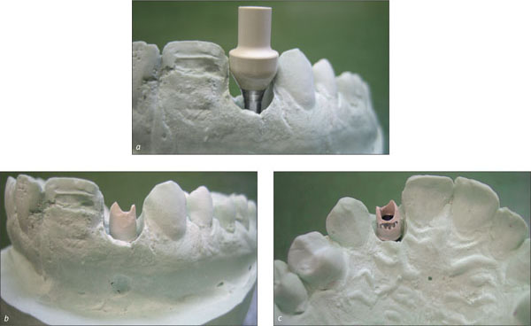
Figs 9a-c Shaping of the RC temporary abutment for the fabrication of the provisional crown.
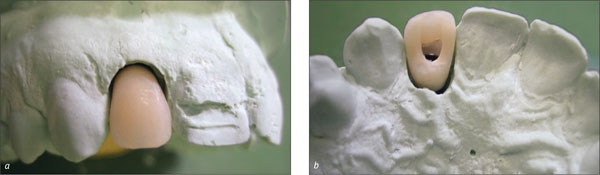
Figs 10a-b The screw-retained provisional crown on the master model, labial and palatal views.
Subsequently, a splint was made and sent to the dental practice together with the provisional crown (Fig 11).
Figs 11a-b The provisional crown and the splint, ready to be sent to the dental practice.
The patient was instructed to wear the splint for 2 months, both day and night, to avoid the transmission of chewing and biting forces onto the crown and implant. Even though the provisional crown was taken out of occlusion and articulation, the splint helped to prevent unintended loading of the implant, especially at night. In addition, the patient was asked to follow a soft diet for 4 weeks and not to bite with the provisional crown for at least 2 weeks.
The fabrication of the crown was performed very quickly, so that it could be incorporated only 3 hours after implant placement (Fig 12).
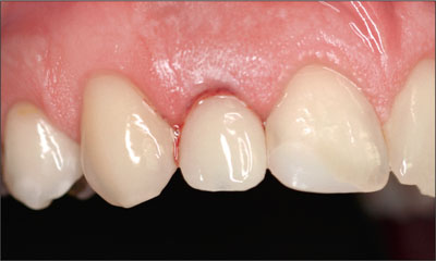
Fig 12 The provisional crown in situ, 3 hours after implant placement.
In summary, in this patient, the following advantages were seen in connection with the immediate (Type 1) placement and immediate non-functional loading protocol performed (Ganeles and Wismeijer, 2004; Quinlan and coworkers, 2005):
-
Reduction of surgical trauma to a minimum.
-
Esthetically pleasing, fixed provisional restoration on the day of implant placement.
-
Significant reduction of the overall treatment time.
-
Conservation of the existing soft-tissue profile.
-
Optimal availability and preservation of existing bone.
It must be kept in mind, however, that the prerequisites for this surgical protocol were an intact and inflammation-free alveolus and a bone volu/>
Stay updated, free dental videos. Join our Telegram channel
VIDEdental - Online dental courses


