Chapter 4 Biomedical-Engineering Analyses of Mini Dental Implants
Biomechanical Perspectives Relevant to the Use of Mini Implants
A Primer on Forces and Moments
Predicting Forces and Moments on Dental Implants
The Issue of Safe Versus Dangerous Loading
Biomaterial and Bioengineering Considerations in Conventional Implant and Mini Implant Design
Biomechanical Perspectives Relevant to the Use of Mini Implants
As will be clear to anyone reading recent journals on dental implants, the implant field is highly dynamic, with many new implant systems being developed and used along with many different loading protocols for implants (e.g., single-tooth versus full-arch restorations; delayed versus immediate loading). Although we do have the beginnings of a biomechanical basis for predicting how loads are supported by dental implants and how these loads create stresses and strains to the surrounding bone, none of these load-prediction methods has been thoroughly tested and verified against actual in vivo data from patients, nor do we yet have a deep understanding of exactly what stress and strain states should be avoided—or perhaps even promoted—in bone around an implant. Hence, considerably more needs to be done to better understand implant biomechanics and the full implications of implant loading in relation to bone biology at the bone-implant interface. That said, progress has been made.
The use of mini implants has been evolving in this biomechanical context. This chapter outlines some biomechanical ideas pertaining to all oral and maxillofacial implants, including mini implants. Unfortunately, in-depth discussion of important topics such as load-sharing among multiple implants supporting bridgework, stress and strain, material failure, stress transfer at the bone-implant interface, and interrelationships between bone biology and mechanical loading, etc., are beyond the scope of this introductory chapter; recent publications can be consulted if a reader wants more detailed information about these and other topics.1-3 Useful topics to help understand the performance and potential of mini implants include the following:
Review of Osseointegration
There is an implicit biomechanical meaning of the term osseointegration. Brånemark and Skalak4 originally noted that an oral implant may be called osseointegrated if “it provides a stable and apparently immobile support of a prosthesis under functional loads without pain, inflammation, or loosening.” Going farther, a second definition suggested that an implant may be termed osseointegrated if “there is no progressive relative motion between the implant and surrounding living bone and marrow under functional levels and types of loading for the entire life of the patient.” Third, from a microscopic, biophysical point of view:
… osseointegration implies that, at the light microscopic and electronmicroscopic levels, the identifiable components of tissue within a thin zone of an [implant] surface are identified as normal bone and marrow constituents that continuously grade into normal bone structure surrounding the fixture [implant]. This implies that mineralized tissue is found to be in contact with the [implant] over most of the surface within nanometers [1 nm = 10-9 m] so that no functionally significant intervening material exists at the interface.4
Beyond these attempts at definitions, the literature has established that the osseointegration approach has allowed highly predictable, long-term functional clinical performance of implant-supported prostheses in both fully and partially edentulous patients. However, it cannot be over-emphasized that this statement applies mainly to the use of commercial purity titanium screw-shaped implants of a typical size of roughly 3.75 mm diameter × 7-18 mm in length and mainly refers to clinical studies with implants used in the so-called delayed loading protocol, where the implants are not built into full function until about 4 to 6 months after surgical implantation. On the other hand, there is accumulating—but not always conclusive—evidence of comparable performance in immediate (as opposed to delayed) loading.5
First, it is well known that bone healing can be disturbed if the clinical conditions of implant use permit excessive relative motion (also called micromotion) at the bone-implant interface during the early healing period. A more detailed discussion of relative motion appears elsewhere.1,6–9 But the basic idea is that micromotion occurs when an implant has excessive instability, if it is not fixed firmly enough within the surgical site, therefore allowing relative motion of the implant with respect to the bony site when the implant is either directly or indirectly loaded. Observations show that a consequence of such early, postoperative implant instability in the wounded surgical site is that the interface does not heal via bone regeneration but instead attempts to repair itself with nonmineralized fibrous tissue encapsulation—the latter being an undesirable result because such fibrous tissue is not as predictable as osseointegration for implant function in the long term. Interestingly, evidence exists that formation of fibrous tissue in cases of micromotion is largely independent of the biomaterial used for the implant,10 but otherwise a full understanding is still lacking about the exact type and amount of micromotion that leads to such nonosseous tissue formation and the cell and molecular mechanisms underlying such tissue formation. Currently the focus of much research, micromotion is especially pertinent to the increased interest in immediate loading of implants, which carries the risk for implant micromotion.
The second biomechanical problem that can occur with any implant is that a successfully healed-in and functioning implant can still be lost if the implant is subsequently “overloaded.” That is, it has been observed11–14 that if there are excessively large forces and/or moments on the implant, there can be a progressive loss of interfacial bone-implant contact, which can worsen in a period of weeks to months if the excessive loading conditions continue unabated; eventually the implant and/or interfacial bone fails, and the implant can no longer function as a fixed support for a prosthesis. As with relative motion, the cellular and molecular details underlying failure by overload have yet to be fully determined, although strain levels in the bone and the bone remodeling cycle are likely candidates.3
A Primer on Forces and Moments
• First, what are the forces and moments on the prosthesis and supporting implants?
• Second, during early case planning (or after the prosthesis is inserted on existing implants), how can we predict the load distribution across the one or more implants that support the prosthesis? What factors influence the load distribution among the implants?
• Third, what are safe versus dangerous loads on implants and surrounding bone?
Forces and Moments on Implants
Forces
The masticatory muscles act to move the jaws during mastication, which allows the teeth to produce forces to crush food into particles. Defined loosely as a push or a pull, a force is measured in the units of pounds (lb, in the U.S. Customary System of Units) or Newtons (N, in the Système International d’Unités or SI system), with 1 lb converting to 4.448 N. Force is a vector quantity, meaning that its definition includes both magnitude and direction. For example, a 10-lb force acting downward on a tooth or implant does not have the same effect as a 10-lb force acting sideways. The intuitive idea that chewing forces always act parallel to the long axes of teeth and implants is an oversimplification; although it is often true that the largest component of a force is the vertical component, the vertical component is not necessarily the only component; it depends also on the facets and inclines on the surface of the crown or prosthesis.
Moments (Torques)
Another essential concept is the idea of a moment or torque. A moment or torque is a loading action that tends to rotate a body. Most commonly, moments on a body such as an implant or a tooth are produced by the actions of forces. So why is the concept of moments needed in the first place? The explanation is that moments are inherent in the definition of equilibrium of a rigid body; that is, for static equilibrium of a rigid body, the sum of forces must be zero along with the sum of the moments about any point. So moments are inherent in defining equilibrium. The dimensions of a moment are force multiplied by distance; hence, typical units are N·m or N·cm in the SI system, and lb·ft or oz·in in the U.S. Customary System. Examples of moments arise in the use of an ordinary screw driver, where a hand supplies a pair of equal and opposite forces (called a couple or couple-moment) to the screwdriver handle, which tends to turn the screwdriver; there is also usually a small axial “pushing” force that is usually directed along the axis of the screwdriver. Just focusing on the torquing action on the screwdriver’s handle, that couple or couple-moment is a good example of a moment, or torque, around the axis of the screwdriver. A similar situation arises when one uses a torque wrench with a handle, where the torque around the axis of the screw or nut that is being turned is created by a force on the handle multiplied by the perpendicular distance from the line of action of the force to the axis of the screw. In a more clinically relevant example of a moment, a lateral force of, 10 N acting 7 mm above the level of a conventional Brånemark-style screw joint abutment would produce a moment of 70 N·mm, or 70 N·cm, at the base of the abutment. To illustrate the significance of this magnitude of a moment, a traditional Brånemark system abutment plus gold cylinder and gold screw tends to undergo opening at about 50 N·cm, so the 70 N·cm is actually large enough to cause a problem.15 Although in mechanics a moment is a vector quantity, it serves our purposes to simply speak of the moment around a point as being a scalar magnitude equal to the force times the perpendicular distance between the point and the force’s line of action.
Biting Forces In Vivo
Normal human patients without dental implants or dentures, and with opposing natural teeth in health, can typically exert axial components of biting force in the range of 100 to 2400 N, which is 27 to 550 lbs in English units (Table 4-1). However, exact bite force values depend on location in the mouth, nature of the food, chewing versus swallowing, degree of exertion by the patient, presence or absence of parafunctional habits of the patient, etc. The term axial refers to the force component acting parallel to the long axis of a natural tooth or implant. Axial force components on natural teeth tend to be larger at more distal locations in the mouth, which is explained by idealizing the mandible as a class 3 lever, in which all forces (i.e., those due to biting, joint reaction force at the temporomandibular joint [TMJ], and jaw muscle forces) are assumed to act in the sagittal plane.
| Description of Data | Typical Values | Reference |
|---|---|---|
| Vertical component of biting force in adults, averaged over several teeth | 200-2440 N | Craig39 |
| Vertical component of biting force in adults, molar region | 390-880 N | Craig39 |
| Vertical component of biting force in adults, premolar region | 453 N | Craig39 |
| Vertical component of biting force in adults, incisor region | 222 N | Craig39 |
| Vertical component of biting force in adults wearing complete dentures | 77-196 N | Meng and Rugh40, Ralph41, Colaizzi et al.42, Haraldsson et al.43 |
| Vertical component of biting force in adults with a maxillary denture opposed by natural teeth in mandible | 147-284 N | Meng and Rugh40 |
| Vertical component of biting force in adults with dentures supported by implants (patients asked to exert max force) | 42-412 N (median 143 N) | Carlsson and Haraldsson44 |
| Vertical component of biting force in adults with dentures supported by overdenture attachments | 337-342 N | Meng and Rugh40 |
| Lateral components of bite forces in adults | ~ 20 N | Graf45 |
| Frequency of chewing strokes | 60-80 strokes/min | Harrison and Lewis46 |
| Rate of chewing | 1-2 strokes/sec | Ahlgren47, Graf45 |
| Duration of tooth contact in one chewing cycle | 0.23-0.3 sec | Graf45 |
| Total time of tooth contact in a 24-hr period | 9-17.5 min | Graf45 |
| Maximum closure speed of jaws during chewing | 140 mm/sec | Harrison and Lewis46 |
| Maximum contact stresses on teeth | 20 MPa | Carlsson48 |
Typical magnitudes of axial forces on natural teeth during mastication (see Table 4-1) should be regarded only as rough estimates for the typical magnitudes of axial forces on natural teeth in humans. One limitation of these data is that the experimental methods by which they were obtained can sometimes change the details of chewing so that the resulting data do not necessarily pertain to natural chewing events. Accordingly, the data in Table 4-1 represent what might best be termed as closure forces (i.e., forces exerted on an object when the patient closes the teeth on the object); these data at least provide some “ball-park” estimates of the magnitudes of expected axially-directed biting forces in vivo.
Data on the lateral force components in the natural or restored human dentition are scarce (see Table 4-1). One study reported that typical lateral components were approximately 20 N for the special case of a prosthesis in the first mandibular molar region. This value is relatively small compared with typical axial force components as detailed in Table 4-1. Because axial forces during biting can also end up acting on the curved occlusal surfaces of teeth or crowns over implants, it is possible that the lateral component of such a force could end up being on the order of 100s of N; therefore for design purposes with implants, it could be prudent to assume that lateral forces on teeth and implants could sometimes be as large as this.
Common experience shows that biting is a dynamic (time-varying) process rather than a static event. Table 4-1 shows that the maximum closure speed of the mandible relative to the maxilla is estimated at about 140 mm/sec. While this speed appears to be moderately fast, nevertheless, a working assumption of most mechanical analyses of implants is that dynamics and related inertial effects are not significant at such closing speeds and do not appreciably affect biting loads. This means that analyses based on statics alone appear to be sufficient for most design purposes.
The net “chewing time per meal“ has been found to be about 450 sec (see Table 4-1), so if the chewing frequency is about 1 Hz with a 0.3-sec duration of tooth contact during each chewing stroke, chewing forces will act on teeth approximately 9 min per day. If other activities such as swallowing are considered, the time might increase to about 17.5 min per day. Obviously, these are estimates only. Parafunctional habits such as bruxism could significantly increase this time.
Values of Moments In Vivo
Moments develop on implants largely from the action of forces, as noted earlier. As with forces, there are components of the moment vector, for instance, components about the occlusoapical, buccolingual, and mesiodistal axes in the mouth. Unfortunately, few studies have determined typical values of moments applied in vivo to implants in various sorts of clinical situations. From direct measurements by several groups working with human subjects having implants16–20 and from simulations with finite element models,21,22 it is known that typical values of the buccolingual and mesiodistal bending moments can be in the range of 0 to 40 N·cm, with maximal values estimated in computer models as large as 70 N·cm. Values for the moment component about the long axis of an implant are of the order of 10 N·cm. So far, these data at least serve as a guide to the expected moments on implants in various situations in the mouth.
Predicting Forces and Moments on Dental Implants
A First Example
Given information on the biting forces, the problem then becomes to estimate the loadings on multiple supporting abutments (natural teeth or implants). The methods here are not very dependent on the exact type of implant being used. In general, for a multiple implant case, the force on an abutment will not be the same as the bite force exerted on the prosthesis. A quick way to see that this is true comes from the following example. Suppose a downward force P acts at the end of an implant prosthesis with a cantilever section (Figure 4-1). The distance between the line of action of P and the nearest implant (#2 in the diagram) is a, the length of the cantilever portion of the prosthesis. The bridge is assumed to be a rigid (undeformable) body supported by two implants (#1 and #2) that are spaced b apart. The problem is to predict the forces on implants #1 and #2.
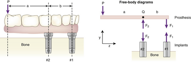
The simplest solution to this problem is to use a model involving rigid-body static equilibrium in two dimensions (2D). The analysis starts with a free body diagram of the prosthesis, which is drawn in Figure 4-1 as a simple beam at the top right of the figure. This beam is isolated (removed from the implants), and all forces acting on the beam are shown. (The beam is assumed to have no appreciable weight.) Forces F1 and F2 represent the forces that the implants exert on the beam. The true directions of the forces do not have to be known at this stage of the analysis; the correct directions will emerge from the solution. (However, in this example the forces are drawn in the actual directions in which they act.) The assumption that only forces—and no moments—exist at the prosthesis-implant connection(s) comes from the idealization that the implants are connected to the prosthesis by pin-joints in this 2D model; pin-joints transmit only force components and not moments. (In the 3D analog of this example, a ball and socket joint would be the comparable connection.) Force P is the biting force. The next step is to recognize that the beam is in static equilibrium, which means, according to Newton’s Laws, that the sum of the forces and the sum of the moments on the beam are each equal to zero. The application of equilibrium allows us to solve for the two unknown forces F1 and F2, which is done by solving the two equations of static equilibrium (note sign conventions according to the coordinate system in Figure 4-1):
 (1)
(1) (2)
(2)The above analysis has several important messages. First, it shows that although the bridge is loaded by a biting force of magnitude P, the implants are loaded by forces for which the magnitudes can be larger than P, depending on the ratio a/b. For example, if a/b = 2—which is not an uncommon value in clinical practice—the forces on the implants will be 3P and 2P. Second, the analysis shows that the forces F1 and F2 do not act in the same direction; implant #2, nearest to the point at which P acts, experiences a compressive load (tending to push it into the bone), while implant #1 experiences a tensile load (tending to pull it out of the bone). So the key result from this introductory analysis is that the forces on the implants can sometimes exceed the value of the biting force on the prosthesis.
A numerical example helps drive home the point: If we have a moderately low biting force P of 250 N, and an a/b ratio of 2, then the tensile force on implant #1 will be 2P = 2 × 250 N = 500 N, whereas the compressive force on implant #2 is 3P = 3 × 250 N = 750 N. As a quick indication of the clinical significance of such force levels on dental implants, it is known that implant loadings of 250 to 500 N can exceed the absolute failure strength of many implants that have been tested in various animal models. Two examples of this are Block and Kent23 measured maximal pull-out strengths of about 150 N for hydroxyapatite (HA)-coated cylindrical implants that had healed in dog mandibles for 32 weeks, and Burgess et al.24 measured mean pullout forces of about 200 N to 350 N at 3 weeks and 15 weeks, respectively, after implanting cylindrical HA-coated implants in dog bone. Although many factors influence the strength of the bone-implant interface, including healing time, cancellous versus cortical bone site, and size and shape of the implant,1 unfortunately, for human cases the implant field does not yet have an extensive database of strengths of bone-implant interfaces for various implants in different types of bone quality and quantity, etc. However, exactly this sort of database is part of what is needed to establish safe versus dangerous applied force levels on implants.
More Complicated Examples
• A full or partial prosthesis; number and location of implant (and/or natural tooth) abutments; angulations of the implants; nature of the bridge-abutment connection; use of overdentures supported by a mixture of soft tissue and implants, etc.
• The mechanical properties of the material(s) and structure of the bridge or prosthesis, implants, and bone (e.g., elastic moduli, structural stiffnesses); deformability of the mandible or maxilla; misfit of the prosthesis relative to the supporting implants.
There is now a large literature on these factors, and only a limited discussion is supplied here with a few examples to illustrate how the models work. Generally, models for predicting implant loading fall into two categories. The first category includes analytical models—those that provide explicit equations allowing calculation of implant loading via pencil and paper, pocket calculator, or personal computer. A good example of this sort of model is the Skalak model from the early 1980s.25 The second category of model consists of more complica/>
Stay updated, free dental videos. Join our Telegram channel
VIDEdental - Online dental courses


