4 Achieving Optimal Esthetic Results
4.1 Surgical Considerations for Single-Tooth Replacements in the Esthetic Zone: Standard Procedure in Sites Without Bone Deficiencies
D. Buser, W.C. Martin, U.C. Belser
The following case demonstrates the general principles of implant placement in the esthetic zone:
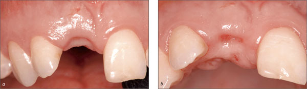
The patient had a missing upper left central incisor, which he had lost by trauma. At full natural smile, the patient exhibited a high lip line situation and a harmoniously scalloped gingival margin (Fig 1).
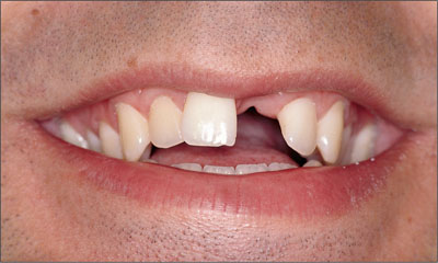
Fig 1 The patient’s smile, revealing a high lip line situation.
The tissue biotype was thin and highly scalloped (Fig 2). In general, the combination of a high lip line and a thin-gingiva biotype is considered a high-risk situation from an anatomic point of view. Patients with such a risk profile should be treated with caution.
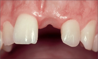
Fig 2 Single-tooth gap caused by a dental trauma. Edentulous span and alveolar crest adequately dimensioned for implant therapy.
The periapical radiograph of the single-tooth gap, taken in May 1996, demonstrated adequate bone height and the absence of pathological processes (Fig 3).
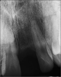
Fig 3 Periapical radiograph showing normal bone structures in the edentulous gap.
Consensus Statement B.2
Patient Selection:
Appropriate patient selection is essential in achieving esthetic treatment outcomes. Treatment of high-risk patients identified through site analysis and a general risk assessment (medical status, periodontal susceptibility, smoking, and other risks) should be undertaken with caution, since esthetic results are less consistent.
Consensus Statement B.1
Planning and Execution:
Implant therapy in the anterior maxilla is considered an advanced or complex procedure and requires comprehensive preoperative planning and precise surgical execution based on a restoration-driven approach.
In complex cases, a diagnostic waxup can be beneficial as a basis for fabricating a surgical template (Fig 4), which facilitates correct three-dimensional implant placement during surgery. Here, the cervical end of the template in the tooth-gap position indicated the desired future soft-tissue margin at the implant-supported crown.
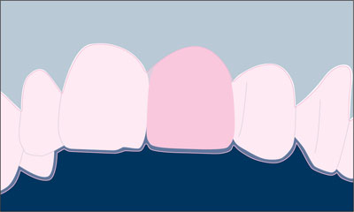
Fig 4 Schematic diagram of a waxup that can be used for the fabrication of a surgical template.
Esthetic implant placement is based upon a restoration-driven philosophy. Correct three-dimensional implant positioning will allow for optimal support and the stability of the peri-implant hard and soft tissues (Buser and coworkers, 2004).
Consensus Statement B.3
Implant Selection:
Implant type and size should be based on site anatomy and the planned restoration. Inappropriate choice of implant body and shoulder dimensions may result in hard and/or soft tissue complications.
In the anterior maxilla, the implant types of the Straumann Dental Implant System shown in Table 1 are recommended for clinical use.
| Implant | Description |
 |
Standard Plus implant Endosseous ∅ 4.1 mm Regular Neck (∅ 4.8 mm) |
 |
Standard Plus implant Endosseous ∅ 4.8 mm Regular Neck (∅ 4.8 mm) |
 |
Standard Plus implant Endosseous ∅ 3.3 mm Narrow Neck (∅ 3.5 mm) |
 |
Tapered Effect implant Endosseous ∅ 4.1 mm Regular Neck (∅ 4.8 mm) |
 |
Tapered Effect implant Endosseous ∅ 3.3 mm Regular Neck (∅ 4.8 mm) |
These implants differ in restorative shoulder diameter and endosseous diameter. To use these implants successfully in the anterior maxilla, correct implant selection relative to the mesiodistal dimension of the tooth to be replaced (gap size) is critical (Table 2).
| Implant Type | Shoulder Diameter (mm) | Minimum Gap Size (mm) | Ideal Gap Size (mm) |
| Implants with a Regular Neck (∅ 4.8 mm) | 4.8 | 7.0 | 8.0-9.0 |
| Implants with a Narrow Neck (∅ 3.5 mm) | 3.5 | 5.5 | 6.0-7.0 |
Wide Neck implants, with their 6.5-mm shoulder diameter, are not recommended for use in the anterior maxilla. Their implant shoulder margin is likely to be located too close to adjacent teeth or too far facially, encroaching on their respective danger zones.
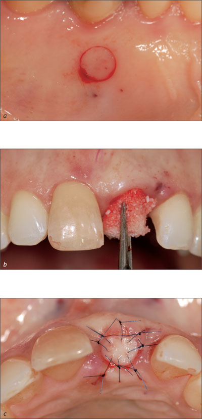
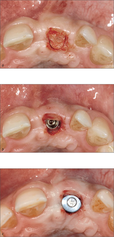
Under local anesthesia, a full thickness flap was created with a crestal incision located approximately 2-3 mm toward the palatal aspect (Figs 5, 6). The relieving incisions were placed at the distal line angles of the neighboring teeth.
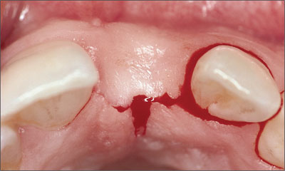
Fig 5 Occlusal view of the crestal incision, which is positioned 2-3 mm palatally.
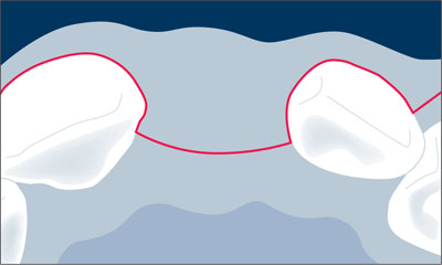
Fig 6 Schematic drawing of the crestal incision.
The flap was extended through the sulcus of the adjacent teeth, ascending to the facial aspect of the alveolar crest with divergent distal line angle relieving incisions (Figs 7, 8). These incisions avoid the formation of scar tissue in the mid-crestal area and ensure sufficient vascularization of the facial flap, especially in the area of the future papillae.
Fig 7 Divergent distal line angles relieving incisions are often used to allow the incision of the periosteum and subsequent tension-free primary soft-tissue closure.
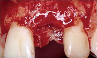
Fig 8 Clinical status following flap elevation.
Alternatively, a para-papillary incision technique could have been used.
The facial and palatal mucoperiosteal flaps were elevated with a fine tissue elevator to allow low-trauma soft-tissue handling.
Following flap elevation, the surgical site was carefully analyzed. Special attention was paid to the evaluation of the facial aspect of the alveolar crest, since sufficient bone volume in this area is an important prerequisite for an esthetic treatment outcome (Fig 8).
A periodontal probe was placed on the facial surface of adjacent teeth to examine if the facial bone wall was flattened in relation to adjacent teeth (Fig 9). Furthermore, in implant sites in the central incisor area, the location of the nasopalatal foramen needed to be determined.
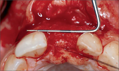
Fig 9 Periodontal probe indicating no horizontal bone deficiency. The site did not require horizontal bone augmentation.
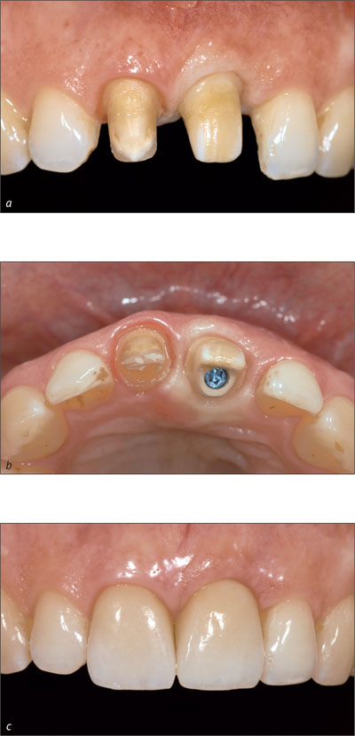
A bone-scalloping procedure was performed in order to facilitate an easier and more precise preparation of the implant bed (Fig 10).
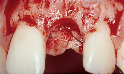
Fig 10 Clinical status following bone scalloping. The bone crest at the adjacent teeth is not touched.
The scalloping procedure smoothens the alveolar crest and imitates its natural shape. This helps visualize and control the optimal implant position and facilitates precise implant-bed preparation.
Consensus Statement A.2
Single-Tooth Replacement:
For anterior single-tooth replacement in sites without tissue deficiencies, predictable treatment outcomes, including esthetics, can be achieved because tissue support is provided by adjacent teeth.
No bone should be removed in the proximal area of the adjacent teeth, because this bone is important for the support and maintenance of the papillae (Fig 11).
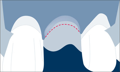
Fig 11 Schematic drawing of the bone scalloping procedure in this single-tooth gap.
Although not mandatory for implant placement in single-tooth gaps, the use of surgical templates in the anterior maxilla can be valuable for properly placing the implant shoulder in a position that will allow for an ideal emergence profile and long-term peri-implant hard-tissue and soft-tissue support (Higginbottom and Wilson, 1996). A diagnostic waxup highlighting the final gingival margin position, facial surface, and embrasure form of the proposed restoration indicates these positions and should be the basis for generation of the surgical template. The template imitates the future soft-tissue margin at the implant crown (Fig 12).
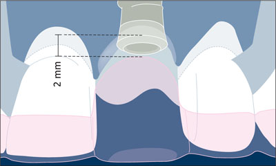
Fig 12 The future soft tissue margin at the implant crown as imitated by the template served to place the implant shoulder in the ideal position.
Furthermore, the spiral drill is guided by the surgical template for proper alignment of the implant.
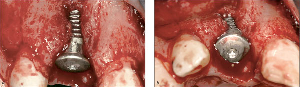
After implant placement, the implant shoulder was located in the desired, formerly planned position about 2 mm apical to the future soft-tissue margin around the implant-supported crown (Fig 12).
The placement of implants in a correct three-dimensional position is one of the keys to an esthetic treatment outcome, regardless of the implant system used. The correct three-dimensional position is dependent upon the planned restoration that the implant will support (Belser and coworkers, 1996; Belser and coworkers, 1998; Buser and von Arx, 2000). The relationship of the position between the implant and the proposed restoration should be based upon the position of the implant shoulder, since it will influence the final hard and soft tissue response. The implant shoulder position can be viewed in three dimensions:
-
Mesiodistal
-
Orofacial
-
Coronoapical
Consensus Statement B.4
Implant Positioning:
Correct three-dimensional implant placement is essential for an esthetic treatment outcome. Respect of the comfort zones in these dimensions results in an implant shoulder located in an ideal position, allowing for an esthetic implant restoration with stable, long-term peri-implant tissue support.
When planning for an ideal three-dimensional implant position, a distinction is made between “comfort” and “danger” zones in each dimension (Buser and coworkers, 2004). The selection of the implant type and the placement of the dental implant should be based on the restorations planned in these zones. If implant shoulders are positioned within the danger zones, complications such as peri-implant bone resorption followed by soft-tissue recession may occur, resulting in esthetic complications. Implants positioned in the comfort zones provide the basis for a long-term stable esthetic restoration. Comfort and danger zones are defined in the mesiodistal, orofacial, and coronoapical dimensions.
4.1.1 Mesiodistal Dimension
In the mesiodistal dimension, the danger zones (red color) are located next to the adjacent root surfaces. This danger zone is about 1.0-1.5 mm wide (Fig 13).
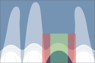
Fig 13 Correct implant position in the mesiodistal comfort zone (green).
With the tulip shape of the implant shoulder on Straumann implants, this places the implant body surface no closer than 1.5 mm to the adjacent root surfaces.
Proper mesiodistal implant placement avoids the danger zones adjacent to the neighboring teeth (Figs 14, 15).
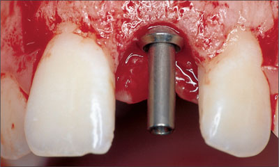
Fig 14 Status following implant insertion. The implant shoulder is positioned in the comfort zone.
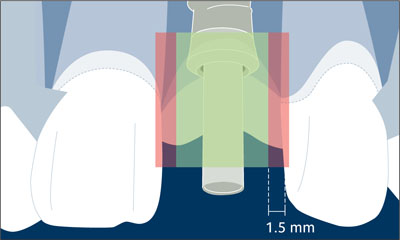
Fig 15 Schematic drawing with the comfort and danger zones in mesiodistal direction.
Placing the implant shoulder too close to an adjacent tooth can cause the resorption of the interproximal alveolar crest to the level of that of the implant (Esposito and coworkers, 1993). With the loss of the interproximal crest height comes a reduction in papillary height. This also creates restorative problems: poor embrasure forms and emergence profiles will result in restorations with long contact zones and a compromised clinical outcome. The loss of crest height at adjacent teeth is caused by the bone saucerization routinely found around the implant shoulder of osseointegrated implants. Bone loss occurs in both the horizontal and vertical dimensions, creating a circumferential bone saucer around the implant.
Because the horizontal dimension of this resorption area measures about 1.0-1.5 mm from the implant surface (Fig 16), this minimal distance needs to be respected at implant placement to prevent vertical bone loss on adjacent teeth.
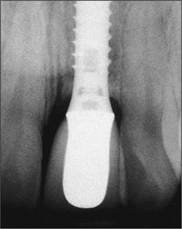
Fig 16 The typical radiographic appearance of a bone saucer around a Straumann implant with a vertical and a horizontal component.
With regard to the coronoapical position of the implant shoulder, the vertical dimension of the bone saucer will lead to undesired bone loss if the implant is placed too far apically. When measured from the microgap, this vertical dimension amounts to approximately 2 mm (Hermann and coworkers, 1997; Hermann and coworkers, 2000) in interproximal areas (Fig 17). This may affect the height of the facial bone wall as well and can lead to undesired soft-tissue recession in this extremely important esthetic zone.
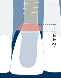
Fig 17 Schematic drawing of the radiographic appearance of a bone saucer around a Straumann implant.
4.1.2 Orofacial Dimension
In the orofacial dimension, the implant shoulder should be positioned in the comfort zone (green color). The comfort zone measures about 1.5-2.0 mm in width when measured from the ideal point of emergence. The danger zones (red color) are located both facially and palatally to the comfort zone (Fig 18).
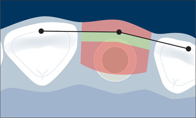
Fig 18 Schematic drawing of the orofacial comfort and danger zones.
The facial danger zone is entered when the implant is placed too far facially, i.e. facially of an imaginary line connecting the point of emergence of adjacent teeth. An implant in the facial danger zone will result in the potential risk of soft-tissue recession, since the thickness of the facial bone wall is clearly reduced by the malpositioned implant. In addition, potential prosthetic complications could result in restoration—implant axis problems, making the implant difficult to restore.
The palatal danger zone is entered when the implant is placed more than 2 mm palatal to this imaginary line, since this implant position often results in a restoration with a ridge-lap design (Belser and coworkers, 1998).
After the implant bed is prepared, the facial bone wall should be intact. It should ideally measure at least 2 mm in thickness. This is important to ensure proper soft-tissue support and to avoid the resorption of the facial bone wall following restoration (Fig 19).
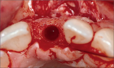
Fig 19 Occlusal view following implant bed preparation with a proper orofacial implant position and an intact facial bone wall.
The implant shoulder should be positioned in the orofacial comfort zone. (Fig 20).
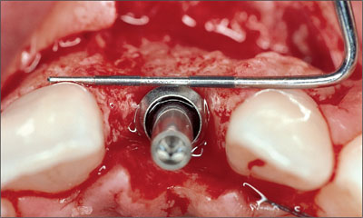
Fig 20 Periodontal probe visualizing the correct position of the implant shoulder in orofacial direction.
4.1.3 Coronoapical Dimension
In the coronoapical dimension, the comfort zone is a narrow band of about 1 mm. Ideally, the shoulder of a Straumann implant should be positioned about 1 mm apical to the cemento-enamel junction (CEJ) of the contralateral tooth (Buser and von Arx, 2000; Buser and coworkers, 2004). This recommendation, however, is only valid for teeth without periodontal tissue loss (Fig 21).
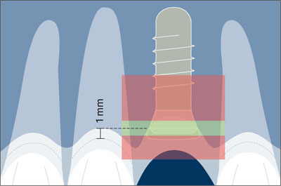
Fig 21 Comfort and danger zones in the coronoapical dimension.
This ideally results in an implant shoulder located approximately 2 mm apical to the mid-facial gingival margin of the implant restoration (Figs 22, 23).
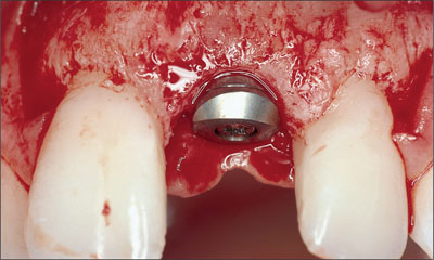
Fig 22 Correct implant placement in a coronoapical direction.
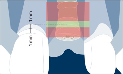
Fig 23 Schematic drawing illustrating the comfort and danger zones in the coronoapical dimension.
This can be accomplished through a surgical template highlighting the gingival margin of the planned restoration (Higginbottom and Wilson, 1996).
In patients without vertical tissue deficiencies, the use of a periodontal probe leveled on the adjacent CEJs in single-tooth gaps has proven to be a valid alternative (Buser and von Arx, 2000).
It is important to note that the CEJ of adjacent teeth can vary depending on the tooth to be replaced, and must be taken into consideration. In particular, lateral incisors are smaller and their CEJ is normally located more coronally compared to the CEJ of central incisors or canines. Implant placement within the apical danger zone (located anywhere 3 mm or further apically of the proposed gingival margin) can result in undesired facial bone resorption and subsequent gingival recession. The coronal danger zone is invaded with a supragingival shoulder position leading to a visible metal margin and poor emergence profile.
The use of a short, beveled healing cap facilitated a tension-free adaptation of the facial flap over the implant site towards the palatal aspect (Fig 24).
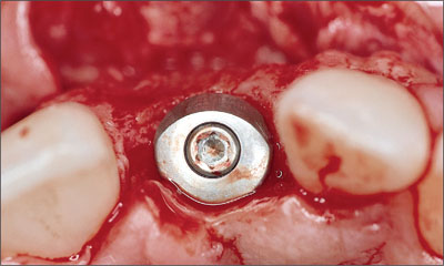
Fig 24 Occlusal view of the implant site with the inserted implant and a beveled healing cap.
In patients without local bone defects and no need for bone grafting procedures, soft-tissue grafting can be used to improve the thickness and contour of the facial mucosa.
Consensus Statement B.5
Soft-Tissue Stability:
For long-term esthetic soft-tissue stability, sufficient horizontal and vertical bone volume is essential. When deficiencies exist, appropriate hard and/or soft tissue augmentation procedures are required. Currently, vertical bone deficiencies are a challenge to correct and often lead to esthetic shortcomings. To optimize soft tissue volume, complete or partial coverage of the healing cap/implant is recommended in the anterior maxilla. In certain situations, a non-submerged approach can be considered.
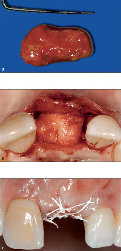
If required, a free connective-tissue graft can be used from the palate at implant placement (Figs 25, 26). As implants are increasingly placed into non-healed extraction sockets, the frequency of soft tissue grafting has dropped significantly in the past five years, whereas more and more implants in the esthetic zone are placed in combination with a simultaneous guided bone regeneration (GBR) procedure.
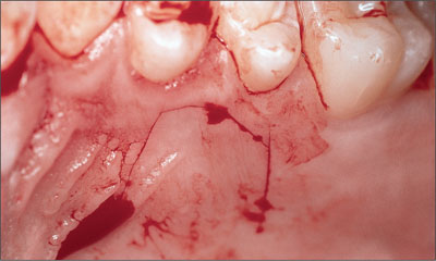
Fig 25 Harvesting site opened with a mucosal incision in the premolar area of the palate.
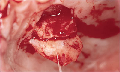
Fig 26 Harvesting a small connective-tissue graft following elevation of a mucosal flap.
Returning to our case, the graft was placed on the facial aspect of the implant site in order to check its shape and position (Fig 27).
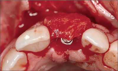
Fig 27 Positioning the connective-tissue graft.
The graft was sutured to the periosteum of the mucoperiosteal flap to avoid displacement during wound closure (Fig 28). Suturing also ensured close and secure contact with the facial flap, thus facilitating proper vascularization.
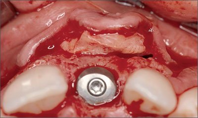
Fig 28 Occlusal view demonstrating the soft-tissue graft sutured to the mucoperiosteal flap.
In most cases, the incision of the periosteum is necessary to mobilize the flap coronally, and to obtain a tension-free primary wound closure using 5-0 and 6-0 non-resorbable, atraumatic suture material (Fig 29).
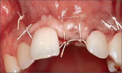
Fig 29 Status following a tension-free primary wound closure.
The mucoperiosteal flap was precisely repositioned for submerged healing. Precise repositioning of the flap margins is especially important in the area of the future papillae.
After surgery, the existing partial denture was shortened and put in place (Fig 30).
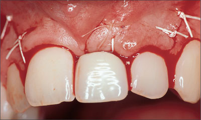
Fig 30 Insertion of the shortened partial denture after completion of surgery.
The provisional restoration should not exert any pressure on the soft tissues. In general, interim restorations that are fixed to adjacent teeth are more beneficial for implant integration and soft-tissue maintenance, since they eliminate the possibility for undesired soft-tissue contact. They, however, are more difficult to handle for the clinician.
Following surgery, a periapical radiograph was taken to examine the position and direction of the implant and its relationship to the roots of adjacent teeth (Fig 31).
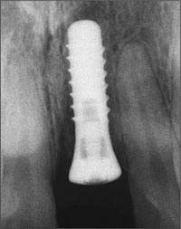
Fig 31 Post-surgical radiograph indicating a correct implant position.
During the soft-tissue healing period of two to three weeks, chemical plaque control with chlorhexidine digluconate (0.1%) is normally performed. Follow-up visits are recommended after 7, 14, and 21 days.
After six weeks, bone healing for implants with an SLA (Sandblasted, Large-grit, Acid-etched) surface will have sufficiently progressed in standard sites without peri-implant bone defects. In implant sites where a simultaneous bone-augmentation procedure was performed, a healing period of eight to twelve weeks is required, depending on the extent and morphology of the bone defect present at the time of implant placement.
The restorative phase started after soft-tissue healing and successful osseointegration of the implant.
Consensus Statement A.4
Newer Surgical Approaches:
Currently, the literature regarding esthetic outcomes is inconclusive for the routine implementation of certain surgical approaches, such as flapless surgery and immediate or delayed implant placement with or without immediate loading in the anterior maxilla.
At the completion of bone healing, the soft tissues were healthy. The soft tissue in the implant site displayed an excellent convex contour and favorable color (Fig 32).
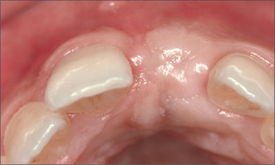
Fig 32 Occlusal view of the implant site before the reopening procedure.
The implant site was reopened with a punch technique using a 12b blade to gain access to the implant shoulder. Following removal of the short healing cap, a long healing cap was inserted to establish a soft-tissue “tunnel” from the implant shoulder to the soft-tissue surface (Fig 33).
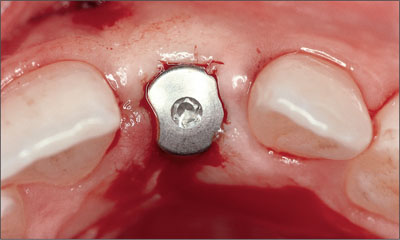
Fig 33 Status following the reopening procedure and insertion of a long titanium healing cap.
Instead of a long healing cap, a provisional restoration may be instantly inserted using a chairside technique to initiate the important phase of soft-tissue conditioning.
A few days after reopening, the soft tissues had healed uneventfully so that the restorative phase could be started (Fig 34).
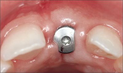
Fig 34 Clinical status a few days after the reopening procedure.
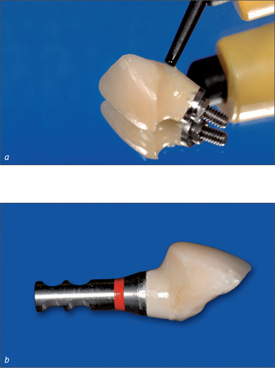
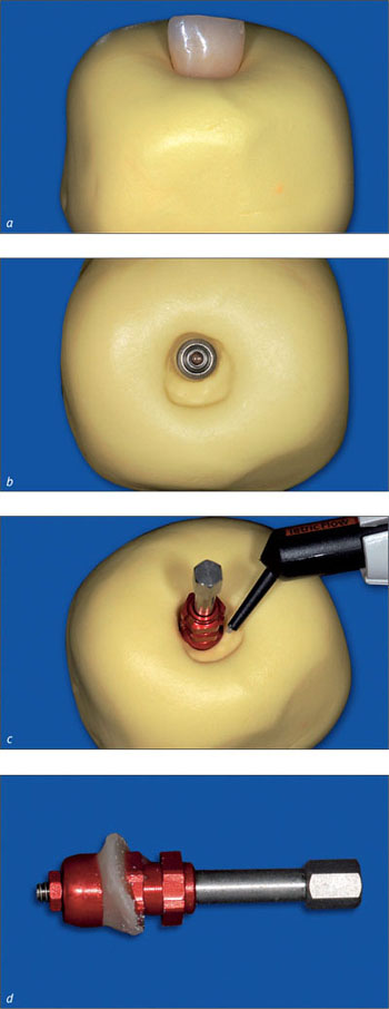
For impression-taking, the use of a screw-retained transfer system is recommended in esthetic sites to ensure a precise and reproducible transfer of the implant position from the mouth to the master cast.
An acrylic-resin provisional crown, based on a prefabricated screw-retained titanium post for temporary restorations, ensured the shaping of esthetic peri-implant soft-tissue contours.
The periapical radiograph demonstrates the precise seating of the screw-retained provisional crown (Fig 35).
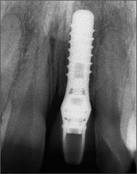
Fig 35 The periapical radiograph shows a good fit between the implant and the screw-retained provisional restoration.
The phase of soft-tissue conditioning usually takes three to six months. Before the insertion of the final implant-supported superstructure, the peri-implant soft tissue should present optimal three-dimensional contours.
In this patient, the provisional crown remained in place for three months to create ideal contours (Figs 36, 37). The final treatment outcome with a screw-retained ceramo-metal crown was pleasing for the patient, and integrated harmoniously into the natural dentition (Fig 38). The periapical radiograph demonstrated stable peri-implant bone crest levels (Fig 39).
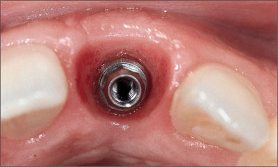
Fig 36 Occlusal view with nicely shaped peri-implant soft tissue.
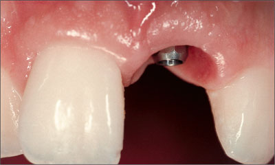
Fig 37 Facial view with nicely scalloped gingival margin.
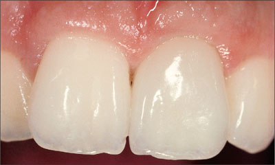
Fig 38 Esthetically pleasing treatment outcome with the implant-supported ceramo-metal crown.
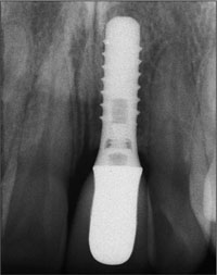
Fig 39 Periapical radiograph showing excellent precision between the implant and the restoration.
The long-term follow-up demonstrated excellent stability of esthetic peri-implant soft tissues for up to nine years. In particular, the facial mucosa maintained its convex contour and the height of the midfacial gingival margin without any recession (Figs 40-43).
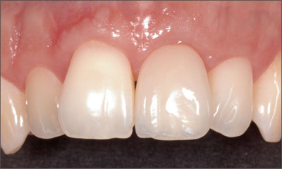
Fig 40 Clinical status eight years after implant placement.
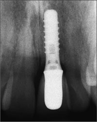
Fig 41 The radiographic follow-up at eight years showed excellent stability of the bone crest levels.
Fig 42 Clinical smile. The esthetic treatment outcome continues to be pleasing (December, 2005).
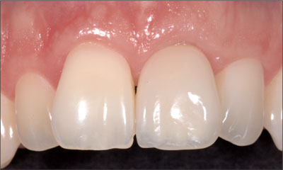
Fig 43 The detail view confirming the stability of the esthetic result at the nine-year follow-up.
4.2 Prosthetic Management of Implants in the Esthetic Zone: General Principles and Scientific Documentation
C. Hämmerle, R. Jung
When teeth in the esthetic zone are lost, implants often represent the therapy of choice. The patient will not only request restitution of health and function, but will also place strong emphasis on the esthetic outcome. In order to meet these expectations, the surgical and the prosthetic procedures need to be conducted using state-of-the-art methods and techniques. Because patients are interested in a pleasing appearance of their teeth and mucosa, surgical and prosthetic procedures need to be closely interlinked.
In recent years, there has been increasing evidence that a restoration-driven treatment concept is the key to achieving optimal outcomes in the esthetic zone.
What are the accepted criteria for considering a given treatment outcome an “esthetic success”? The third ITI Consensus Conference (Proceedings of the Third ITI Consensus Conference 2004) gave the following answer:
Statement C.1
Standards for an Esthetic Fixed Implant Restoration
An esthetic implant prosthesis was defined as one that is in harmony with the perioral facial structures of the patient. The esthetic peri-implant tissues, including health, height, volume, color, and contours, must be in harmony with the healthy surrounding dentition. The restoration should imitate the natural appearance of the missing dental unit(s) in color, form, texture, size, and optical properties.
As stated by the third ITI Consensus Conference (Proceedings of the Third ITI Consensus Conference 2004) and illustrated in Chapter 3 and Section 4.1, proper patient selection, sound treatment planning, and correct three-dimensional implant placement following a restoration-driven approach are the basis for achieving esthetic treatment outcomes that remain stable over time.
Consensus Statement B.1
Planning and Execution
Implant therapy in the anterior maxilla is considered an advanced or complex procedure and requires comprehensive preoperative planning and precise surgical execution based on a restoration-driven approach.
Consensus Statement B.2
Patient Selection
Appropriate patient selection is essential in achieving esthetic treatment outcomes. Treatment of high-risk patients identified through site analysis and a general risk assessment (medical status, periodontal susceptibility, smoking, and other risks) should be undertaken with caution, since esthetic results are less consistent.
An important aspect of the prosthetic management of esthetic sites is related to the appropriate timing of implant loading. This is based on the fact that both the patient and the clinical team have a desire to reduce the overall treatment time.
The patient’s individual risk profile as introduced in Chapter 3 of this book is the basis for the decision-making process in regard to the time of implant loading. It has to be kept in mind that the the primary objectives are to reach the treatment goals and to minimize the associated risk. Delayed loading (3-6 months after implantation) is therefore preferred in critical situations in order to minimize treatment risk. The topic of loading protocols in implant dentistry will be addressed in Volumes II and III of the ITI Treatment Guide and is not discussed in detail here.
The soft tissues around implant-supported prostheses are of primary importance for an esthetic treatment outcome. Esthetic peri-implant soft tissues are characterized by good tissue health and appropriate volume, color, and contours in harmony with the healthy surrounding tissues.
Keratinized peri-implant mucosa also integrates better with the surrounding structures than non-keratinized mucosa, from an esthetic point of view. The clinical team should therefore aim at establishing keratinized mucosa around a dental implant (Figs 1a-c; Alpert, 1994; Saadoun and coworkers, 1994; Landsberg, 1997; Jung and coworkers, 2004).
Figs 1a-c A punch graft transfers keratinized tissue from the palate to the alveolus. A collagen allograft is used to fill the extraction socket for supporting the graft.
Multiple problems such as a lack of buccal soft-tissue height, a lack of papillary height, asymmetries, dislocation of the junction between attached and mobile mucosa, scars, irregular mucosal texture, and discolorations often pose obstacles to achieving optimal esthetics. Furthermore, clinically apparent ridge defects include underlying bony deficiencies in addition to soft-tissue deficits. As for the restorative aspects, three general levels can be identified that need to be taken into consideration in order to obtain an esthetically pleasing implant-supported restoration:
Level 1: Bone contour
Level 2: Soft-tissue contours and texture
Level 3: Prosthesis: contours, position, texture, and color
The underlying bone, the soft tissue, and the superstructure all affect the esthetic outcome. It is therefore recommended that the clinician move from one level to the next. Before or at implant placement, the bone contour is modified according to the existing functional and esthetic requirements. The soft-tissue management is carried out next, comprised of grafting with various techniques and of contouring with appropriate healing caps and provisional restorations. Finally, the prosthesis (“white esthetics”) is fabricated.
Provided that the bone and soft tissue contours were preserved or appropriately optimized during pretreatment (Levels 1 and 2), ideal prerequisites are now established for the fabrication of an esthetic implant superstructure.
The soft-tissue contouring process is initiated before or at the time of implant site re-entry. Soft-tissue recession has to be expected within the first three to twelve months after abutment connection. In transmucosal healing, recession starts developing after implant insertion, whereas in submerged healing, this process begins only after abutment connection. On average, the amount of recession is between 0.6 and 1.6 mm, with considerable variation (Grunder, 2000; Oates and coworkers, 2002; Small and Tarnow, 2000; Ekfeldt and coworkers, 2003).
When it comes to deciding whether a submerged or a non-submerged approach is to be chosen, the following recommendations can be derived from the above literature:
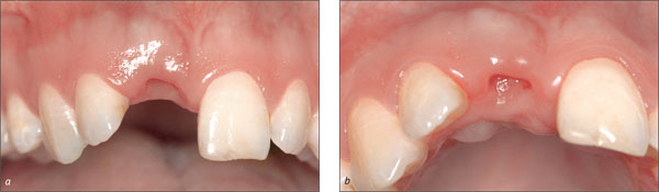
-
In esthetically demanding areas with a thin, highly scalloped gingiva or where extensive soft-tissue or hard-tissue defects are present, submerged healing is recommended in order to establish soft-tissue access (Fig 2).
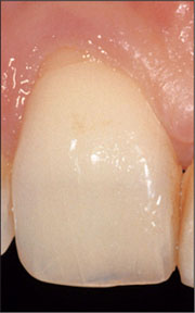
Fig 2 Thin, highly scalloped gingiva, combined with a soft-tissue and hard-tissue defect.
-
In esthetically demanding areas with a thick, low scalloped gingiva and soft-tissue access of at least 1-2 mm compared to the contralateral tooth, transmucosal healing can be chosen (Fig 3).
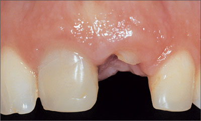
Fig 3 Soft-tissue access allowing for transmucosal healing.
Statement B.5
Soft-Tissue Stability
For long-term esthetic soft-tissue stability, sufficient horizontal and vertical bone volume is essential. When deficiencies exist, appropriate hard and/or soft-tissue augmentation procedures are required. Currently, vertical bone deficiencies are a challenge to correct and often lead to esthetic shortcomings. To optimize soft-tissue volume, complete or partial coverage of the healing cap/implant is recommended in the anterior maxilla. In certain situations, a non-submerged approach can be considered.
Soft-tissue management can be carried out at different times relative to implant placement and abutment connection:
-
Before implant placement: in situations with extensive soft-tissue deficits (Figs 4a-c).
Figs 4a-c Forced orthodontic eruption is applied to enlarge soft-tissue and hard-tissue volume.
-
At implant placement with submerged healing: standard procedure for the correction of soft-tissue problems.
-
At abutment connection with submerged healing or at implant placement with transmucosal healing (for the correction of minor soft-tissue problems only) (Figs 5a-c).
Figs 5a-c A semilunar incision and subsequent rolling of a de-epithelialized pedicle flap in a buccal direction. Tissue loss is avoided and the labial soft-tissue contour is improved.
-
After placement of a temporary or final reconstruction (in exceptional cases only).
Soft-tissue corrections before implant insertion may be necessary in rare cases to allow secure implantation, whereas additional soft tissue can more easily be incorporated directly at the time of implantation. In the majority of cases, soft-tissue corrections are performed after implant placement, since the exact implant position and the amount of augmented bone are only clear at this time (Figs 6a-c).
Figs 6a-c A connective tissue graft is placed 6 weeks after implantation in order to improve the soft-tissue contours.
Soft-tissue defects that remain after implant placement are corrected before or at the time of healing cap/abutment connection.
Earlier protocols for abutment connection describe a punch technique under local anesthesia to gain access to the implant shoulder (Lekholm, 1983). This excision technique does not consider factors such as the mucosal thickness, the soft-tissue profile, or the course of the transition line between keratinized and non-keratinized mucosa. In addition, precious soft tissue is sacrificed by this technique. In order to maintain as much tissue as possible and to minimize the risks, resection techniques are usually avoided.
The following overview of implant exposure (reentry) techniques for abutment connection can be given:
-
Punch technique (only where abundant volume and width of keratinized mucosa are present)
-
Crestal or paracrestal incision of the keratinized mucosa with apical positioning of the vestibular mucosa
-
Roll technique utilizing mini-flaps
The reentry procedure can also be considered an opportunity to influence the keratinized mucosa with respect to contour and volume by applying reconstructive techniques. Accordingly, reentry does not merely serve the purpose of uncovering the implant and choosing appropriate healing caps, but it is also an opportunity for establishing of functional and esthetic peri-implant soft tissue.
During the subsequent wound healing and soft-tissue maturation period, the new soft-tissue situation is supported and stabilized by the healing cap and the provisional crown. It is important to note that there are very few chances left to manipulate the soft-tissue contours after the insertion of the provisional or the final crown. At that stage, vertical augmentation is no longer possible. A deficient slight soft-tissue volume can be remedied using inlay-grafting techniques (Fig 5). Hence, it is important to anticipate soft-tissue problems before the insertion of healing caps or provisionals. There are hardly any options for corrections after that point.
Bearing the above in mind, the aims of the abutment-connection procedure can be summarized as follows:
In traditional implant dentistry:
-
Creation of a connection of the dental implant to the oral cavity
In esthetic implant dentistry additionally:
-
Assessment of the bone volume surrounding the implant after guided bone regeneration (GBR) procedures and, if required, membrane removal
-
Widening of the band of keratinized mucosa
-
Relocation of the mucogingival border
-
Enlargement of the volume of the buccal/labial mucosa in order to improve the ridge contour (root prominence)
-
Augmentation of interproximal soft tissues for papilla reconstruction
The circular profile of most healing caps differs from the rather triangular profile of the cervical portion of the tooth to be reconstructed. Hence, adjustments in shape need to be made in order to create a natural, esthetic emergence profile. This can best be achieved by temporary crowns or by the final restoration with the desired shape and contour.
From a biological point of view and with regard to tissue stability over time, a provisional crown is not mandatory. This assertion is based on the observation that the papillae adjacent to single-implant restorations present similar volume two years after crown insertion, regardless of the types of the abutments used (healing cap or provisional resin crown; Jemt and coworkers, 1999). The same study also demonstrated that the shape of the peri-implant soft tissues was achieved more quickly using provisional crowns than with healing caps.
Consensus Statement C.4
Use of Provisional Restorations
To optimize esthetic treatment outcomes, the use of provisional restorations with adequate emergence profiles is recommended to guide and shape the peri-implant tissue before definitive restoration.
In addition, temporary crowns are also valuable in diagnostics with regard to the (future) peri-implant soft-tissue esthetics as well as to the ideal shape of the final crown. Therefore, it is highly recommended to use provisional crowns in esthetic sites.
It can be advantageous to adapt the shape of the provisional crown at chairside. This allows the establishment of the ideal shape, size, and contour in a single step or in multiple steps. This can be done by subtracting (Paul and Jovanovic 1999) or by adding temporary material (Figs 7a, b). Depending on the desired emergence profile and the quality of the mucosa, one to three conditioning steps, i.e. modifications of the shape of the crown, are necessary (Touati, 1995; Potashnick, 1998; Vogel, 2002). Within six to eight weeks, this process leads to the final soft-tissue contour (Hinds, 1997; Vogel, 2002).
Figs 7a, b The cervical portion of the provisional crown is reshaped at chairside.
Maturation and stabilization of the peri-implant mucosa around a provisional crown take place within the first three to twelve months after insertion (Grunder, 2000; Oates and coworkers, 2002; Small and Tarnow, 2000; Ekfeldt and coworkers, 2003). It is therefore recommended that the provisional crown remain in situ for at least three months.
When the desired shape and emergence profile are achieved (Fig 8), the impression for the master cast and the final crown fabrication is taken.
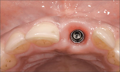
Fig 8 The contours of the mucosa for a natural emergence profile, which were shaped by the provisional, can now be captured with the impression.
A so-called individualized impression that transfers the emergence profile by use of an impression cap is advantageous in esthetic sites (Figs 9a-d).
Figs 9a-d An extraoral impression of the provisional crown is used to transfer the desired emergence profile to the impression cap.
It precisely captures the emergence profile of the final provisional crown and thus accurately communicates the desired clinical situation to the dental technician (Figs 10a-b).
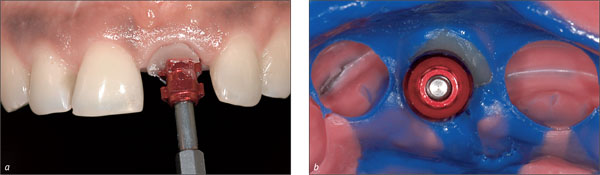
Fig 10a-b The individualized impression cap supports the mucosa during impression taking and enables the dental technician to fabricate the optimal shape of the final crown.
In the following situations, the use of a provisional crown is highly recommended:
-
Patient has high expectations regarding the esthetic treatment outcome and/or optimal esthetics
-
Patient presents thin, highly scalloped gingival biotype
-
Need for additional diagnostics regarding the shape or position of the planned reconstruction
In summary, the timing of the soft-tissue conditioning process from the first impression to incorporation of the final crown is as follows (Fig 11):
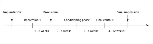
Fig 11 Timing of the soft-tissue conditioning process in esthetic sites.
The transition zone, i.e., the emergence profile created from the shoulder of the implant to the soft-tissue margin, can either be conditioned by a transocclusally screw-retained crown (provisional or final) or by a mesostructure such as the synOcta gold abutment or the synOcta In-Ceram blank. A mesostructure may be beneficial whenever access to the implant shoulder is difficult to obtain. This is frequently the case in the interproximal areas of the esthetic zone, where the implant shoulder can easily be located 5 or even 6 mm submucosally.
A mesostructure, i.e., an individualized abutment, not only serves to condition the mucosa in the transition zone, but it also displaces the margin of the crown coronally (Fig 12). Thus, the margin of the crown is located closer to the soft-tissue margin for better access to effectively remove the cement used for seating crown (Higginbottom and coworkers, 2004). Furthermore, a mesostructure may help compensate for a non-ideal implant axis.
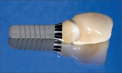
Fig 12 Individualized zirconia abutment and all-ceramic crown. The shape of the crown margin is favorable, facilitating effective cement removal.
When a mesostructure is used, it is recommendable to try in this mesostructure in order to optimize the position and shape of the future crown margin (Fig 13). This ensures pleasing esthetics and facilitates thorough cement removal.
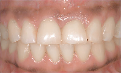
Fig 13 After adhesive cementation of the all-ceramic crown 21, harmonious integration into the natural dentition could be observed.
Consensus Statement C.5
Location of the Implant Shoulder
In most esthetic areas, the implant shoulder is located subgingivally, resulting in a deep interproximal margin. This shoulder location makes seating of the restoration and removal of cement difficult. Therefore a screw-retained abutment/restoration interface is advisable to minimize these difficulties.
The biocompatibility of the various abutment materials used also plays an important role. Commercially pure titanium as well as aluminum oxide and zirconia ceramics are the abutment materials of choice (Figs 14a-c).
Figs 14a-c In-Ceram blank at site 21, frontal and incisal view, and final situation with all-ceramic crown on tooth 11 and all-ceramic implant-supported superstructure at site 21.
An epithelial attachment has been shown to form on these materials, resulting in stable peri-implant tissue.
By contrast, soft-tissue recession and cervical bone resorption have been found with gold and ceramic veneer (Abrahamsson and coworkers, 1998; Kohal, 2004).
Another important aspect is the mechanical properties of the materials. High-strength ceramic materials such as densely sintered aluminum oxide or zirconia exhibit fracture resistance values high enough for these materials to be used intraorally (Lüthy, 1996; Seghi and coworkers, 1995).
The thickness of the peri-implant mucosa is also a critical factor for the selection of the appropriate abutment material. In situations where the thickness was larger than 2.5 mm, the color of the abutment did not negatively influence the color of the mucosa (Hämmerle and coworkers, 2005). It may be be surmised that in esthetically demanding locations in combination with a mucosal thickness below 2.5 mm, ceramic abutments avoid possible negative influences on the esthetic treatment outcome. Further research, however, is required before clear-cut clinical recommendations can be made.
Acknowledgment
The authors express their special thanks to master dental technician Ana Suter for her expert technical work presented in this chapter.
4.3 Decision Trees: Prosthetic Options
U.C. Belser
The decision trees* for Regular Neck (RN) and Narrow Neck (NN) implants presented in this chapter were developed to illustrate, in a structured manner, the possible prosthetic options available in a given clinical situation once the implant has been inserted. In this context, the specific design of both the provisional crown and the final superstructure, whether screw-retained or cemented, and their respective restorative components (abutments, mesostructures, secondary and tertiary components) are graphically presented.
* For the decision-tree posters, please see the inside back cover.
The different prosthetic options suggested in the decision trees relate primarily to the individual implant position, which includes both implantation depth as well as implant axis.
The options suggested reflect the recommendations of the third consensus conference (group on esthetics) and do not claim to be “general rules.”
The decision trees are not meant to provide a complete list of all available restorative components of the Straumann Dental Implant System, nor do they represent a definite hierarchy of prosthetic options. They reflect the authors’ personal opinion, which is based on clinical experience.
The options based on ceramics (whether screw-retained or cemented) were listed as the first options in order to take into account the most recent developments in anterior implant prosthodontics (CAD/CAM technology, ZrO2). This does not put ceramo-metal restorations in the position of “second choice” by any means.
Blank fields for specific combinations of implant depths and orofacial implant axes represent theoretical options for superstructures that, in the opinion of the authors, are less recommendable, even if they are theoretically possible.
Since the rational choice of the most appropriate material (titanium/gold alloys/ceramics) in a specific given situation was discussed in detail in section 4.2 “Prosthetic Management of Implants in the Esthetic Zone,” this discussion will not be revisited in this section.
4.3.1 Regular Neck Implants
The Regular Neck implant decision tree* is structured in matrix form. The top row represents, from left to right, the three possible vertical implant shoulder positions (i.e., ideal, deep, superficial) and secondly an axial-position problem. By definition, this last aspect can be “superimposed” on any of the three preceding situations. The columns reflect the possible restorative options relative to implant shoulder depth and implant axis, in the following order:
* For the decision-tree posters, please see the inside back cover.
-
Provisional implant restorations (screw-retained/cemented)
-
Definitive implant restorations
-
All-ceramic restorations, screw-retained
-
All-ceramic restorations, cemented
-
Ceramo-metal restorations, screw-retained
-
Ceramo-metal restorations, cemented
-
We deliberately limited this decision tree to the two variables “implantation depth” and “orofacial axial-position problem,” because we consider that the remainder of theoretically possible implant positioning „errors” such as:
-
Position too far mesial/distal
-
Position too far labial/palatal
-
Axial-position problem in the frontal plane
These errors should not occur under normal conditions.
As mentioned above, certain fields were left blank, indicating this that specific restorative option cannot be recommended, given the particular implant-shoulder depth or orofacial axial-position problem:
Row 3: In case of a significantly protruding implant axis, a transocclusally screw-retained all-ceramic solution is literally impossible.
Row 4: In case of a superficial implant shoulder position, an all-ceramic restoration cemented on a CARES custom abutment cannot be recommended, as the respective cemented interface would be located too close to the labial mucosal margin.
Rows 5, 6, and 7: In case of a superficial implant-shoulder position or an orofacial axial-position problem, a transocclusally screw-retained ceramo-metal restoration cannot be recommended, as the metal margin would be too close to the mucosal margin and the screw access channel would be located on the labial aspect of the restoration.
Rows 8 and 14: In the absence of an orofacial axial-position problem, the use of an angulated abutment does not make sense.
Rows 9 and 10: In case of a deep or a superficial implant shoulder position, a transversally screw-retained restoration is not recommended, as in the first case the screw-access channel may be located submucosally, and in the second case, this same screw-access channel may interfere with the occlusion.
Rows 11 and 12: In case of a superficial implant shoulder position, the use of a CARES titanium custom abutment or a synOcta gold abutment as a mesostructure for a cemented ceramo-metal restoration is not recommended, as the cemented interface would be too close to the labial mucosal margin.
Row 13: In case of an ideal or a deep implant shoulder position, a ceramo-metal restoration cemented on a prefabricated solid abutment cannot be recommended, as the interproximal crown margins are inaccessible and the resulting cement excess is difficult to remove.
It should generally be noted, however, that a ceramo-metal implant shoulder is theoretically also possible in case of a superficial implant shoulder position (although the respective column was deliberately left blank), provided the dental technician has the requisite know-how and skills to produce a metal margin of only minimal width (no more than 0.2-0.4 mm). If this is an option, visible metal margins can usually be avoided.
4.3.2 Narrow Neck Implants
The Narrow Neck implant decision tree* has also been structured in the form of a matrix. The top row represents, from left to right, first the three possible vertical implant shoulder positions – ideal, deep, superficial – and secondly an axial-position problem in orofacial direction. As per definition, this last aspect can be “superimposed” on any of the three preceding situations. The vertical columns reflect the possible restorative options relative to implant shoulder sink depth and implant axis, in the following order:
* For the decision-tree posters, please see the inside back cover.
-
Provisional implant restorations (screw-retained/cemented)
-
Definitive implant restorations
-
Ceramo-metal restorations, screw-retained
-
Ceramo-metal restorations, cemented
-
A ceramic abutment (ZrO2) for use with Straumann CARES, the Computer Aided REstoration Service, will be available in 2007.
We have deliberately limited this decision tree to the two variables “implantation depth” and “orofacial axial-position problem,” as we consider that the remainder of the theoretically possible implant positioning “errors” should not occur under normal conditions:
-
Position too far mesial/distal
-
Position too far labial/palatal
-
Axial-position problem in the frontal plane
As mentioned above, certain fields have been left blank, indicating that this specific restorative option cannot be recommended, given the particular implant shoulder depth or orofacial axial-position problem:
Rows 4 and 5: In case of a significant orofacial axial-position problem, a transocclusally screw-retained ceramo-metal restoration cannot be recommended, as the screw-access channel would be located on the labial aspect of the restoration.
Rows 6 and 8: In case of a superficial implant shoulder position or an orofacial axial-position problem, a cemented ceramo-metal restoration cannot be recommended, as in the first case the cemented interface lies too close to the soft-tissue margin, and in the second case the underlying abutment would not provide adequate retention/resistance form after having corrected the axial-position problem.
Row 7: In the absence of an orofacial axial-position problem, the use of an angulated abutment does not make sense.
4.4 Replacement of an Upper Right Central Incisor with a Regular Neck Implant, Restored with an All-Ceramic Crown, Transocclusally Screw-Retained
R. Jung
This 37-year-old female patient, a non-smoker, complained about discomfort and gingival problems at tooth 11. She was in good general health, and her medical history was without significant findings.
The clinical inspection of the oral cavity revealed a fistula originating at tooth 11 (Fig 1).
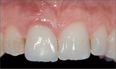
Fig 1 The fistula buccally of tooth 11 is clearly visible.
Radiological examination of the crowned tooth 11 revealed a root-canal filling, status after apicoectomy, and a large periapical bone defect, as well as secondary caries (Fig 2).
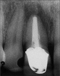
Fig 2 Radiograph of tooth 11 with periapical pathology.
The adjacent teeth, 21 and 12, were periodontally healthy. They had interdental composite fillings that the patient wanted replaced. The bone crest levels of teeth 12 and 21 were well maintained, providing potential soft-tissue support (Fig 3).

Fig 3 The interproximal bone levels are intact. Because of the large periapical radiolucency however, an extensive bone defect had to be anticipated.
The treatment approach would have to ensure that the distance between the interproximal bone crests of the neighboring teeth and the contact with the planned implant-supported superstructure would not exceed 5 mm, as this has been proven to be an important factor for the predictability of the papillae (Tarnow and coworkers, 1992).
Periodontal probing of tooth 11 as well as teeth 12 and 21 showed probing depths not exceeding 4 mm.
The patient’s biotype was medium thick, with a medium scallop height. The soft tissues were free of recessions and other defects. The gingival margin of contralateral tooth 21 was located about 1 mm further apically than that of tooth 11, so there was some “soft-tissue access.” The shape of the tooth crown was rectangular. The shape of the gingival margin was harmonious, as was the shape of the incisal edges, except for the elongated crown of tooth 11.
Clinically, the bony arch presented harmonious contours, but due to the large periapical radiolucency, a bony defect had to be anticipated (Fig 4).
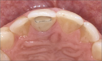
Fig 4 A bony defect was to be expected despite the harmoniously contoured bony arch.
The clinical and radiological findings in this patient add up to the following esthetic risk-profile analysis (Table 1):
| Esthetic Risk Factors | Low | Medium | High |
| Medical status | Healthy patient and intact immune system | Reduced immune system | |
| Smoking habit | Non-smoker | Light smoker (< 10 cig/d) | Heavy smoker (> 10 cig/d) |
| Patient’s esthetic expectations | Low | Medium | High |
| Lip line | Low | Medium | High |
| Gingival biotype | Low scalloped, thick | Medium scalloped, medium thick | High scalloped, thin |
| Shape of tooth crowns | Rectangular | Slightly triangular | Triangular |
| Infection at implant site | None | Chronic | Acute |
| Bone level at adjacent teeth | ≤ 5 mm to contact point | 5.5 to 6.5 mm to contact point | ≥ 7 mm to contact point |
| Restorative status of neighboring teeth | Virgin | Restored | |
| Width of edentulous span | 1 tooth (≥ 7 mm) | 1 tooth (< 7 mm) | 2 teeth or more |
| Soft-tissue anatomy | Intact soft tissue | Soft-tissue defects | |
| Bone anatomy of alveolar crest | Alveolar crest without bone deficiency | Horizontal bone deficiency | Vertical bone deficiency |
The individual esthetic risk profile of this patient shows that this case is to be considered a medium-risk case. This means that a certain esthetic risk is associated with the treatment of this patient concerning the esthetic treatment outcome.
Based upon the clinical and radiological findings and the assessment of the esthetic risk associated with the treatment, a treatment plan was defined with a two-stage treatment protocol, including a guided bone-regeneration procedure and the placement of a Straumann Standard Plus dental implant at site 11.
A full-thickness flap was raised for tooth extraction and bone augmentation. Tooth 11 was extracted (Figs 5, 6).
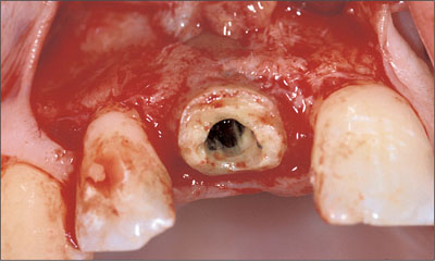
Fig 5 Buccal view of the treatment site after a mucoperiosteal flap was raised. Note the lack of labial bone around the root to be extracted.
Fig 6 After the extraction and removal of the granulation tissue, a large bone defect was present that did not allow for primary implant stability.
A large bone defect was present after the extraction and removal of the granulation tissue. Due to the severe bone resorption caused by the infection, a bone-augmentation procedure needed to be performed before implant insertion (Fig 6). Thanks to the favorable anatomy of the defect and the protective walls of the extraction socket, a bone-augmentation procedure with particulate grafting material and a resorbable membrane was chosen.
Autogenous bone was harvested from the tuberosity area of the left upper quadrant using forceps and chisels (Figs 7, 8). Access to that area is similar to the procedure for extracting a third molar.
Fig 7 Access to the donor site at the tuberosity area was gained with horizontal (tuber), vertical (mesial to tooth 17), and sulcular (tooth 17) incisions and mucoperiosteal flap elevation.
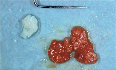
Fig 8 Particulate autogenous bone harvested form the tuberosity area.
The autogenous bone was then applied to the alveolus and subsequently covered with a layer of deproteinized bovine bone mineral (DBBM) (Fig 9).
The augmentation site was then covered with a collagen membrane (Figs 9, 10).
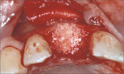
Fig 9 Alveolar defect filled up using the GBR technique and autogenous bone and particles of DBBM as supporting material.
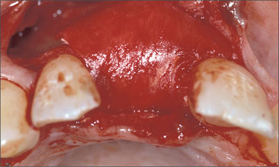
Fig 10 The augmented area was covered with a resorbable collagen membrane stabilized with two resorbable pins in the apical region. Note the over-contoured labial aspect of the prospective implant site.
The augmented area was carefully shaped to the desired contour. The labial aspect of the future implant site was slightly overcontoured to create a favorable bone volume and shape (Fig 11).
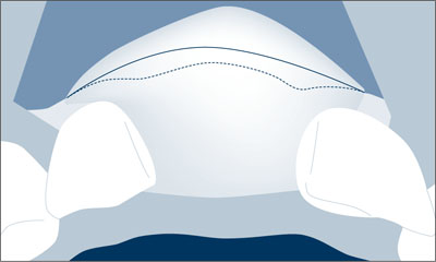
Fig 11 About one-fourth of the volume was overcontoured in order to compensate for the volume reduction caused by soft-tissue pressure.
To facilitate primary wound closure without advancing the buccal flap too far coronally, a rotational pedicle graft was prepared (Fig 12) and rotated over the grafted alveolar region (Fig 13). The graft was prepared by splitting the palatal flap from the distal to the mesial end and leaving the pedicle at the site of the former extraction socket.
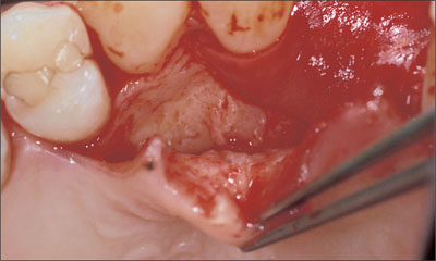
Fig 12 Elevation of the palatal flap for preparation of the split flap from distal to mesial.
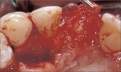
Fig 13 Elevation of the connective-tissue pedicle graft to the site of augmentation.
Six months after augmentation, the site was healthy and stable (Fig 14) and could be reopened for implant placement.
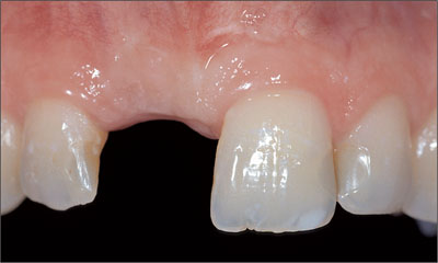
Fig 14 Site 11 six months after primary augmentation.
To ensure good blood supply and to minimize the trauma to the soft tissue, only one vertical relieving incision was made (Fig 15).
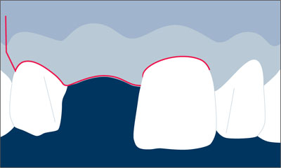
Fig 15 Incision technique: sulcular incision around teeth 12 and 21; crestal incision slightly palatally; vertical releasing incision distally of tooth 12.
As the full-thickness flap was created, care was taken to place the crestal incision slightly palatally to avoid cutting through the tip of the papilla.
Bone volume and contour proved to be favorable as the flap was elevated. The new bone was vital and well supplied with blood. Note the slightly overcontoured bone at the facial aspect (Fig 16).
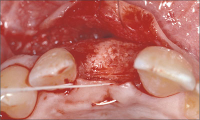
Fig 16 Occlusal view of the regenerated augmented bone area.
A Standard Plus implant was then placed in an ideal three-dimensional position (Figs 17, 19).
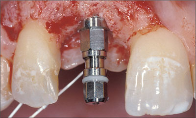
Fig 17 Implant in the correct vertical position.
In the coronoapical dimension, care was taken to place the implant shoulder approximately 1 mm apically of the cemento-enamel junction of contralateral tooth 21 (Figs 17, 18).
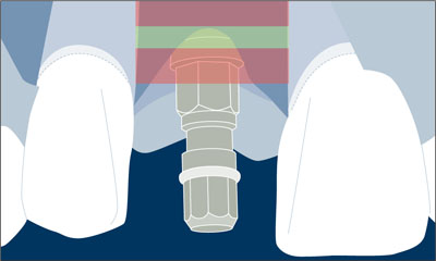
Fig 18 The implant shoulder was located in the coronoapical comfort zone.
Also in the orofacial dimension, the implant shoulder was placed in an ideal position, i.e. about 1 mm palatally of the point of emergence of the adjacent teeth (Figs 19, 20). Note the remaining thickness of the facial bone wall of more than 1 mm.
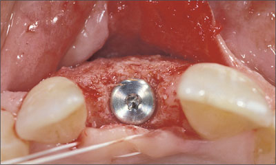
Fig 19 Occlusal view of the correct orofacial position of the implant.
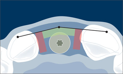
Fig 20 The implant shoulder was located in the orofacial comfort zone.
The implant was covered with a closure screw. The flap was sutured for the implant to osseointegrate in a submerged healing mode. The flap was sutured with non-resorbable ePTFE suture material.
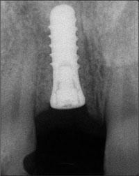
Fig 21 Radiograph of the inserted implant during submerged healing.
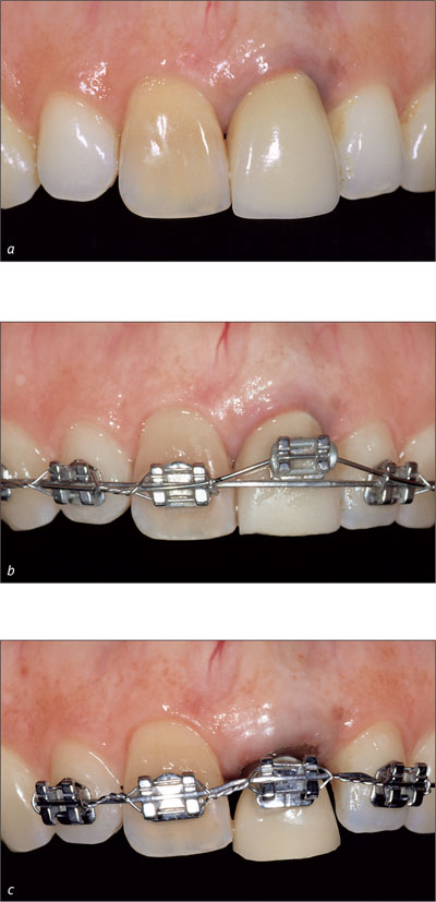
Twelve weeks after implant placement, the closure screw was replaced by a labially beveled healing cap in order to start the mucosa-conditioning phase and to facilitate soft-tissue contouring. Two weeks later, remarkably good soft-tissue access was seen at the facial aspect of the implant site. An impression was taken for a provisional crown (Fig 22).
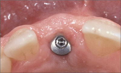
Fig 22 Clinical situation two weeks after abutment insertion.
Four months after the implant was placed, a temporary crown with a moderate emergence profile was fabricated by the dental technician using a titanium post for temporary restorations (Fig 23). At the time of integration of the temporary crown, it is important not to put too much pressure on the soft tissue. Instead, the emergence profile should be moderate, so that it can be modified in one or two subsequent steps. This step-by-step procedure prevents soft-tissue retraction and helps build a perfectly conditioned mucosa to match the emergence line and the contour of the marginal gingiva of the contralateral tooth as closely as possible.
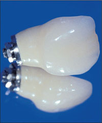
Fig 23 Temporary crown with moderate emergence profile.
The clinical situation immediately after insertion of the temporary crown showed soft-tissue blanching caused by pressure (Fig 24). The temporary crown did not yet have the desired shape, and the line of emergence did not yet match that of the contralateral tooth 21.
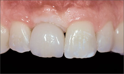
Fig 24 The pressure of the inserted temporary crown caused soft-tissue blanching.
In order to improve the shape and emergence profile, the provisional was modified chairside with a light curing composite material (Fig 25).
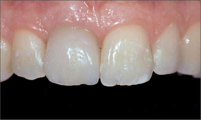
Fig 25 Emergence profile of the provisional as improved by chairside step-by-step modification with light-curing composite.
After a soft-tissue maturation phase of three months, a custom impression cap was produced, capturing the shape of the provisional crown’s cervical portion and transferring it to the prefabricated impression cap (Fig 26).
Fig 26 Modified impression cap capturing the shape of the provisional crown.
At impression-taking, this customized impression coping prevented soft-tissue collapse and ensured optimal support of the emergence profile (Fig 27).
Fig 27 Modified impression coping in place.
The final crown was fabricated at the dental laboratory using a synOcta In-Ceram blank (Fig 28).
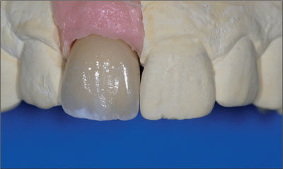
Fig 28 Frontal view of the all-ceramic crown (synOcta In-Ceram blank).
Thanks to the ideal implant axis, a screw-retained crown could be fabricated (Fig 29).
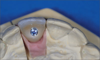
Fig 29 Occlusal view of the screw-retained all-ceramic crown (synOcta In-Ceram blank).
For crown fabrication, the In-Ceram blank was ground to the shape of a miniature copy of tooth 11, which was subsequently glass-infiltrated and directly veneered with a veneering ceramic.
The screw head was sealed off with a thin layer of cotton, and the screw access was finally closed off with a light-curing composite material. The occlusion was carefully checked.
The screw-retained all-ceramic crown harmoniously integrated into the row of natural teeth. Another very important advantage of screw retention was that there was no cement residue after crown cementation (Fig 30).
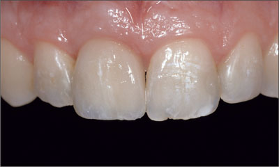
Fig 30 Frontal view of the all-ceramic implant-supported restoration at site 11.
The 2.5-year follow-up photograph confirmed stable peri-implant soft tissues (Fig 31).
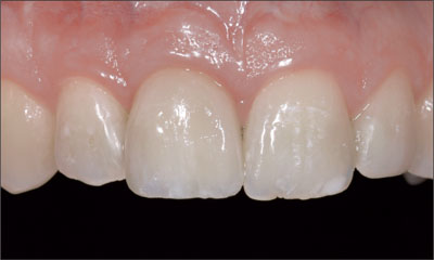
Fig 31 Clinical situation showing favorable soft-tissue contours 2.5 years after crown insertion.
The 2.5-year follow-up periapical radiograph confirmed stable peri-implant bone levels (Fig 32).
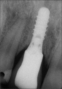
Fig 32 Stable peri-implant bone levels 2.5 years after crown insertion.
Acknowledgments
Prosthetic Procedures
Dr. David Siegenthaler – University of Zurich, Switzerland, Clinic for Dental Crown and Bridge Prosthetics, Partial Prosthetics, and Dental Material Science
Dr. Claudia Holderegger – University of Zurich, Switzerland, Clinic for Dental Crown and Bridge Prosthetics, Partial Prosthetics, and Dental Material Science
Laboratory Procedures
Master Dental Technician Ana Suter – University of Zurich, Switzerland, Clinic for Dental Crown and Bridge Prosthetics, Partial Prosthetics, and Dental Material Science
4.5 Replacement of an Upper Right Central Incisor with a Regular Neck Implant, Restored with (1) an All-Ceramic Crown, Transocclusally Screw-Retained, and (2) an Auro-Galvano Crown, Cemented, Seated on CAD/CAM Custom Mesostructures (ZrO2 and Titanium)
U.C. Belser
In February 2005, a 25-year-old female patient, a non-smoker, was referred to our clinic due to tooth 11 presenting a chronic fistula following unsuccessful root-canal treatment and several attempts at endodontic surgery. The dental history revealed that more than ten years earlier, teeth 11 and 21 had been traumatized during a sports accident. Consequently, 11 had lost its vitality, and there were two moderate fractures of the mesioincisal borders of the two central incisors that had been restored with direct composite restorations.
At the time of examination, the composite restorations showed signs of wear, some discoloration, and marginal infiltration. The patient also complained about a moderate discoloration of the clinical crown of the non-vital tooth 11.
The patient was in good general health, and her medical history revealed no significant findings.
Tooth 11 was considered hopeless (irrational to treat), and implant therapy was the first therapeutic choice, as the neighboring teeth did not require significant restorations.
At full smile, the patient presented a high lip-line situation, completely exposing the anterior maxillary teeth and the associated facial gingival tissue (Fig 1).
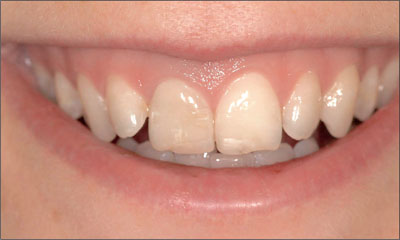
Fig 1 At full smile, the high lip line completely exposed the facial aspect of the anterior maxillary dentition, including the associated gingiva.
The patient’s gingival biotype was thin to medium thick and highly scalloped, at the same time presenting a broad band of keratinized mucosa (Fig 2).
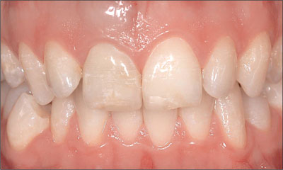
Fig 2 The thin to medium-thick, highly scalloped tissue biotype increased the overall esthetic risk in this patient.
The clinical examination revealed the presence of a chronic fistula apically of tooth 11 (Fig 3).
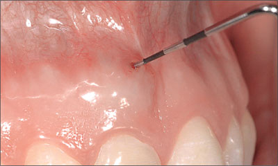
Fig 3 Periodontal probe, confirming the presence of a chronic fistula at the mucogingival border labial of root 11.
The initial radiographic examination documented a status after extensive conventional root-canal treatment followed by an unsuccessful attempt at periapical endodontic therapy, as well as pronounced apical and lateral root resorption. The vertical level of the interproximal bone at the adjacent teeth, however, was still within the physiological distance from the respective cemento-enamel junction (CEJ) of the adjacent teeth. This parameter represents a major prognostic factor for esthetic considerations relative to anterior single-tooth implant therapy (Fig 4).
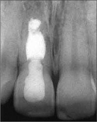
Fig 4 Initial periapical radiograph. Status after extensive conventional root-canal therapy on tooth 11, including an unsuccessful attempt at periapical endodontic surgery. Advanced apical and lateral root resorption. The vertical bone height at adjacent teeth was within two millimeters of the cemento-enamel junction.
The patient’s subjective symptoms at site 11, with chronic pain and a persisting active fistula, and the highly unfavorable radiographic status made it irrational to try to re-treat this tooth. After a comprehensive evaluation of the various treatment options, single-tooth implant therapy was chosen, as it represented the least invasive treatment modality, preserving hard tissue at adjacent teeth, an approach that was highly predictable, also with regard to long-term esthetics (Belser and coworkers, 2003; Belser and coworkers, 2004; Buser and coworkers, 2004; Higginbottom and coworkers, 2004).
The above findings led to the following esthetic risk profile (Table 1), which could be classified as medium to high and was thus associated with a considerable esthetic risk:
| Esthetic Risk Factors | Low | Medium | High |
| Medical status | Healthy and cooperative patient and intact immune system | Reducaed immune system | |
| Smoking habit | Non-smoker | Light smoker (< 10 cig/d) | Heavy smoker (> 10 cig/d) |
| Patient’s esthetic expectations | Low | Medium | High |
| Lip line | Low | Medium | High |
| Gingival biotype | Low scalloped, thick | Medium scalloped, medium thick | High scalloped, thin |
| Shape of tooth crowns | Rectangular | Triangular | |
| Infection at implant site | None | Chronic | Acute |
| Bone level at adjacent teeth | ≤ 5 mm to contact point | 5.5 to 6.5 mm to contact point | ≥ 7 mm to contact point |
| Restorative status of neighboring teeth | 21: minimally restored 12: virgin | Restored | |
| Width of edentulous span | 1 tooth (≥ 7 mm) | 1 tooth (< 7 mm) | 2 teeth or more |
| Soft-tissue anatomy | Intact soft tissue | Soft-tissue defects | |
| Bone anatomy of alveolar crest | Alveolar crest without bone deficiency | Horizontal bone deficiency | Vertical bone deficiency |
After careful analysis of the patient’s esthetic risk profile, it was decided to proceed according to the well-documented early implant placement/early implant loading protocol, which implies a soft-tissue healing period of six to eight weeks after tooth extraction.
A simple partial denture was therefore fabricated to serve as an interim restoration during the first healing period (after tooth extraction) and the second healing period (after implant placement) (Fig 5).
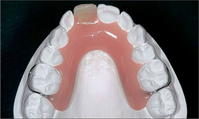
Fig 5 Occlusal view of the maxillary study cast with the simple removable partial denture, which was to serve as an interim restoration after the extraction of tooth 11.
With the tooth to be extracted still in place, the laboratory technician precisely anticipated on the study cast the local site configuration expected after tooth removal. In this process, the tooth was hemisected exactly at the gingival level. A discrete concavity was created at the same site in order to adapt a prefabricated acrylic denture tooth as an ovate pontic. The landmarks provided by the contralateral tooth helped create a simple but esthetically pleasing provisional that did not have a buccal denture flange, as no soft-tissue deficiencies had to be compensated for at this stage of treatment (Fig 6).
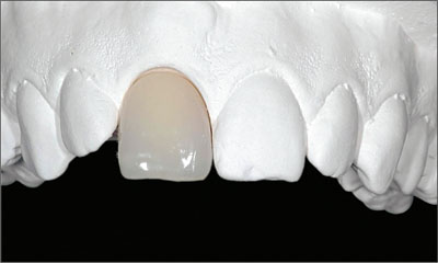
Fig 6 Labial aspect of the provisional removable partial denture (RPD). The laboratory technician had tried to respect, as much as possible, the symmetry-related esthetic parameters gathered from the contralateral site (21). In particular, the cervical aspect of temporary tooth 11 had been designed as an ovate pontic of a conventional fixed partial denture (FPD) without a labial denture flange.
During the second appointment, tooth 11 was carefully and gently extracted without elevating a flap, using small desmotomes. Particular care was taken to avoid any mobilization of the root in a vestibular direction in order to preserve as much of the remaining buccal bone plate as possible (Fig 7).
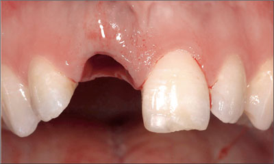
Fig 7 Clinical view immediately after extraction of tooth 11. This procedure was performed without elevating a mucoperiosteal flap.
The presence of an active periapical inflammatory process with associated pain, swelling (Fig 8), and a persisting fistula was incompatible with a more progressive and more rapid approach, such as the immediate placement of an implant.
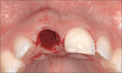
Fig 8 Occlusal view of site 11 immediately after tooth extraction showing the amount and extent of the vestibular soft-tissue swelling due to the active periapical inflammatory process.
Once the infected tooth 11 had been removed, the significant root resorption and abundant presence of granulation tissue fully confirmed the indication for an extraction (Fig 9).
Fig 9 Examination of the extracted root. Mid-facial perforation, periapical root resorption, and abundant inflammatory tissue.
Following the extraction, the previously fabricated provisional RPD was carefully inserted and checked for any excessive soft-tissue contact and compression in order to guarantee uneventful healing. Besides assuring function, phonetics, and esthetics, the objective was to establish slight soft-tissue contact, especially at the interproximal aspects, to provide minimal support to the papillary tissue, preventing excessive collapse towards the center of the extraction site (Fig 10).
Fig 10 Care was taken not to compress the soft tissue at the fresh extraction site with the removable provisional partial denture, while also providing minimal tissue support in the interproximal areas.
Six weeks after the extraction, the soft tissue of the future implant site had uneventfully healed and the respective wound surface was completely epithelialized (Figs 11a, b). As expected, only minimal loss of soft-tissue height at the interproximal aspects and of soft-tissue width in an orofacial direction was observed. The harmonious course of the gingiva could largely be maintained.
Figs 11a, b Vestibular (a) and occlusal (b) views of the extraction site six weeks after the right central maxillary incisor had been removed. Only minimal soft-tissue loss in an orofacial and a coronoapical direction could be observed, and the scalloped course of the gingival was maintained. A marked concavity still existed in the center of the former extraction site.
However, as a distinct concavity at the center of the former extraction site was still present, it was decided to wait for more tissue fill-in and to postpone the planned insertion of the implant for an additional two weeks.
This additional healing time contributed to a more favorable soft-tissue situation from a surgical point of view, eight weeks after the extraction (Figs 12a, b).
Figs 12a, b Eight weeks after the extraction of tooth 11, the soft-tissue situation at the site of implantation was considered adequate according to the preferred early placement/early loading protocol.
At this stage, a periapical radiograph was taken to examine the osseous status at the future implantation site (Fig 13). This two-dimensional diagnostic document confirmed that the vertical bone level at the interproximal aspects of the two neighboring teeth was maintained at a height similar to that before the tooth was removed. As this height corresponded to a physiological distance from the CEJ of the adjacent teeth and as this parameter had been proven to represent a key factor for soft-tissue support around implants, the esthetic prognosis was excellent.
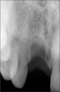
Fig 13 Eight-week post-extraction apical radiograph documenting favorable bone height at the interproximal aspects of the adjacent teeth.
Based on the clinical and radiographic examinations that had confirmed that the optimal situation for early implant placement had been reached, the decision was made to proceed to the surgical phase of the treatment. A slightly palatal crestal incision was chosen and a mucoperiosteal flap with two relieving incisions was elevated. As expected, part of the buccal bone plate was missing, but without affecting the width of the orofacial crest at adjacent teeth further apically (Fig 14).
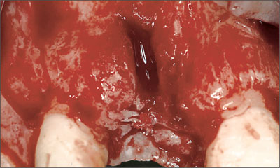
Fig 14 After elevation of a mucoperiosteal flap with mesial and distal relieving incisions, the absence of the buccal bone plate at the center of the prospective implantation site became apparent.
The occlusal view of the site confirmed, as anticipated, the compatibility of the local crestal-bone anatomy with the placement of an implant in combination with a simultaneous guided bone regeneration (GBR) procedure (Fig 15). More specifically, a localized bone defect at the vestibular aspect of the prospective implant site was ob served. This favorable two-wall defect anatomy is fully compatible with the insertion of an implant, as it permits the achievement of (1) primary implant stability; (2) an implant position entirely inside of the alveolar crest confinement; and (3) either a three-wall or a two-wall defect that can be corrected predictably with a simultaneous GBR procedure.
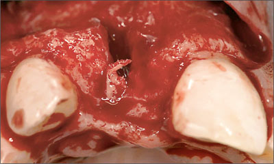
Fig 15 Occlusal view, confirming that only moderate horizontal bone loss had occurred since the extraction.
As documented by Figures 16a and b, an adequate three-dimensional implant position, resulting in a two-wall bony defect at the buccal aspect, was achieved. The entire circumference of the implant body and the implant shoulder were located within the alveolar bone crest (Buser and coworkers, 2004).
Figs 16a, b Labial (a) and occlusal (b) views of site 11 immediately after placement of a Regular Neck (RN) Tapered Effect (TE) implant. Adequate three-dimensional implant position, completely within the alveolar housing and fully compatible with a simultaneous localized GBR procedure.
Once the appropriate three-dimensional implant position had been reached and its primary stability confirmed, the localized GBR procedure was undertaken. It consisted first of the harvesting of autogenous bone grafts (“chips”) in the close vicinity of the implant site and then of an adaptation to the exposed buccal implant surface to fill in the small dehiscence-type defect (Fig 17).
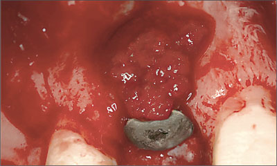
Fig 17 The persisting localized dehiscence-type defect on the labial aspect of the freshly inserted implant was covered with small bone chips harvested next to the implant site.
In order to guarantee an adequate thickness of the buccal bone wall, a substantial layer of bone fillers, soaked in blood, was applied (Fig 18). These bone fillers with a lowsubstitution rate will provide the necessary support and stability for the overlaying soft tissue. As the bone fillers would be resorbed only slowly or not at all, the convex vestibular alveolar-ridge profile achieved strongly resembled that normally observed buccally of natural roots, would be maintainable long term.
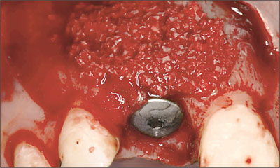
Fig 18 With the application of a substantial layer of bone fillers on the localization of the dehiscence defect, which gradually extended to the periphery, a distinct convexity at site 11 was achieved. This procedure, which included a slight “overbuild” of the vestibular contour of the alveolar bone crest, was intended to provide the required support and long-term stability for the overlaying soft tissue.
As well documented in the literature, a bioabsorbable barrier membrane was applied to avoid a second open-flap procedure to remove the membrane. A so-called “double-layer” technique was used to improve membrane stability. Once soaked with blood, the membranes could easily be adapted to the alveolar-bone crest and did not require any additional fixation (Fig 19). In the esthetic zone, complete soft-tissue coverage of the implant site is most often preferred, in combination with a submerged approach aimed at complete primary wound closure.
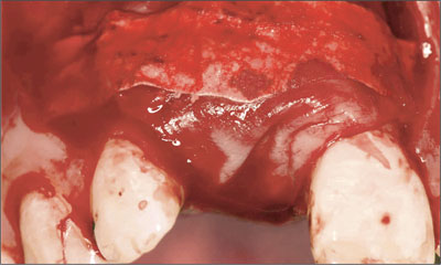
Fig 19 A bioabsorbable barrier membrane was applied in two layers to create the preconditions for a successful GBR-procedure. No additional membrane-fixation measures were necessary.
In order to permit optimal, tension-free flap adaptation in view of a complete primary wound closure (Figs 20a, b), the periosteum was split at the basis of the flap.
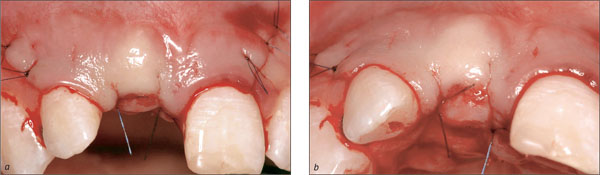
Figs 20a, b Primary wound closure was achieved with incision of the periosteum at the basal level of the flap, compensating for the significant “over-build” of the labial aspect at the implant site.
At the end of the surgical procedure, an apical radiograph was taken to serve as a baseline reference and to document/verify the adequate relationship between the neighboring roots and the intrabony part of the inserted implant (Fig 21).
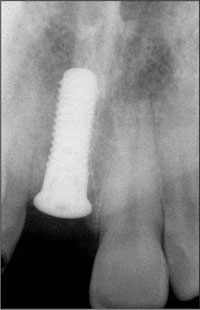
Fig 21 Periapical radiograph, illustrating a satisfactory position of the implant with respect to the different landmarks (CEJ, neighboring roots) provided by the adjacent natural dentition.
The GBR procedure required a significant cervical reduction of the provisional RPD to avoid any excessive tissue compression in the region of the freshly inserted implant (Fig 22).
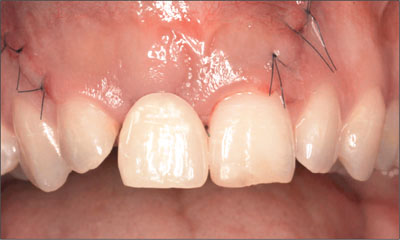
Fig 22 The provisional RPD was shortened at site 11 to minimize the risk of interference with the healing process.
After ten days of uneventful soft-tissue healing, the temporary restoration was relined for the patient’s subjective comfort and to improve the esthetic appearance in the region of the anterior maxilla (Fig 23).
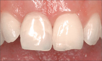
Fig 23 As soon as the process of soft-tissue healing permitted, the temporary RPD was carefully relined to establish optimal tissue contact and to improve the esthetic appearance of the anterior maxilla.
In accordance with an early loading protocol and taking into account the individual extent of GBR performed, the prosthodontic procedure could be initiated in this patient ten weeks after implant placement. At that time, the phase of primary soft-tissue healing was considered completed (Figs 24a, b).
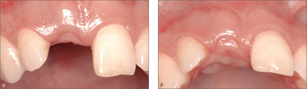
Figs 24a, b Vestibular (a) and occlusal (b) of the implant site after a ten-week period of uneventful healing, documenting that the first phase of post surgical soft-tissue maturation was completed. Only minimal vertical tissue loss had occurred compared with the pre-surgical situation.
A periapical radiograph was taken to confirm a stable peri-implant bone situation (Fig 25). In particular, the interproximal height of the bone surrounding the adjacent natural teeth had been maintained at a level comparable to that before implant placement.
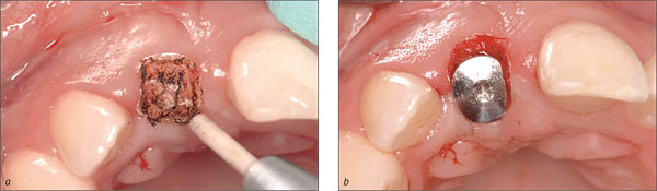
Fig 25 Intraoral radiograph, documenting the anticipated stable peri-implant bone.
The first step of the restorative phase consisted of establishing access from the soft-tissue surface to the underlying implant shoulder. In this patient, a CO2 laser technique (Fig 26a) was used and the short titanium healing cap replaced with a longer one (Fig 26b) in order to maintain the freshly created restorative access.
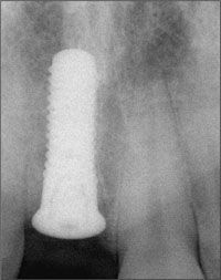
Figs 26a, b A CO2 laser technique was applied to create access to the underlying implant shoulder (a). The original short healing cap was subsequently replaced by a longer one to maintain the newly established restorative access (b).
Ten days later, the peri-implant soft tissue (Fig 27) was considered compatible with impression-taking or the fabrication of a chairside implant-supported provisional restoration.
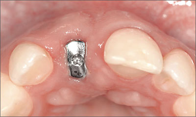
Fig 27 Approximately ten days after the second-stage surgical intervention, the soft tissue allowed proceeding to the next prosthodontic step.
A direct comparison between the labial view with (Fig 28a) and without (Fig 28b) the provisional RPD in place gave rise to the expectation that the slight excess in soft-tissue height at site 11 would be sufficient to ultimately create a restoration emergence profile similar to that of the contralateral tooth (21).
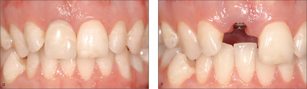
Figs 28a, b Comparison of the labial views with (a) and without (b) the provisional RPD, indicating that sufficient soft-tissue height was present at site 11 to create a symmetrical soft-tissue contour at the position of the two central maxillary incisors.
It was decided to proceed to the fabrication of a direct fixed implant-supported provisional in an attempt to establish optimal peri-implant soft-tissue contours prior to the implant impression. For the fabrication of the planned chairside provisional, a newly developed restorative component, the Regular Neck (RN) synOcta temporary mesoabutment, was used (Fig 29). It is possible to add acrylic resin directly to this substructure, fabricating a one-piece screw-retained implant provisional. The same component can also be used as a mesostructure, serving as a base for a cemented provisional restoration. This component could also be utilized — after substantial occlusal reduction — as a screw-retained tissue conditioner/healing abutment. Under these circumstances, a patient would continue to wear his or her provisional RPD.
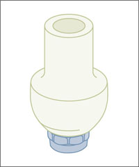
Fig 29 The RN synOcta temporary meso-abutment was used for chairside fabrication of an occlusally screw-retained temporary implant-supported crown. As the marginal area is prefabricated, the clinician only needed to adapt the cervical emergence profile (subtractively or additively) to the requirements of the clinical situation.
The component described could subsequently be attached to a corresponding implant analog, facilitating the finishing procedures that were performed extraorally (Fig 30a). A special holder (Fig 30b) is available for the fixation of the analog.
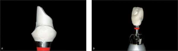
Figs 30a, b In this case, with the implant axis fully compatible with occlusal screw retention, it was decided to connect the provisional crown directly to the implant. As the cervical part of the component is prefabricated and has an excellent marginal fit by definition, a significant number of the fabrication steps can be performed extraorally.
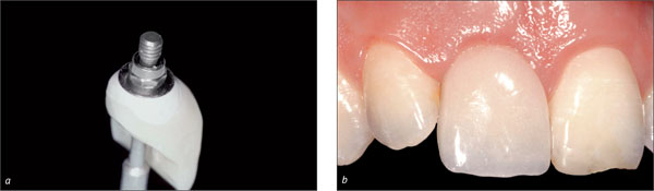
Figs 31a, b After finishing and polishing, the temporary crown (a) produced at chairside was ready for insertion (b).
The RN synOcta temporary mesoabutment can also be used as a base for a screw-retained provisional crown fabricated on a working cast in the dental laboratory (Figs 32a, b).
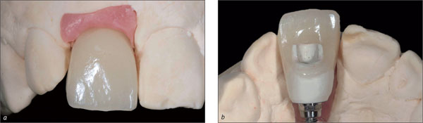
Figs 32a, b For demonstration purposes, a screw-retained provisional crown was fabricated in the dental laboratory, using the previously described RN synOcta temporary mesoabutment as its base.
Two months after the insertion of the fixed temporary implant restoration, the peri-implant soft-tissue contours were judged to be adequate, so that the clinical situation was ripe for taking the final impression. As the implant shoulder was located distinctly submucosally, particularly at the mesial and distal aspects, an approach involving a screw-retained impression cap and an open tray was preferred (Fig 33).
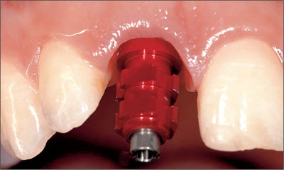
Fig 33 The impression cap was attached to the implant and secured with the matching occlusal screw. The peri-implant soft-tissue contours were satisfactory
A stone working model was produced to fabricate an occlusally screw-retained permanent implant-supported crown (Figs 34a, b).
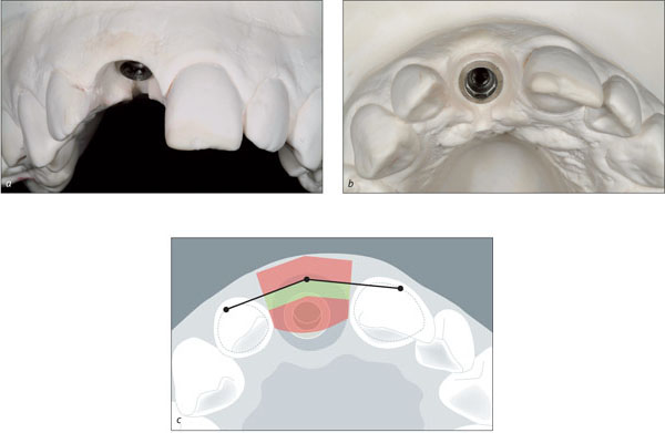
Figs 34a-c Vestibular (a) and occlusal (b) views of the master cast, showing a satisfactory three-dimensional implant position and peri-implant soft-tissue contours optimized on the working cast by the laboratory technician. An access slot was created at the palatal aspect for better visual control of the margin and for ease of manipulation. The implant is ideally placed within the orofacial and mesiodistal comfort zones (c).
The master cast was reproduced in a special dental stone that provided the strong optical contrast necessary for the scanning process essential to Straumann CARES, the Computer Aided REstoration Service (Fig 35).
Fig 35 Labial view of the working cast with the increased optical contrast required for the CARES system during the scanning process.
The so-called scanbody, a prefabricated system component with three well-defined domes at its occlusal aspect, was attached to the implant analog at site 11 by simple finger pressure (Figs 36a, b). The master cast was thus ready to be inserted into the InEos scanner (Sirona) for automatic digitizing of the precise three-dimensional implant shoulder position.
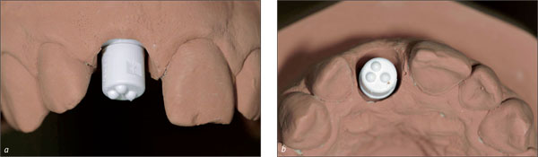
Figs 36a, b Labial and occlusal close-up views of implant site 11 after attachment of the scanbody with its three small occlusal domes, permitting precise three-dimensional scanning of the implant shoulder position.
After the scanning process, the three-dimensional outline of an optimal all-ceramic (ZrO2) CARES custom abutment was designed on the computer screen and milled by the respective computer-assisted manufacturing (CAM) unit. This ceramic custom abutment (Fig 37a) connected to a synOcta 1.5 abutment and allowed for direct veneering with adapted feldspathic ceramics (Fig 37b).
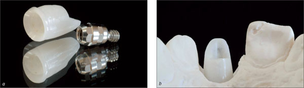
Figs 37a, b The computer-generated zirconium-dioxide custom abutment, to be connected to the synOcta 1.5 abutment (a) and displaying a slightly “whitish” appearance (b), required some preliminary modification to create optimal conditions for esthetic ceramic veneering.
Although the zirconium-dioxide custom abutment featured a certain degree of translucency, its slightly “whitish” appearance (Fig 38a) made a minor preliminary color modification necessary, creating a more dentine-like appearance (Fig 38b) and facilitating the subsequent esthetic veneering (Andersson and coworkers, 2001).
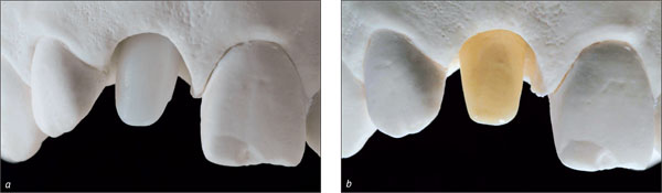
Figs 38a, b The original milled zirconium-dioxide custom abutment displayed a slightly “whitish” appearance (a). Therefore, a first layer of a more dentine-like ceramic material was applied (b) to create an appropriate base for the subsequent layers of ceramic veneering.
Despite the addition of this dentine-like ceramic layer, a significant degree of translucency could be maintained, which was verified by light transmission (Fig 39).
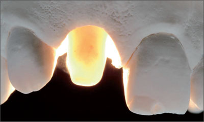
Fig 39 After adding a thin layer of dentine-like ceramic, the remaining translucency of the ZrO2 custom abutment was verified under light-transmission conditions.
In the dental laboratory, the ceramist had the demanding task of duplicating as closely as possible the optical properties of the natural left maxillary central incisor (contralateral tooth) by applying a complex layering technique and anticipating the significant volume contraction associated with the subsequent sintering process (Figs 40a, b).
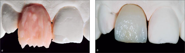
Figs 40a, b In the first step, the clinical crown volume, composed of a complex sequence of layers of different opacities and shades, imitating the basic components—dentine, enamel, and incisal translucency—of a natural maxillary incisor, was established (a). After the first ceramic sintering, a significant volume contraction was observed, requiring at least one additional corrective step. The basic optical properties, however, were already clearly discernible.
Minute layers of more translucent ceramic material were added where necessary to compensate for the contraction that had occurred after the first sintering process (Fig 41a). After this second sintering process, followed by some final adjustments with rotary instruments, the implant-supported crown was ready for the clinical try-in (Fig 41b).
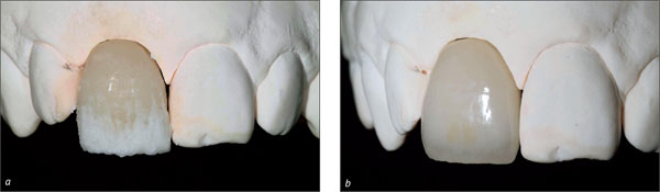
Figs 41a, b Precise addition of more translucent ceramic to compensate for the contraction after the first sintering and to integrate additional optical features from the contralateral natural tooth (a). After the second sintering process, some minor finishing with rotary instruments was performed before the subsequent clinical try-in (b).
A clinical try-in of the ceramic implant-supported crown in its “biscuit stage” was needed to identify, by comparing the natural tooth and the ceramic crown, the optical and esthetic key parameters, such as interproximal ridges, mesial and distal transition line angles, and surface characteristics (Fig 42).
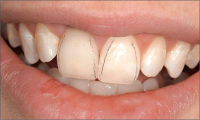
Fig 42 The first clinical try-in of the all-ceramic implant-supported crown 11 revealed an acceptable integration into its natural surroundings and confirmed that the basic features of tooth and tooth volume and the localization of the mesial and distal transition line angles had closely duplicated those of contralateral natural tooth.
In the dental laboratory, the final modifications, focusing primarily on the surface texture characteristics as seen in the contralateral natural tooth, were carried out (Figs 43a, b)
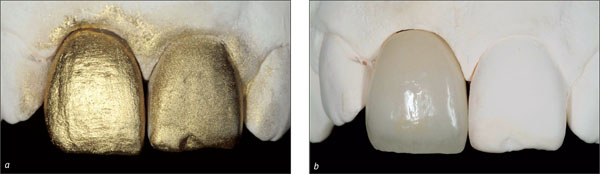
Figs 43a, b The labial surfaces of the implant-supported crown 11 and its contralateral natural tooth 21 were covered with a thin pellicle of gold spray to better highlight the basic features of tooth form and surface texture (a). This facilitated the last finishing steps, mainly carried out by rotary instruments (b).
At this stage, the existing composite restoration at the mesioincisal angle of tooth 21 was replaced (Fig 44). The final all-ceramic crown was inserted and its occlusal screw tightened to 15 Ncm (Fig 45), and the screw-access channel was closed with composite resin.
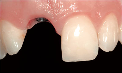
Fig 44 Labial view of the anterior maxilla after replacing the existing mesioincisal composite restoration.
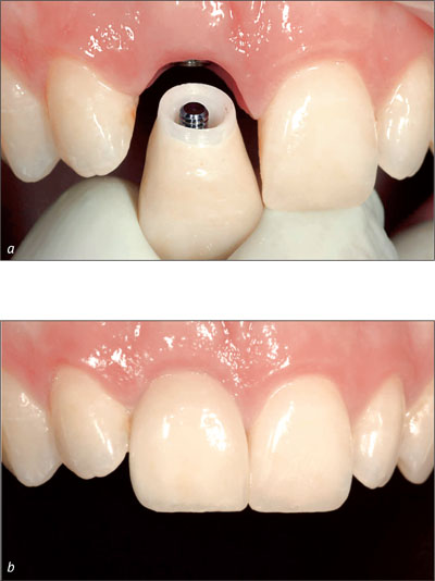
Figs 45a, b The all-ceramic implant-supported crown 11 was inserted (a) and its esthetic integration verified (b).
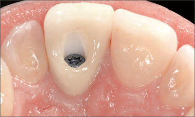
Fig 46 Palatal view of the newly inserted all ceramic implant-supported crown, showing that despite the considerable height and volume of this restoration type, a satisfactory contour was achieved compared to the adjacent dentition.
The radiographic control confirmed stable bony peri-implant conditions, excellent radio-opacity of the zirconium-dioxide custom abutment, and adequate marginal adaptation of the all-ceramic implant-supported crown (Fig 47).
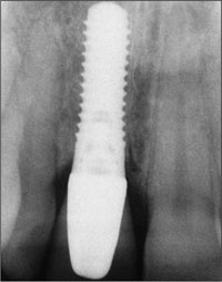
Fig 47 The final radiograph confirmed stable peri-implant bone conditions, excellent radio-opacity of the ZrO2 substructure, and a good marginal fit of the all-ceramic implant-supported crown.
The patient’s unforced smile at the end of treatment documented that the implant-supported crown blended in nicely with the surrounding natural dentition, matching quite satisfactorily the adjacent natural teeth in shape, texture, and color. Furthermore, the line of the marginal gingiva and the line of the incisal edges in relation to the border of the lower lip were harmonious (Fig 48).
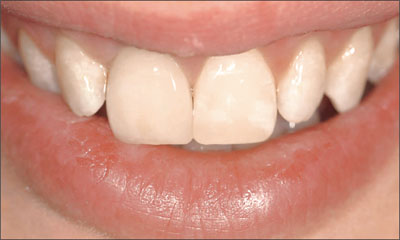
Fig 48 Clinical appearance of the anterior maxillary dentition (patient’s unforced smile).
For demonstration and direct comparison purposes, a second crown was produced for implant 11 based on a CARES titanium custom abutment directly connected to the underlying implant (Figs 49-52).
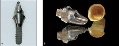
Figs 49a, b For direct comparison, an additional CARES titanium custom abutment (a) was produced for this same implant, serving as a base for a cemented Auro-Galvano ceramo-metal crown (b).
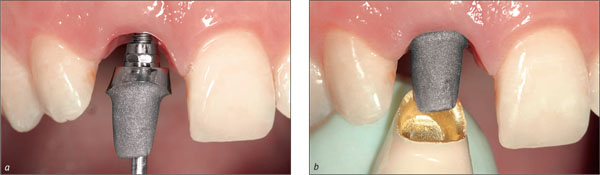
Figs 50a, b The computer-generated titanium custom abutment, which had been previously sandblasted at the future abutment-to-crown interface, was connected directly to implant 11 and subsequently tightened to 35 Ncm (a). The cemented ceramo-metal crown was then tried in (b).
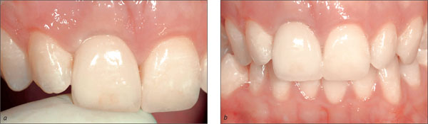
Fig 51a, b The implant-supported crown was held in place with light finger pressure, which led to a discrete blanching of the labial peri-implant mucosa (a). Although still largely acceptable from an esthetic point of view, this second ceramo-metal crown — in contrast to the all-ceramic crown presented previously — showed a slight “grayish” shadow along the labial soft-tissue margin (b). This optical phenomenon was probably due to a decrease in light transmission caused by the metal framework.
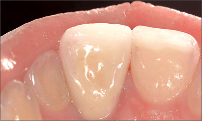
Fig 52 The palatal view, however, demonstrated the more favorable cervical configuration of this type of implant-supported crown, which does not require a screw-access channel.
Acknowledgments
Surgical Procedures
Dr. Daniel Buser – Professor, University of Bern, Switzerland, Department of Oral Surgery and Stomatology
Laboratory Procedures
Master Dental Technician Dominique Vinci, University of Geneva, Switzerland
4.6 Replacement of an Upper Right Central Incisor with a Regular Neck Implant, Restored with an All-Ceramic Crown, Cemented
R. Jung
The 54-year-old male patient, a non-smoker, had ceramo-metal crowns on teeth 11 and 12 that no longer met his esthetic needs (Fig 1). The patient was free of pain. His medical history was without significant findings, and the patient was in good general health.
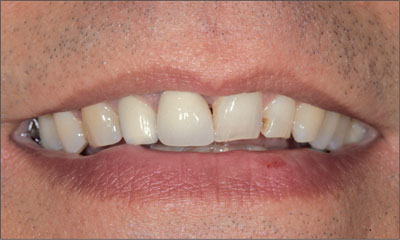
Fig 1 At medium smile, the patient displayed at least three-quarters of his incisors. The incisal edges were unharmonious.
The patient’s wish was to improve the esthetics of his anterior teeth.
At full smile, the patient presented a medium to high lip line, displaying the full crowns and the marginal gingiva (Fig 1).
The harmony of the gingival margin was disrupted by the now rejected ceramo-metal crowns on teeth 11 and 12. The crowns differed from the respective contralateral teeth in shape, texture, and color (Fig 2).
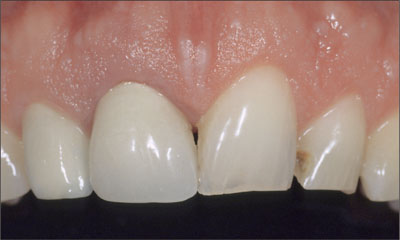
Fig 2 Buccal view of the incisors revealing a thick-tissue biotype with soft-tissue excess to the buccal gingival margin of tooth 11.
The patient’s gingival biotype was thick, with a broad band of attached keratinized gingiva and a moderate (medium) scallop height.
The soft tissues were free of recessions (Fig 2). The patient’s soft-tissue situation was favorable due to the slight soft-tissue excess at the buccal gingival margin of tooth 11 compared to that of tooth 21.
The patient’s crown shape was mostly triangular. The more the crown shape tends towards the triangular, the higher the esthetic risk. In this patient, however, the esthetic risk was reduced thanks to the contact area that was present at the mesial aspect of tooth 21. Furthermore, the incisal edges of the contralateral teeth differed in height. Teeth 11 and 12 appeared to be longer than the respective contralateral teeth. The option to shorten the incisal portion of a tooth reduces the esthetic risk of obtaining a long clinical crown after implant reconstruction.
The incisal view shows a harmoniously contoured arch without any horizontal deficiencies (Fig 3).
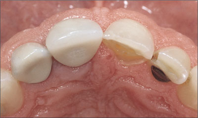
Fig 3 Occlusal view of the incisors. Favorable buccal contour.
A loose crown on tooth 11 was detected at the clinical examination. Further, the pre-treatment periapical radiograph revealed a root-canal filling and secondary caries at tooth 11, which was also fractured in the coronal part of its root (Fig 4).
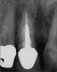
Fig 4 Periapical radiograph showing a root-canal filled tooth with a post and a gap between the crown and the root. The periapical area seemed to have no pathology, and the interproximal bone level of the adjacent teeth seemed to be intact.
Radiologically, the interproximal bone-crest levels of the adjacent teeth seemed to be sufficiently well maintained to allow for a distance of about 5 mm between them and the contact points of the future crowns (Fig 5).
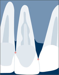
Fig 5 Interproximal bone-crest levels of the adjacent teeth allowing the “5-mm rule” to be observed.
If the distance between the interproximal bone crest and the contact point exceeds 5 mm, the papilla may not fill the interdental space, and a “black triangle” is likely to result (Tarnow and coworkers, 1992; Choquet and coworkers, 2001).
Periodontal probing revealed a probing depth of 6 mm at the buccal aspect of tooth 11. This might be explained by the superficial fracture of the buccal root. Mesially, the probing depth exceeded 5 mm; more tissue could have been lost during therapy, a fact that needed to be taken into account. The patient needed to be informed about this clinical finding and its potential influence on the esthetic treatment outcome, as it created an esthetic risk.
The gingival margin of contralateral tooth 21 was located about 1.5 mm further apically than that of tooth 11. This “soft-tissue excess” around tooth 11 in combination with the medium-scalloped, thick-tissue biotype were important prerequisites for immediate implant placement and transmucosal healing.
After immediate implant placement, unpredictable remodeling processes at the hard-tissue and soft-tissue level had to be expected (Botticelli and coworkers, 2004). Favorable conditions as in this patient (Fig 6) will tolerate a certain amount of soft-tissue recession without compromising the esthetic treatment outcome.
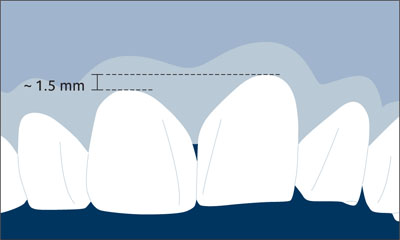
Fig 6 Soft-tissue excess at the future implant site minimizing the risk of a compromised esthetic treatment outcome with regard to the height of the future peri-implant mucosa.
The above clinical and radiological findings are the basis for the patient’s esthetic risk profile (Table 1):
| Esthetic Risk Factors | Low | Medium | High |
| Medical status | Healthy, cooperative patient with intact immune system | Reduced immune system | |
| Smoking habit | Non-smoker | Light smoker (< 10 cig/d) | Heavy smoker (> 10 cig/d) |
| Patient’s esthetic expectations | Low | Medium | High |
| Lip line | Low | Medium | High |
| Gingival biotype | Low scalloped, thick | Medium scalloped, medium thick | High scalloped, thin |
| Shape of tooth crowns | Rectangular | Triangular | |
| Infection at implant site | None | Chronic | Acute |
| Bone level at adjacent teeth | ≤ 5 mm to contact point | 5.5 to 6.5 mm to contact point | ≥ 7 mm to contact point |
| Restorative status of neighboring teeth | Virgin | Restored | |
| Width of edentulous span | 1 tooth (≥ 7 mm) | 1 tooth (< 7 mm) | 2 teeth or more |
| Soft-tissue anatomy | Intact soft tissue | Soft-tissue defects | |
| Bone anatomy of alveolar crest | Alveolar crest without bone deficiency | Horizontal bone deficiency | Vertical bone deficiency |
The esthetic risk-profile analysis shows a medium esthetic risk for this patient.
Based on the above analysis, it was decided to extract tooth 11 in a minimally invasive mode and to perform immediate implant placement (type 1) with transmucosal implant healing, using a Standard Plus implant with an endosseous diameter of 4.1 mm and a Regular Neck prosthetic platform of 4.8 mm in diameter and 12 mm in length. Figure 7 shows the pre-implantation treatment planning on the orthopantomograph (OPT).
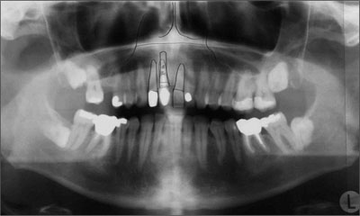
Fig 7 Visualization of preoperative treatment planning by drawing the adjacent roots, the anatomical structures, and the planned implant on a transparent foil on top of the OPT.
For immediate implant placement, it was important to have at least about 3 mm of residual bone height apically of the extraction socket to ensure sufficient primary stability (Fig 7).
Because the root of the extracted tooth 11 was tilted distally the implant bed had to be carefully prepared regarding the mesiodistal aspect of the extraction socket to ensure a correct three-dimensional position of the implant (Figs 10, 11).
In order to ensure optimal access to the implant site and the expected buccal bone deficiency and to keep bone denudation and soft-tissue trauma as minimal as possible, aflap design with one vertical releasing incision at the distal aspect of adjacent tooth 12 was chosen (Fig 8)
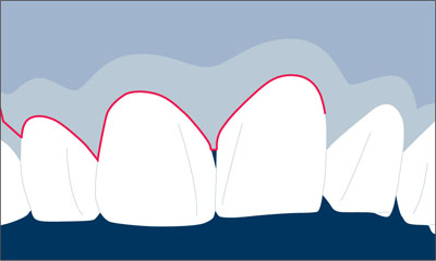
Fig 8 One vertical releasing incision instead of two to reduce trauma and the area of bone denudation.
A TE (Tapered Effect) implant would have been a sound choice as well, but at the time of implantation, the TE implant was not yet com/>
Stay updated, free dental videos. Join our Telegram channel
VIDEdental - Online dental courses


