CHAPTER 28 Diagnosis and Treatment of Complications
CAVEATS
At this juncture, reviewing the section on surgical anatomy in Chapter 4 and all of Chapters 6, 7, 8, and 9 would be useful.
ARMAMENTARIUM
INTRAOPERATIVE COMPLICATIONS
Endosteal Implants
Oversized Osteotomy
Root Forms
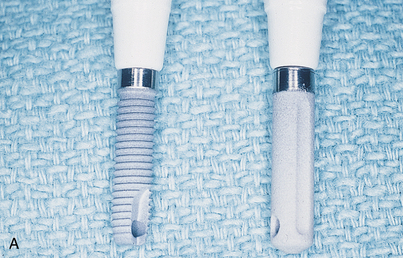
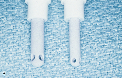
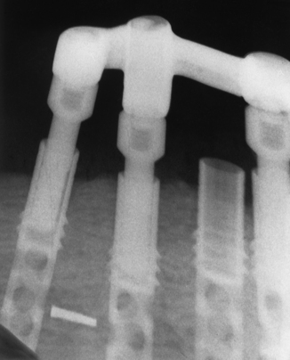
The best way to manage problems is to practice avoidance. Most systems, including Nobel Biocare, Biomet-3i, Zimmer, Straumann, Neoss, and Camlog, offer implants of several diameters. If, during placement of a 3.5-mm diameter implant, the dental surgeon discovers that the endosteal threads have been stripped, a larger diameter implant is placed (if the ridge is 6 to 7 mm wide) that successfully retaps and grasps the internal environment of the osteotomy. Nobel Biocare offers a 4.3-mm implant as a replacement if the surgeon strips the bone while seating the standard 3.5-mm size. The Biomet-3i series is available in 3.25 and 4 mm and in larger diameters. An additional advantage of these implants is that they get wider toward the coronal end. The Camlog series 3.8-mm diameter implant has a threaded 4.3-mm backup size. However, a press-fit 3.8-mm implant also is available, and it can be used as a substitute for the stripped threaded implant site (Fig. 28-1).
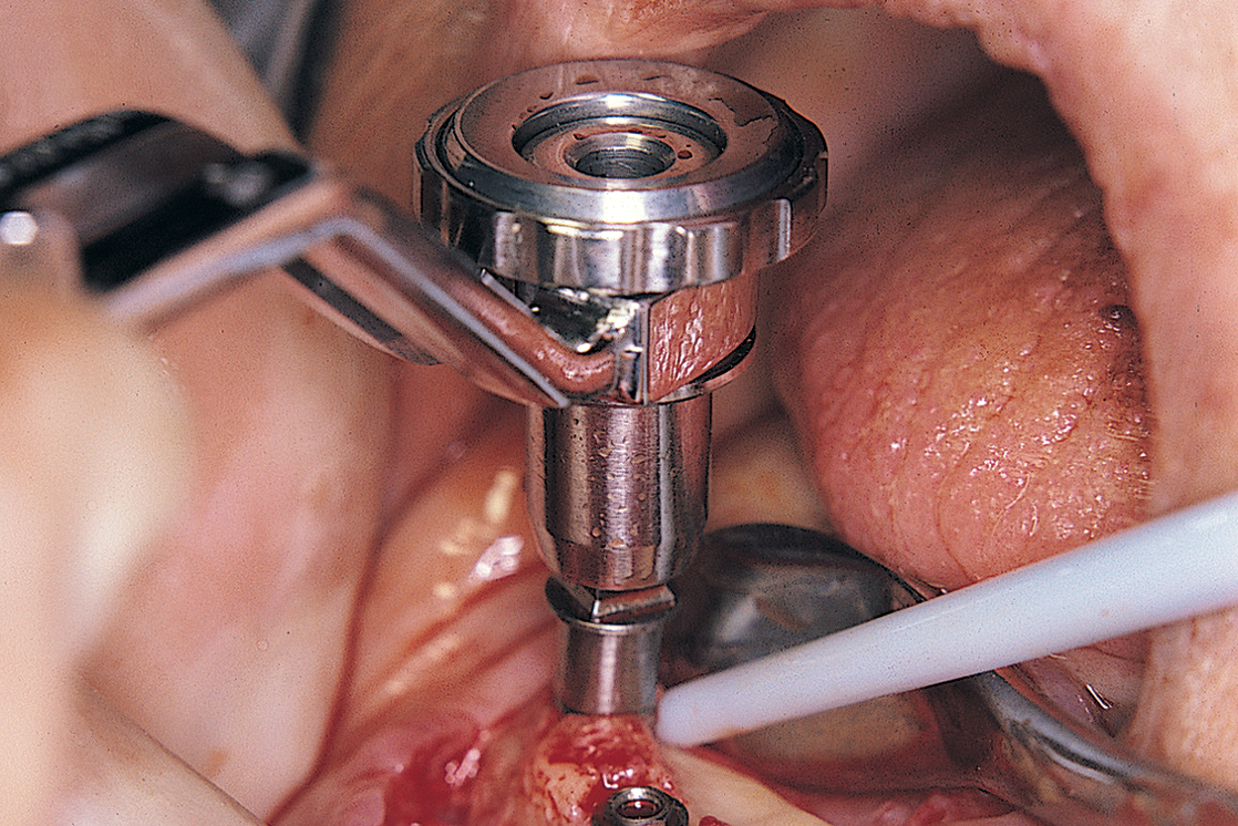
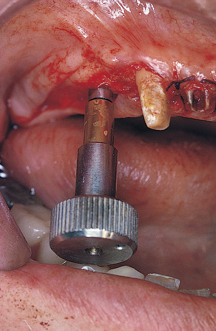
A safer approach is to stop the motor at a point four or five rotations from final seating and complete the procedure with the handheld ratchet wrench (Fig. 28-2). The wrench is held near its working end to neutralize the great leverage of its long handle. This leverage, if not governed carefully, may be responsible for stripping the internal bony threads. The preliminary efforts at placement are made by attempting to turn the implant with the wheel only (Fig. 28-3). If after all these precautions, the implant does not come to a final and firm stop, it should be removed, and the next-larger diameter implant should be inserted, placed without the formality of bone-tapping or threading devices. Practice and experience help flatten the learning curve.
If the osteotomy becomes oversized during insertion of a press-fit or threaded implant from a system without an available larger diameter, the implant should be removed, and some 250-to 500-μm tricalcium phosphate (TCP), particulate HA graft material should be placed against the internal walls of the osteotomy. The implant should be moistened with blood or saline and rolled in the particulate slurry until a thin layer of the slurry clings to it. The implant then is reinserted to achieve a frictional fit. Coverage of the osteotomy site with a guided tissue regenerative membrane (GTRM) can improve the chances of successful osseointegration. A maximum space of 0.5 mm is allowable for this technique (Fig. 28-4).
Blade and Plate Form Implants
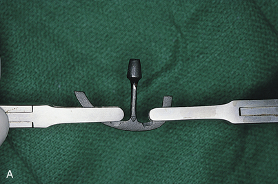
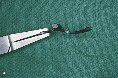
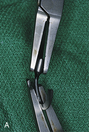
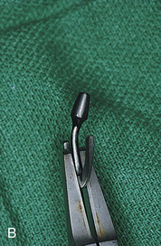
The following suggestions are suitable for one-piece and submergible blades. If the osteotomy is larger than the blade infrastructure, a second Omni or Ultronics blade (these are supplied in “blank” form) should be trimmed longer or deeper to create a frictional fit in the bone slot (if anatomic structures permit). With all non-HA-coated blades, both custom and catalog, primary retention is achieved by bending the infrastructure into a gently curved S pattern. This provides a primary frictional fit by locking the blade into position while the process of osteogenesis takes place. Two titanium-tipped, cone socket pliers are used to bend the blades; very gentle but firm pressure is applied so that the bends are gradual rather than acute (Fig. 28-5).
Perforations of Cortical Plates: Root Form, Plate Form, and Blade Implants
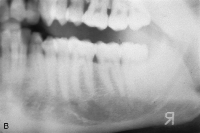
When osteotomies are performed for the seating of endosteal implants, whether laminar, grooved, slotted, or cylindric, a perforation is possible, even if the host site is capacious. The perforation, which can be medial, lateral, or apical, can occur because of misdirection of a drill or because of an unexpected anatomic irregularity (e.g., the submandibular fossa beneath the mylohyoid ridge) (Fig. 28-6).
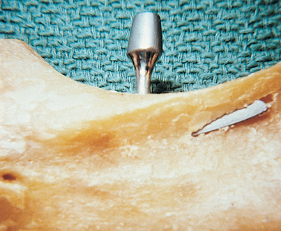
Plate fracture often is difficult or impossible to avoid. It should be left untreated if no displacement occurs. However, the dental surgeon should always test for perforations. After each osteotomy is completed (for all implant types, including endodontic implants), its integrity is tested with a long, thin, blunt probe (e.g., the Kerr Dycal instrument or a 40-mm No. 50 endodontic reamer). If the tip falls through an inaccessible fault or perforation, it would be wise to cover the area with a membrane (see Chapter 8 ), tease a Colla-Plug over it, or gently tap some synthetic or autogenous bone at the base of the defect. The soft tissues are then closed, bone healing occurs for 6 months, and reoperation is performed. If the mandibular canal is involved, a Colla-Plug is placed gently into the base of the defect to avoid forcing graft particles into the neurovascular bundle. If the perforation is in a visible and operable location (e.g., the labial cortex), the implant is allowed to remain in position, and its exposed portion is covered with particulate bone (preferably autogenous), which can be harvested from the tuberosity. The repair is completed by covering the graft with laminar bone (Lambone), and primary closure is performed.
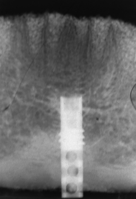
If an unintentional perforation occurs during preparation of an osteotomy beneath the antral floor, but the tip of the drill does not penetrate or injure the sinus membrane, the implant is placed and allowed to extend beyond the cortex for up to 2 mm, thereby “tenting” the sinus lining. If the implant progresses to integration, it remains in successful equilibrium with its environment. If it fails to integrate, the extension into the cavity space (which offered no additional bony retention) poses the threat of formation of an oroantral fistula (Fig. 28-7). An unintentional perforation is managed in a predictable and acceptable manner, as recommended by the Summers technique (see Chapter 8).
Air bubbles leaking from the osteotomy indicate perforation into the maxillary sinus (Fig. 28-8). In these cases, an acceptable remedy is deep repair with a Colla-Plug and graft material, followed by placement of a shorter implant. If this appears to be unsatisfactory, a primary closure is made with a buccal (undermined) pedicle graft (see Chapter 7), the flap is sutured over intact bone, and the sinus regimen in Appendix G is prescribed. If osseointegration takes place, no treatment is necessary. If osseointegration fails to occur and a connective tissue interface results, the possibility of maxillary sinusitis arises. The patient should be told about the implant’s proximity to the antral floor, and the symptoms of sinusitis should be described. If the symptoms occur at a later date, the implant’s status is assessed, and if it is failing, it is removed. The communication between the oral and antral cavities is repaired with either a buccal or palatal pedicle graft. These procedures, as well as nasal antrostomy, the Caldwell-Luc procedure, and antral lavage are described later in this chapter.
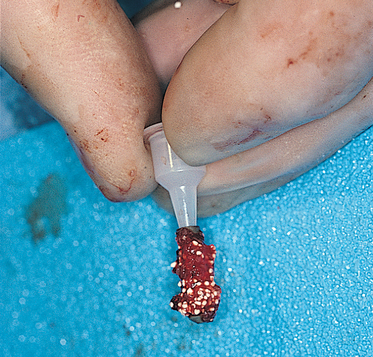
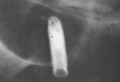
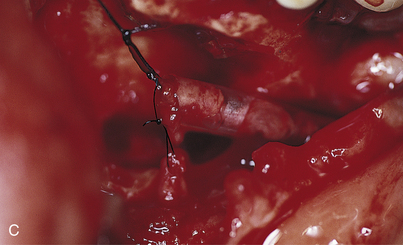
If the canal has been entered, as indicated by inordinate bleeding, the implant should not be placed (Fig. 28-9). Rather, the incision is closed, because the nerve may heal spontaneously. If signs of regeneration (i.e., tingling or formication) do not occur within several months, the patient should be referred to a specialist who performs mandibular neurorrhaphy procedures.
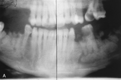
(The discussion of surgical anatomy in Chapter 4 details the possible locations of the mental foramina and the peculiarities of the route taken by their neurovascular bundles.) When implants are to be placed in the region of the mental foramen, this structure is exposed so that its position is localized clearly when the osteotomies are performed. Even with viewing, however, the dental surgeon must bear in mind that the bundle often courses forward, anterior to the foramen, for 4 to 6 mm before curving back to its exit (Fig. 28-10, A). In some cases, two or more mental canals are present (Fig. 28-10, B). If the canal is entered or the nerve is injured, the implant should not be placed. Rather, the wound should be closed in the hope that the dysesthesia will correct with time. If the symptoms persist unchanged for 6 weeks, microsurgical neurorrhaphy should be considered.
If the perforation is through the mandibular inferior border, the surgeon should determine whether the implant can be palpated through the submandibular skin and whether it is sharp. If it is, it may cause chronic injury to the overlying musculature. If degloving through the intraoral route cannot be performed, a small skin incision may be required so that the extended segment of the implant can be trimmed with cooled diamond drills until it becomes level with the inferior border of the mandible. If it is not trimmed, the patient should be informed about the condition and asked to await the first recurrent episode of pain or swelling before taking action (Fig. 28-11).
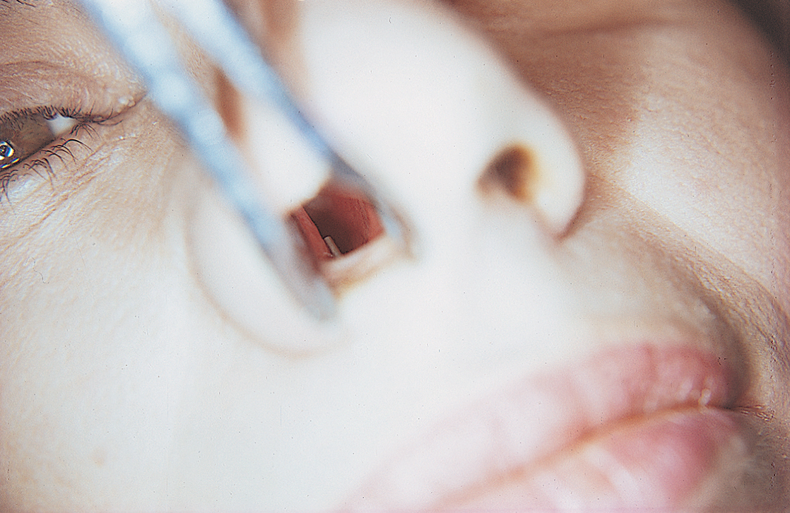
If the perforation occurred through the nasal floor, a speculum with a source of good light is used to inspect the inferior nasal mucosa. If it has been penetrated and the implant can be seen, a method of trimming should be established. This is accomplished intranasally with a diamond drill (Atwood 473) or a pear-shaped bur in a water-cooled, straight handpiece or Impactair. The abraded nasal mucosa heals over the trimmed implant by secondary intention. Trimming also can be accomplished through an intraoral deep anterior vestibular incision. The pyriform aperture is exposed, and the nasal mucosa is elevated with a Freer elevator until the overextended implant can be seen. It is shortened with the same diamond drill. If the nasal mucosa has not been penetrated and the patient does not complain of nasal soreness, the site should be kept under observation until a symptom appears (Fig. 28-12).
Fractured Buccal or Lingual Cortical Plates
Fracture of the buccal or lingual cortical plates can occur with any kind of endosteal implant, but they most frequently happen when the dental surgeon places blades or performs ridge expansion. With this type of fracture, the best choice is to discontinue the implant placement procedure. If the fractured plate appears to be attached to the mucoperiosteal flap, there is a good chance of reattachment and subsequent healing. If the implant achieves firm seating, the procedure might be salvaged with use of a GTRM and bone graft material, precise tailoring and placement of the membrane, and impeccable closure (see Chapter 8).
Inadequate Soft Tissue Flaps for Implant Coverage
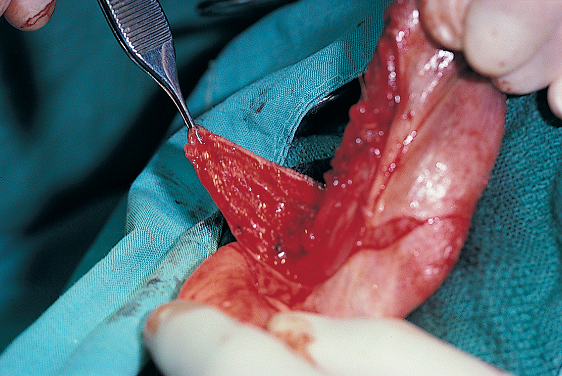
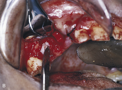
In addition, when implants are placed into a site immediately after tooth extraction or in ridge expansion maneuvers, a scarce amount of the tissue required for primary closure exists. If the implant, whether subperiosteal or endosteal, is bulky enough that the tissues from the facial and lingual sides cannot be brought together, the buccal or facial flap should be undermined. For this technique, a pair of sharp, curved scissors or a Bard-Parker (BP) No. 15 blade is used to elevate the mucosa from the underlying buccinator or orbicularis oris muscle (Fig. 28-13). The mucosal flap is released from its underlying muscle fibers, which allows it to be brought over the implant and ridge crest. Tension-free suturing can then be performed. Closure is done in a continuous horizontal mattress configuration. This technique is outlined in the discussions of suturing in Chapter 6 and of soft tissue management in Chapter 7. Of course, vestibular integrity is lost, and a subsequent vestibuloplasty may be required.
Broken Burs
Burs can break during the pilot osteotomy in preparation for the placement of any type of endosteal implant. This happens most often when the bur (usually a fissure type) binds in bone. Bur fracture can be prevented when binding occurs. Using the thumb and forefinger, the practitioner should grasp the handpiece beneath its head at the point of bur emission and press the fingers together. The bur is pinched between its head and the bone, forcing it vertically upward and out of the bone in a non-torque-influenced movement. Attempts should not be made to remove the bur by wiggling the handpiece shank; this maneuver is the major contributing cause of bur breakage.
When a bur breaks, it usually is deep in the osteotomy and possibly close to a vital structure (Fig. 28-14). Several technique-localizing radiographs should be taken, and then simple probing and suction should be tried. If these fail to dislodge the bur, the patient should be told of its presence, but only after completion of the procedure. The patient should be asked to sign a note acknowledging this information. If the patient is sedated, complete recovery must occur before the person is informed and the signature obtained. Aggressive attempts to remove broken burs or instruments destroy potential host sites and may be responsible for injuries to adjacent vital structures. Burs in noncritical areas can remain safely in place for years. Attempts to remove them should be made only if a local reaction is noted on an x-ray film at some later date.
Hemorrhage
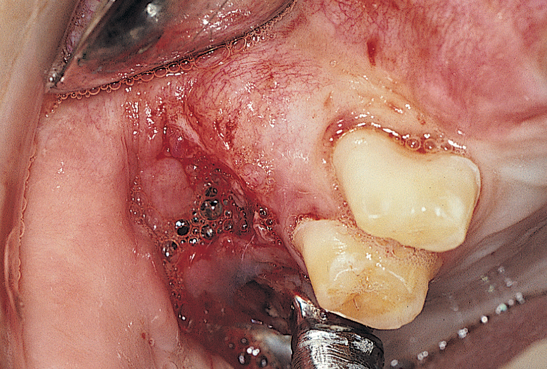
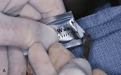
Unusual bleeding may result from soft tissue dissection or intraosseous surgery. If a vessel is bleeding from within the soft tissues, it should be clamped with a fine hemostatic forceps and ligated or electrocoagulated. Often, however, simple tamponade solves such problems (Fig. 28-15). After approximately 5 to 10 minutes of pressure, most small vessels embolize. Firm pressure applied for 5 minutes or longer also usually stops hemorrhage within bone. If not, forcing bone wax into the bleeding site always offers satisfactory results (Fig. 28-16). Gelfoam, Surgicel, and Avitene (spun collagen) also are effective hemostatic agents. Placement of the implant itself into the final prepared hemorrhaging osteotomy often serves as an effective form of management.
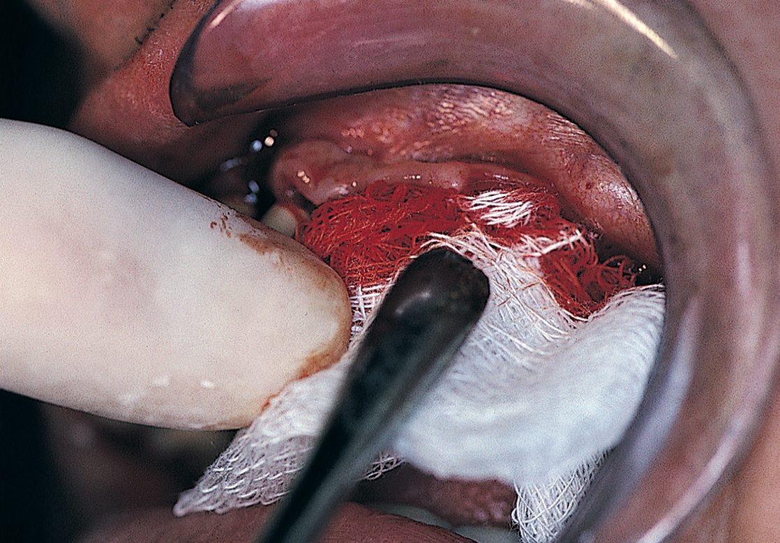
FIGURE 28-15. Continued bleeding can be treated effectively by applying pressure with persistence and patience for at least 5 minutes.
Poor Angulation or Position of an Implant
Blade and Plate Form Implants
Poor angulation or positioning of an implant is rarely a problem if the implant is a one-piece device, because blades are made of flexible, resilient, and compliant metals, and their abutments may be bent into positions of parallelism (Fig. 28-17). Titanium-tipped, cone socket pliers are used to bend the implant so that foreign metals are not deposited on the surfaces of the blade. Submergible blades are treated with friction-fit abutment inserts in the same way when they are inserted. However, the adjustment is made before the implant is seated so that if the abutment fractures and cannot be retrieved from its socket, a new blade can be selected. After the neck is bent to achieve parallelism, the abutment is removed and kept until the second stage, when it can be inserted into the infrastructure socket. Because it has the proper angulation, it can serve as a usable, parallel abutment.
Root Form Implants
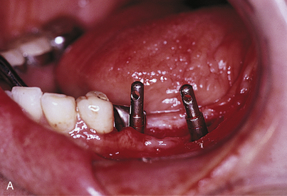
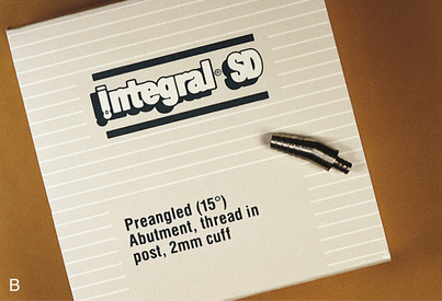
The guidelines for blades can be applied in making angulation corrections for most root forms that have been placed in anatomically unacceptable positions. If press-fit implants with external threading and without antirotational devices (e.g., Spline) are used with angled one-piece abutments, the abutment is inserted into the implant before it is seated. The implant is rotated to a position that makes the abutment parallel to the adjacent teeth and tapped into its osteotomy (Fig. 28-18). The abutment is unscrewed, replaced with a healing screw, and maintained until integration, when it is replaced into the specific implant from which it had been taken.
Another alternative that can be used after integration is to make a direct impression for casting an angled, frictional-fit abutment that would require cementation. Sometimes placement of implants in the most appropriate position in bone (midway between the facial and lingual cortices) causes their abutments to be located too far to the labial or lingual or to emerge from unstable mucosa. If soreness or inflammation results, this problem can be solved with free palatal tissue grafting (see Chapter 7). In addition, angled abutments are available that can be rotated on the implant’s cervical platform; when appropriately positioned in one of a half dozen fixed stops, it is fastened by its fixation screw into the implant’s internal threading receptacle (see Chapter 22).
As outlined in Chapter 4, the nature and dimensions of the patient’s residual bone determines where, at what angle, and the number of root form implants that provide the best prognoses. Because the angulation of the ridge does not always allow ideal implant trajectories, a problem may exist that classic prosthetic procedures cannot solve. The implants may be canted in eccentric directions that would result in the retaining screws emerging from the labial surfaces of the completed prostheses or at other unacceptable sites when fixed-detachable techniques are the choice of reconstruction.
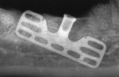
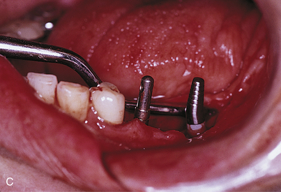
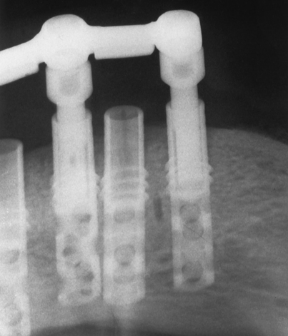
Prevention (i.e., not placing implants if their angulation problem appears to be insoluble), selecting blades or root forms that allow the use of significantly angled abutments, abutments with adjustable necks, angular corrections made with bone-grafting materials, or using subperiosteal implants all are alternatives that help guide operative decisions. Even though accurately made surgical templates should prevent improper placement of implants, occasionally implants are placed too close to one another. The proper distance is a full implant width between each root form (i.e., 3.25 to 5.5 mm). In cases involving closer proximity or poor angulation, the implants should be allowed to remain buried and left unused as “sleepers” (Fig. 28-19).
Injuries to the Mandibular Neurovascular Bundle
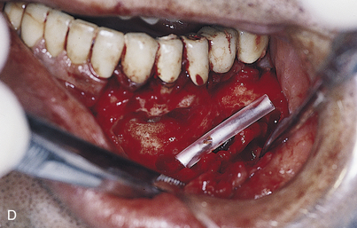
If the dysesthesia has not diminished or changed in depth, nature, or character after 6 weeks, exploration and possible repair should be considered. Although specially skilled oral and maxillofacial surgeons most often perform these procedures, knowledge of this technique is important. If the mental or other soft tissue neurovascular bundle is totally or significantly torn or separated, it should be repaired immediately. The tissues are reflected carefully, already opened, to below the foramen level, exposing the entire nerve complex. The mental neurovascular bundle is moderately resistant to injury, and gentle reflection exposes it fully. The distal portion of the nerve complex is made available, if any of it should be in evidence in the soft tissues lying lateral to the mandible. This gentle, blunt dissection can be easily performed with a mosquito hemostat grasping a moistened, 2 × 2-inch sponge and using a pushing maneuver.
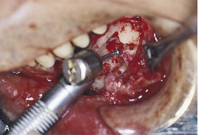
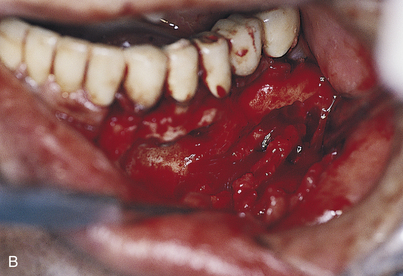
If the proximal bundle offers insufficient length from within the foramen, the periosteum adjacent and posterior to it is elevated to the mandibular inferior border. A small, half-curved, blunted chisel or suitable elevator is inserted into the distal portion of the mental foramen to protect the bundle. A saline-cooled, Impactair or straight air turbine handpiece with a No. 4L round surgical bur then is used to brush the bone from behind the elevator (Fig. 28-20, A). The goal is to extend the mental foramen into the mandibular canal by removing its posterior lateral bony wall. With patience, care, and experience, this can be done with consistency. After 180 degrees of the canal has been removed (Fig. 28-20, B), a nerve hook is slipped beneath the neurovascular bundle so that it can be gently teased from its crypt. Usually, the sheath must be wrested carefully from internal bony spicular attachments.
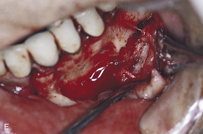
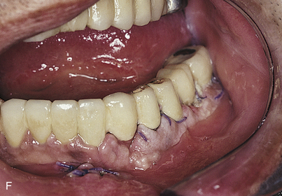
Once the portion of the nerve bundle that occupied the canal has been extricated, it is made contiguous with the mental branch. After the vascular elements are dissected free, a generous additional length is present to facilitate repair of the nerve that had been sectioned or compressed iatrogenically. If 1 cm of distal (tissue) bundle is available and another 2 cm of the proximal portion can be exposed, an end-to-end anastomosis is made with 10-0 Vicryl or Prolene. At least six sutures are required, and four-power magnification must be used to guide their placement. Enclosing the repaired segment in a polyethylene tube (made from a piece of slit IV catheter) offers additional stability and a mortise form to influence unobstructed healing (Fig. 28-20, C to E). The tube and its contents are tucked into the widened canal, and the wound is closed primarily (Fig. 28-20, F). Positive results may not be seen for 18 to 24 months.
If the length is deficient even after exposure of both ends, a sural nerve graft is arranged.
Subperiosteal Implants
Inability to Remove an Impression or Seat a Tray Either for Full Upper (Pterygohamular Design) or Full Lower (Lateral Rami Design) Subperiosteal Implants
Both pterygohamular and lateral rami designs present the possibility of undercuts that can discourage a path of seating or removal. Sectioning the tray into halves or even into three parts for the mandible may solve this problem, with each of the parts fitting its own area of bone accurately (Fig. 28-21). After the tray segments are placed in position and fitted closely, or even allowed to overlap, they are removed. A number of protruding copper tubes or similar retentive devices are processed with heat or luted to their exterior surfaces. Each segment is filled with impression material and reseated. After the impression material has set, an index is taken over the tubes, using additional tray material to engage them. These indices must be removable. After removal of the tray segments, the retention tubes serve as guides for accurate reassembly with the indices. Suturing the wound completes the procedures.
Antral Perforations
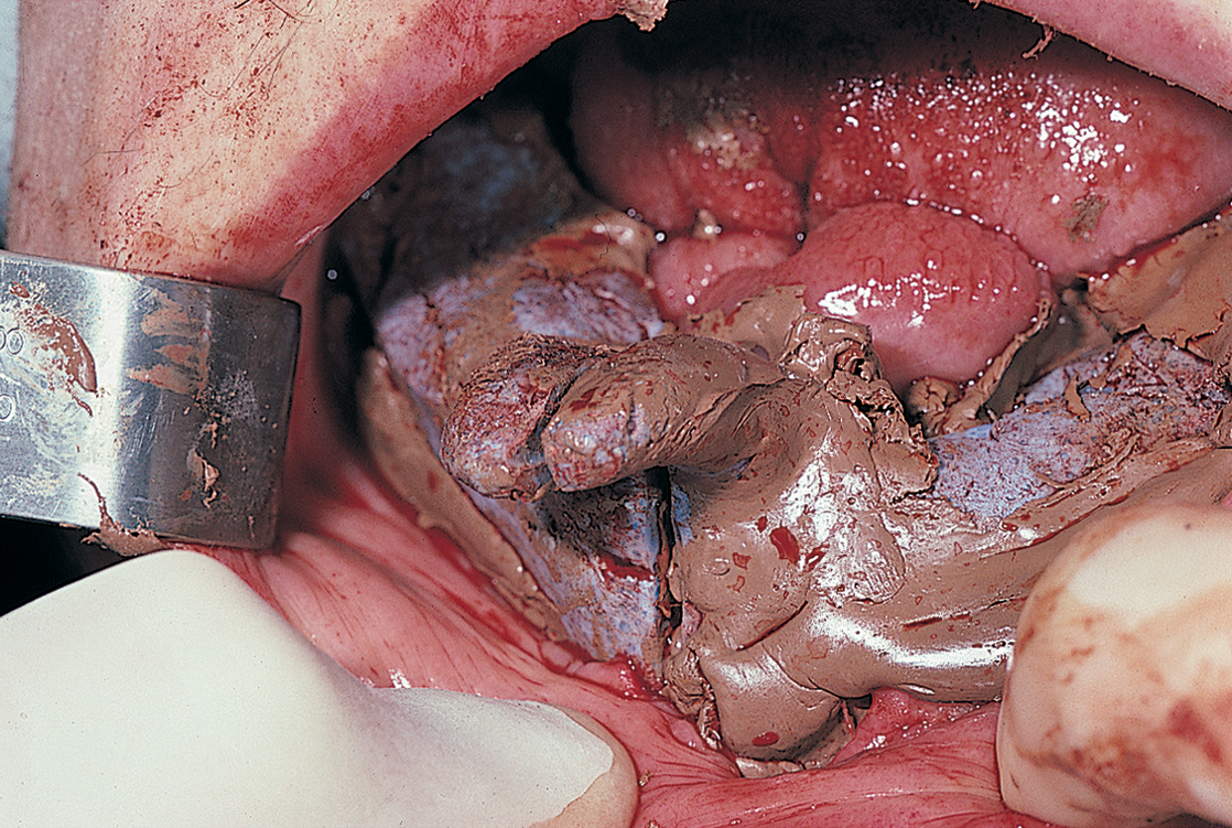
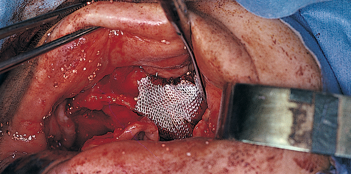
When the mucoperiosteum is reflected in preparation for a maxillary subperiosteal implant impression, some eggshell-thin maxillary cortical bone overlying the sinus may lift away attached to the flap. The intact antral membrane often is noted; it is bluish gray and expands with each expiration. If it is torn, the margins are brought together gently with a nontoothed forceps, and it is covered with a square of Colla-Cote (collagen sheet) or a resorbable membrane (e.g., Surgicel or Vicryl mesh) (Fig. 28-22). The bone fragment is allowed to remain attached to the periosteum.
The implant impression is made in the usual manner, with the Colla-Cote replaced as required at each step. On completion, the flaps are brought together with the cortical bone still in place, and the bone is positioned anatomically and sutured. The bone reattaches over the antrum in its proper location. The final casting design must not include struts placed over the repaired area or over any of the eggshell-type cortex overlying the antrum. If this design characteristic cannot be avoided, a sinus floor elevation and graft procedure is indicated (see Chapter 8). These procedures are performed at the first stage or just before implant placement during stage two.
Stay updated, free dental videos. Join our Telegram channel
VIDEdental - Online dental courses


