Principles for Abutment and Prosthetic Screws and Screw-Retained Components and Prostheses
Carl E. Misch
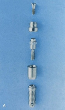
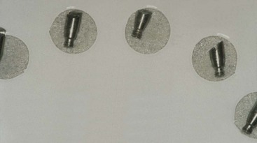
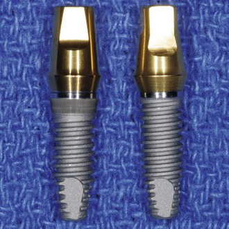
The screw is a simple machine that follows the mechanics of a spiral inclined plane and therefore is highly efficient. It has been used for several centuries in most civilizations. A screw design is the most commonly used implant body to initially fixate an implant into bone and load the bone after hard tissue healing. A screw almost always is also used to connect the abutment components into the implant body. In addition, a screw may be used to fixate the prosthesis into the abutment or directly into the implant body (Figure 28-1).
Abutment and prosthetic screw loosening is one of the most common complications for implant prosthetics. Hence, dentists should have an understanding of implant screw mechanics rather than solely depending on an implant manufacturer to fulfill the needs of the profession. This chapter addresses the primary aspects of screw mechanics for implant components and presents methods to fabricate and handle complications of screw-retained abutments or prostheses.
Screw Retention
Abutment Screws
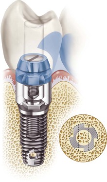
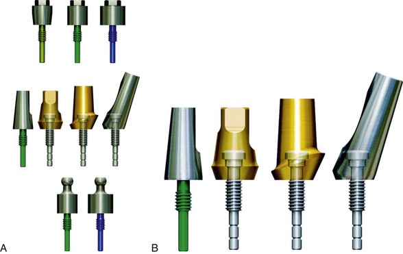
The primary use of screws in implant restorations is to fasten prosthetic components together. In almost all implant systems, a screw is used to fixate the abutment component (i.e., abutment for cement retention, abutment for screw retention and abutment for attachment) to the implant body (Figure 28-2, A). Many years ago, cement retention was frequently used for this purpose but now is not typical for the following reasons:
6. If an abutment fatigue fractures long term, it must be cut out of the implant body. This procedure is difficult and often overheats the implants, leading to bone loss or implant failure. The process may also perforate the thin outer wall of the implant, which usually causes failure (Box 28-1). Therefore, a cemented post rarely is indicated unless all other methods of screw retention have failed, in which case a cemented post then is used as a salvage device.
Several advantages justify the use of a screw-retained abutment component. The abutment screw is the easiest, safest, and most efficient method to fixate prosthetic components to an implant body. The abutment screw provides retention even for small dimensions. The abutment screw is easily retrievable, so transfer impressions may be made. Impression transfer copings may be used to transfer the implant body position to the laboratory. These components must be uncoupled after the transfer is made. In addition, the restoring dentist may decide to exchange one abutment for a slightly different design, angle, or height, so easy insertion and removal is of benefit. Therefore, the readily retrievable aspect of a screw is a significant advantage.
There is also no risk of residual cement at the interface (Box 28-2).
Screw Loosening of Abutment and Prosthetic Screws
Screw retention of the abutment also presents some potential problems. The abutment-to-implant body connection approximates the level of bone and is several millimeters below the margin of the tissue. It may not be completely hermetically sealed and may contribute to bacterial infection, especially when the abutment screw becomes loose.
Chronic screw loosening can be costly and time consuming.1–24 Reports indicate that as many as 6% to 20% of maxillary prosthetic screws loosen at least once during the first year of function.4,25 The coping screw is usually the weakest link in the prosthetic chain. Any discrepancy in occlusion, casting fit, or force may result in vibration during function and screw loosening or breakage where the force is greatest or the metal dimension is weakest. This complication protects the implant body from more severe complications. However, after they occur in a splinted restoration, the other implant abutments are at greater risk of overload and complications than the offending implant because a cantilever and magnification of the load have been created. The amount of increased force varies but may be extreme. For example, moment forces can multiply stress on the crest of the bone-to-implant interface in direct relation to the distance to the next retained abutment. As a result, a 0-moment force can increase to a 250–lb mm moment load with a 25 lb force, although the next abutment is only 10 mm away.
Many conditions that cause prosthetic screw loosening also affect a cement-retained restoration, but the cement seal is often not the weakest link. As a result, unlike the screw-retained restoration, the overload results in complications limited to the region of the higher forces. In addition, the stresses are not magnified by moment of loads created from a partially retained restoration. Increased biomechanical stress during prosthesis fixation can lead to a myriad of complications (i.e., marginal bone loss, implant failure, screw loosening).
The access hole through the occlusal material results in an increased risk of porcelain fracture compared with cement-retained restorations. In a split-mouth study by Nissan et al. of bilateral edentulous sites, ceramic fracture occurred in 38% of screw-retained restorations compared to 4% for cement-retained prostheses.13 The mean loading period for these restorations was 5 years.
The screw-retained prosthesis is not loaded in the long axis, so marginal crestal bone regions have higher stress.2 The occlusal access holes are less esthetic than a cemented prosthesis. Access in the back of the mouth may be limited for the fixation screwdrivers. Progressive bone loading cannot be effectively accomplished because the splinted restorations are not passive.17 The additional cost of analogs and impression transfer components is required for fabrication of the prosthesis (Box 28-3). Most of these disadvantages are addressed in Chapter 26.
After the final abutment is selected and positioned, the restoring dentist does not want the abutment to become loose. Yet abutment screw loosening for fixed prostheses is one of the more common complications, especially for a single-tooth implant. The abutment for cement retention is screwed into the implant body (Figure 28-2, B) Abutment screw loosening is less likely in multiple splinted restorations but also has frequently been reported. Initially in the 1980s, abutment screw loosening was reported to be as high as 65% of the time within a 3-year period.9,14 When the screw is loose, the cemented restoration is different to remove to gain access to the abutment screw. As a consequence, many dentists recommended a screw-retained prosthesis. Since that time, manufacturers have addressed the issue using metal screw mechanics.
Metal Screw Mechanics
The increased risk of prosthetic or abutment screw loosening may be decreased by understanding metal screw mechanics.
The goal of a simple machine is to reduce the effort needed to work. Five systems increase an applied force: (1) screw, (2) incline plane, (3) lever, (4) wheel, and (5) pulley. Of these, the lever and screw are the most important to a restoring dentist. A cantilever is able to magnify a force in relation to the length of the lever (i.e., Mf = F × cantilever length, where Mf is moment force and F is force). A screw is even more efficient as a force magnifier. A 20–N-cm force on a screw is able to move two railroad cars on a flat plane. A screw joint is the term used to describe the connection.
Several factors related to screw design and fabrication can increase or decrease the risk of abutment or prosthetic screw loosening in a metal-to-metal screw system. These primarily are related to preload. In addition, factors that affect abutment screws also include component fit, hex height (or depth), and platform diameter (Box 28-4).
Preload
Preload of an abutment or prosthetic screw is the initial load created by the application of a torque and causes elongation of the screw. Preload places the screw in tension and leads to an overclamping force between the parts of the implant system.26 The aim of tightening a screw using preload stress is to maximize the fatigue life of the screw yet provide satisfactory resistance to loosening. The preload is affected by seven factors: (1) torque magnitude, (2) screw head design, (3) thread design and number, (4) composition of metal, (5) component fit, (6) surface condition, and (7) diameter of the screw (Box 28-5).
Torque Magnitude
The amount of force applied to tighten a screw joint is related to the success of the components staying connected. Torque rotational forces on a screw may be measured in newton-centimeters (N-cm). Too small a torque leads to low clamping forces, which increase the risk of loosening. The clamping forces on a metal-to-metal screw component are one of the more important considerations for long-term screw fixation. The joint strength is improved more by increasing clamp forces than any other condition related directly to the screw. The clamp force is directly proportional to the force used to tighten the screw. The magnitude of the preload is related directly to the clamping force.
The torque applied to a screw component affects both the compressive forces in the threads and the compressive force applied to the head of the screw on the recipient component. The torque applied to the screw also results in tensile forces within the male component of the screw. The compressive and tensile forces from the torque forces are magnified because they are applied to the inclined plane of the screw components (Figure 28-3). The tensile forces attempt to lengthen (strain) the screw when enough torque is applied. The strain (change in length divided by original length) of the screw also is related directly to the amount of torque force. The higher the force, the greater the strain.27 Too great a torque force causes plastic or permanent deformation or a permanent change in the material, at which point the screw is no longer retrievable and additional force causes fracture of the screw. In other words, too large a torque results in fracture of the screw or stripping of the thread components. The suggested amount of the torque for a preload should be 75% of the value to reach permanent deformation of the screw to provide a safety valve for the screw joint.28
The amount of preload applied to a screw joint should be consistent and great enough to cause deformation (strain) within the screw thread. In the original screw retention system of Nobelpharma from 1980 to 1990, only finger forces on a handheld screwdriver were used to tighten screws. A hand screwdriver cannot produce a consistent torque value.29,30 In a study by Misch with 136 dentists, the average torque placed on a screw joint with a hand screwdriver was 11 N-cm and ranged from 5 to 21 N-cm. As a consequence, abutment and screw loosening during that era was observed in almost 50% of the restorations.
In the early 1990s, a torque wrench was used to provide these clamping forces. A torque wrench uses the advantages of a lever to apply the force. The length of the lever of a torque wrench can increase the torque magnitude to more than 100 N-cm of clamping force to the screw, well beyond the elastic limit of the material. Hence, the wrench has a safety valve that limits the torque value to a consistent limit. A torque wrench with high torque stretches the abutment screw. This concept reduced abutment screw loosening to less than 16% during the first year of loading.31
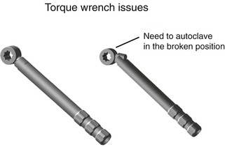
A torque wrench is required to obtain a consistent value of torque. However, several reports have shown that torque wrenches are not completely accurate and components may corrode after autoclaving many times, which may increase the torque applied to the system.29,32,33 Therefore, autoclaving hand torque wrenches in the open position and the doctor testing the torque wrench before use are suggested to make sure the pieces are not frozen in place (Figure 28-4). Periodically, the torque wrench should be recalibrated by the implant company or manufacturer.33
A 30-degree angle, V-shaped screw thread design most often is used for the metal-to-metal connection of an implant system and is called a fixture thread design.34 This 30-degree incline places shear loads on the metal components and permits the metal to be stretched during preload to prevent screw loosening. The amount of torque suggested by most implant manufacturers on abutment screws ranges from 20 to 35 N-cm. However, a wide divergence in optimum torque values applied to screw components has been reported in the literature, ranging from 12.4 to 83.8 N-cm depending on the material and screw design.35,36
It should be noted that because the torque value used during preload is less than the permanent deformation of the screw material, the stretched length of the screw rebounds slightly and reduces the clamping force. As a consequence, it is suggested that the screw is torqued to 75% of its permanent deformation (i.e., 30 N-cm) and then loosened and torqued again. After 10 minutes, the screw is again tightened (it should not be loosened after the second time). This delayed torque method reduces the amount of relapse in the strain of the screw.37
As the screw components work against each other, the wear (settling) slowly lessens the clamp force of the screw to hold together the components. As a consequence, it may be advantageous to periodically tighten a screw after each several-year period, especially in a patient with greater than usual external forces (i.e., parafunction).
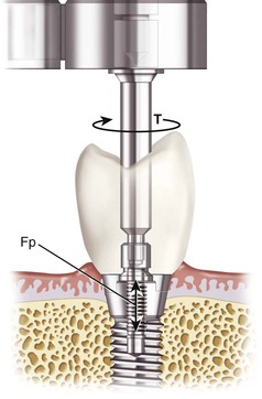
The dentist must take care when placing torque to the screws because torque forces are also transmitted to the bone–implant body interface (Figure 28-5). Bone is 65% weaker to shear forces, and torque places shear forces on the bone. The amount of torque to break the interface of an osseointegrated implant depends on implant design, surface condition, and bone density but may be less than 20 N-cm in soft bone types.38 Therefore, the use of a counter-torque procedure is advocated, especially in soft bone.
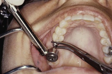
A simple counter-torque method is to use a modified hemostat to hold the abutment while the torque wrench tightens the screw (Figure 28-6). Because the abutment engages the antirotational component of the implant body and the abutment cannot rotate with the hemostat in position, the rotational forces applied to the abutment screw do not transmit to the implant–bone interface.38
To use this counter-torque technique the abutment must engage the hex or antirotational design of the implant. To ensure that the abutment seats completely on the implant body and fully engages the hexagon or antirotational feature of the implant body, a radiograph is often necessary before using the torque wrench when the implant platform is placed below the soft tissue. The counter-torque technique to reduce shear loads to the crestal bone is only effective when the components do not have rotational misfit.
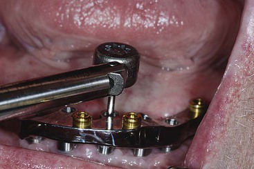
Coping or prosthetic screws that do not engage an antirotational feature on the abutment cannot use a counter-torque technique to prevent torque applied to the implant system (Figure 28-7). This issue is less of a factor when the torque applied to the prosthetic screw is less than the abutment screw (i.e., 10–20 N-cm) and the implants are splinted together. When possible, individual implant crowns with prosthetic frameworks should engage the abutment hex. As a result, the torque applied to the prosthetic screws can be resisted by a counter-torque technique.
Screw Head Design
In an effort to minimize clinical complications, the features of the screw have been enhanced to maximize preload and minimize the loss of input torque to friction. The head of the screw is wider than the outer thread diameter and for an implant abutment or prosthetic screw may be tapered or flat.
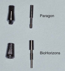
In screw fixation outside of dentistry, a 30- to 45-degree tapered head often is used to help align the individual components that have a misfit during fixation.39 The tapered head acts as an incline plane to align the misfit pieces as the screw is tightened into position. The prosthetic screw was also initially used by Nobelpharma implants in the mid-1980s (see Figure 28-1, A). However, the tapered head prosthetic screw design reduces the clamping effect and reduces the tensile force in the threads of the screw. Most of the force within the tapered screw head is distributed to the head rather than to the fixation screw component. When 20 N-cm of torque force is applied to a tapered head screw, 15 N-cm is distributed to the tapered head incline, and 5 N-cm is applied to the screw threads.
Coping or prosthetic screws designed with tapered (rather than flat) heads should be limited in implant prosthetics28 (Figure 28-8). The tapered screw head distorts and aligns nonpassive frameworks and gives a nonpassive casting the appearance of proper fit. However, the superstructure is not deformed permanently and therefore leads to continued stresses in the system. Even a 10–N-cm torque force applied to an inclined plane of a screw can distort a superstructure and result in significant stress at the crestal bone region.
A flat-head screw is preferred for prosthetic screws. When 20 N-cm of torque force is applied to a flat-head screw, 10 N-cm of clamping force is applied to the screw head, and 10 N-cm is distributed to the screw threads. The increase in torque to the threads increases the strain in the components and decreases the risk of loosening. A flat-head screw also distributes forces more evenly within the threads and the head of the screw and is less likely to distort a nonpassive casting. As a result, the dentist can more easily identify the nonpassive casting40,41 (Figure 28-9).
Thread Design and Number
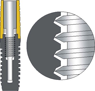
The thread design is also a primary factor influencing the risk of screw loosening. As previously mentioned, the most common abutment screw design used by implant manufacturers is a fixture that is a V-shaped 30-degree angle39 (Figure 28-10). The fixture design allows the preload torque applied to the screw to stretch the male component down the 30-degree angle of the female component of the screw to help fixate the metal components. However, this screw design places almost all of the strain in the first few threads (Figure 28-11, A). As a consequence, when a 30-degree V-shaped thread is used, the number of threads does not need to be more than two times the diameter of the screw.34 As a result, most manufacturers only have a few threads on their abutment or prosthetic screw designs. Because the prosthetic screw has less diameter than an abutment screw, it has fewer threads. The most common abutment screw design is a flat head with five threads and four threads for a prosthetic screw.42
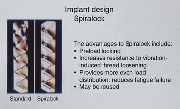
The space industry also uses screws to fixate metal components together. When the space shuttle escapes and enters the earth’s atmosphere, violent shaking of the components occurs. These uneven loading forces can result in screw loosening. For these reasons a different screw design was created by the space industry to distribute the pretorque loads on the screw to each male and female thread component of the screw (Spiralock; Detroit Tool Industries, Madison Heights, MI) (Figure 28-11, B). As a result, the sketching of the screw is more harmonious within each screw thread, and more threads are beneficial and may be added to the system. Additional threads on the screw further increase its resistance to loosening.41,43 This modified Spiralock thread shape was used on the space shuttle to maintain the screw joint integrity.
The Spiralock thread shape has been used exclusively by an implant manufacturer (BioHorizons Dental Systems, Birmingham, AL). The Spiralock implant abutment and prosthetic screws each have eight to 10 threads (Figure 28-12). In a 5-year prospective study, no abutment screw loosening was reported.44 In a multicenter 10-year report for posterior single-tooth replacement, abutment screw loosening occurred in fewer than 1% of the prostheses.45 Elimination of screw loosening is not a consequence of one feature. However, use of improved engineering principles apparently can dramatically decrease the risk of screw loosening.
Metal Composition
The composition of the material is another factor that modifies the performance of the screw. The composition of the metal may influence the amount of strain in the screw from preload and the point of fracture and therefore directly affects the amount of preload that can be safely used. Screw material and yield strength vary greatly when all other factors are similar (12.4 N for a gold screw to 83.8 N for a titanium alloy screw fixation).35,26, A prosthesis screw may exhibit a torsional ductile fracture at 16.5 N-cm versus 40 N-cm, depending on the material from which it is fabricated.34
The plastic deformation or permanent distortion of the screw is the end point of the elastic modulus. Titanium alloy has four times the bending fracture resistance of grade 1 titanium. Therefore, abutment screws made of grade 1 titanium deform and fracture more easily than the alloy. Titanium alloy is 2.4 times stronger than grade 4 titanium. As such, a higher torque magnitude can be used on the titanium alloy abutment screw and female component (found within the implant body), less on grade 4 titanium, less on grade 1 titanium, and the least on gold screws.
The elongation of metal is related to the modulus of elasticity, which depends on the type of material, its width, its design, and the amount of stress applied. The material of which the screw is made (e.g., titanium alloy, titanium, or gold) has a specific modulus of elasticity. A prosthetic gold screw exhibits greater elongation than a screw made of titanium alloy (but a lower yield strength).
Although the strengths of different titanium grades are dramatically different, the modulus of elasticity is similar for grade 1 to 4 titanium. Hence, the strain of the abutment screw is similar with each grade of titanium, but the safety load relative to fracture is different. Titanium alloy (grade 5) has a slightly higher modulus of elasticity. Although not clinically relevant to metal–bone osseointegration, the titanium alloy screw should use a slightly higher preload value. This is not a consequence relative to permanent deformation or fracture because it is more than twice as strong as the other grades of titanium.
The metal is also important to consider for the screwdriver used in the torque wrench. Stripping of the screw head prevents the clinician from tightening or removing the screw. Some manufacturers make the torque wrench driver titanium alloy, and the screw is made of gold or titanium. The concept is that the torque wrench will not deform the hexagon and will not strip, so the device lasts longer. However, this is not ideal. It is easier to replace the torque wrench driver than the abutment or prosthetic screw. Hence, the torque wrench should be made of titanium and the screw of titanium alloy.
From a clinical standpoint, the receptor site for the torque wrench is also a feature of the screw head to consider. The screw head has a rotation feature, usually a straight slot or a hexagon design. The more sides to the rotation feature, the more often the head will strip. Hence, a slot or triangular feature will strip less than a hexagon.
Surface Condition
The surface condition of the screw is a controversial issue in screw mechanics. One school of thought thinks that a rougher surface condition enhances the resistance (friction) in the screw joint and minimizes the risk of loosening. However, those who advocate use of friction-reducing coatings claim that the gain in preload strain is an effective way to enhance fixation. Tests on rough and smooth screws indicate that there may not be any statistical difference at the dimensions of an abutment or prosthetic screw.39,46
Screw Diameter
The diameter of the screw may affect the amount of preload applied to the system before deformation. The greater the diameter, the higher the preload that may be applied and the greater the clamping force on the screw joint.39 Most abutment screws of different implant manufacturers are of similar size. However, the coping and prosthetic screws of many companies are smaller in diameter (and may be a different material). The strength of the material is related to the radius times the fourth power. In other words, a screw half the diameter is 16 times weaker. As a result, abutment screws loosen less often because they can take a higher preload compared with coping and prosthetic screws. Some companies offer similar diameters for abutment and prosthetic screws. As a result, a similar clamping force may be used for either component.
Abutment Screw Connection
The factors of external forces and conditions that affect preload apply to both abutment and prosthetic screws. In addition, some features found in abutment screw connections can increase or decrease screw-related complications.
Component Fit
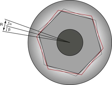
Not all implant manufacturers have the same range of component misfit. In the science of machining metal components, there is a range of dimensions manufactured. In other words, a 4-mm-diameter implant is really a range between 3.99 mm and 4.01 mm. Likewise, the abutment and prosthetic coping connection also has a range. As a result, if a smaller implant body hex dimension is mated with a larger abutment connection, the components may not ideally fit together. Most implant companies allow a misfit range, which results in the abutment or coping being able to rotate ±10 degrees on the implant body. Misfit of abutment components between the abutment and implant body may have a misfit of 10 degrees in a rotational dimension, and horizontal discrepancies have been reported up to 99 microns.47–50 These ranges are different with each implant system. The machining tolerance of a few systems may be as small as 5 microns and less than 1 degree in rotation. The more accurate the component fit, the less force applied to the abutment or prosthetic screw (Figure 28-13).
The incidence of screw loosening is also a function of the accuracy of fit of the flat-to-flat connection of the implant and abutment or prosthetic component. Implant abutment connections or prosthetic connections with an unstable mating interface place undue stress on the screw that connects the components.47–50 Mechanical testing has demonstrated a direct correlation between the tolerance of the flat-to-flat dimension of the external hexagon and the stability of the abutment or prosthetic screw. Binon suggested that a mean flat-to-flat range of less than 0.005 mm exist on the hexagon, and a flat-to-flat range of less than 0.05 mm for the entire sample would result in a more stable screw joint.48 A plastic castable pattern may have a vertical misfit as high as 66 microns.47,50
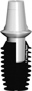
When the abutment head taper is reduced to less than 5 degrees (Morse taper), an increase in the frictional fit occurs. Several implant abutment designs use only the Morse taper, without threads, to fixate components together (Figure 28-14). The Morse taper has been called “cold welding” in advertising. However, no metal composition has changed, and limited strain is present in the connection, so this attachment is primarily a frictional fit.
Morse tapers in engineering are designed to make components easily retrievable, not to keep them fixated together.39 Any tensile or shear force will separate the individual pieces. Hence, a cantilever or angled force to the crown will transmit tensile and shear loads to the abutment and cause the Morse taper to loosen. The most common device that uses a Morse taper in dentistry is a dental lathe. As a result, the polishing wheels are more easily removed and replaced. Rather than threading a pumice wheel into position, only to unthread and thread a polishing wheel, a Morse taper permits the dentist to quickly remove and replace the components.
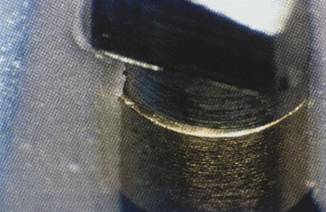
The same manufacturing conditions apply to impression transfer copings and analogs. Many manufacturers have a wider machining range (+ or – variance) for the prosthetic components to reduce the cost of manufacturing (Figure 28-15). Hence, when transfers and analogs are used in impressions and then to fabricate the prosthesis in the laboratory and the implants are splinted together, the casting may not passively seat.
Settling is a term used to describe the effect of parts wearing and fitting closer together. Minor irregularities on or within a casting that incorporates the top of an abutment for screw can cause slight elevation of the casting or the screw head. Over time, micromovement wears down the irregularities, and the parts fit closer together. However, this settling relaxes the preload force on the prosthetic screw and is more likely to cause screw loosening.
When a castable component is used, sandblasting alters the surface and therefore component fit. Chemically devastating the castings with a commercial acid has been advocated to decrease marring and damaging the coping. Polishing the abutments and coping margins with hardened stainless steel polishing caps to protect the coping abutment interface also is recommended.51
Plastic burnout prosthetic copings cost less, but they exhibit much greater laboratory variance and poor fit because of irregularities and settling of the superstructure. Besides cost, another advantage of a plastic burnout pattern for a coping is that one type of metal is used for the coping and superstructure, lessening the risk of metal corrosion or separation between the coping and superstructure.
To reduce settling, a machined coping may be used to fit the implant abutment more accurately. Some manufacturers suggest a titanium coping to reduce the risk of misfit. However, oxides form on the titanium machined coping surface and impair metal adherence when the prosthesis or abutment metal work is cast to the coping. Mechanical retentive features on the coping improve this metal-to-metal attachment.52
Laboratory studies demonstrate that an alloy-cylinder compatibility exists when noble metal alloys are used rather than titanium for a superior metal-to-metal connections. A machine coping connection is still present, so it is superior to the plastic components used to cast one metal.53 The risk of oxides forming between the coping and metal of the prosthesis is also reduced (see Figure 28-9).
Antirotational Features
As a general rule, most implant bodies have an antirotational feature for the abutment connection. The most common designs are an external hexagon, an internal hexagon, a Morse taper, and a Morse taper with threads.
Many manufacturers have stated that the internal connections are more esthetic for the implant crown. This is not true. The internal and external antirotational features have the same esthetic consequence. All external hexagon implant bodies have an abutment that has a matching internal hex. When the two components are connected together, they form a connecting line between them. The crown margin is placed above the connecting line of the abutment to implant body. All internal hexagon implant bodies have an abutment that has a matching external hexagon. When the two components are fixated together, they form a connecting line between them. Hence, after the abutment component is connected, there is no esthetic difference for the crown that is attached to the abutment (Figure 28-16).
Factors that affect the abutment screw connection and screw loosening include the height (or depth) of the hexagon and the platform diameter.47–49,54 Boggan et al. studied the influence of design factors on the mechanical strength and quality of fit of the implant abutment interface.54 Whereas failure mode for static test samples was bending or deformation of the abutment screw, fracture of the abutment screw was the common failure mode for the fatigue test samples. The static failure load was greater for the external hex implants of 1 mm in height compared with implants with an internal hexagon of 1.7 mm. The larger-diameter implant had the greatest static load before failure (Table 28-1).
TABLE 28-1
Failure Loads of Various Implant Types
| Implant Type | Static Failure Load (N) |
| 1.0-mm external hexagon, 4 mm | 966 |
| 1.0-mm external hexagon, 5 mm | 1955 |
| 0.7-mm external hexagon | 756 |
| 0.6-mm internal octagon | 587 |
| 1.7-mm internal hexagon | 814 |
A mechanical analysis of the abutment–implant interface was conducted to further clarify the importance of hexagon height (or depth) and platform diameter. The load on the abutment screw was shown to be a function of the hexagon height (or depth) and the platform diameter according to the following equation:
< ?xml:namespace prefix = "mml" />
where Fs is the load on abutment screw, P is the lateral load on the abutment, H is the abutment height, R2 is the reaction load of the implant hexagon on the abutment, h is the external hexagon height (or depth) of the implant, and D is the platform diameter of the implant.
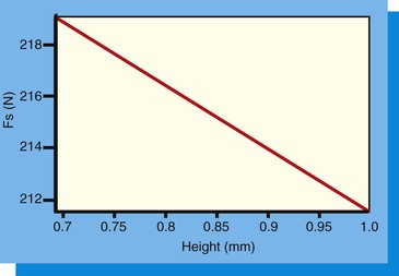
Use of this equation demonstrates that as the hexagon height (or depth) increases, the load on the abutment screw decreases. Likewise, as the diameter of the implant platform increases, the force on the abutment screw decreases. Reduction of the lateral load (P) on the abutment screw is important so as not to load the screw beyond the yield strength of the material or to reduce the number of cycles to fracture (because fatigue is related to both force and cycles).
Height (or Depth) of the Hexagon
The height (or depth) of the antirotational hexagon is directly related to the force applied to the abutment screw with any lateral load54 (Figure 28-17). Because the crown is connected to the abutment and the abutment rests on the implant platform, a lateral force on the crown creates a tipping force on the abutment. This tipping force is resisted by the hexagon height or depth, the platform, and the abutment screw. When the arc of rotation is above the hexagon height, all of the force is applied to the abutment screw. For the hexagon height to be above the arc of tipping forces, the hexagon height must be at least 1 mm for a 4-mm-diameter implant. Yet many implant manufacturers using a hexagon height have only a 0.7-mm hexagon, so almost all of the force is directed to the abutment screw and increases the occurrence of screw loosening and fracture.
The 0.7-mm hex dimension was the original design for the Nobelpharma titanium screw implant.55 In the research of Brånemark , the implant body was placed 1 mm below the bone crest, and a 1-mm-tall cover screw was placed over the external hex.56,57 This resulted in the implant and cover screw positioned level with the bone. When the implant was not countersunk, the external hex feature was above the bone and made it more difficult to obtain and maintain soft tissue closure. The external hex was only used to thread the implant into the bone. The cover screw and abutment did not engage the hex of the implant crest module. Hence, the height of the hex was not a prosthetic antirotation feature. The lower the hex height, the less countersunk the implant was in the bone.
When the internal hexagon implants were introduced, the internal connection did not alter the overall height of the implant platform position in the bone. The antirotation feature did not affect soft tissue closure. Hence, the hex dimension could be greater, and this additional height reduced the force on the abutment screw. In the static failure study of Boggan et al., the 1.7-mm internal hexagon had a greater load before failure than the 0.7-mm external hexagon.54 However, it was less than the 1.0-mm external hexagon implants (see Table 28-1).
Platform Diameter
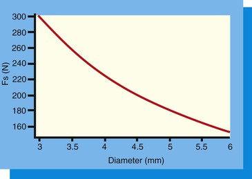
The platform diameter allows the abutment to seat on the implant crest module adjacent to the antirotational hexagon (external or internal). The tipping forces applied to the abutment form an arc with a radius from the outside abutment margin opposite to the force to the dimension of the hexagon on the same side of the force. The platform width resists the arc of rotation on the side opposite the tipping force. The narrower platform has a short fulcrum point and platform width and makes it more vulnerable to tipping forces. The wider the platform diameter, the more the resistance to the tipping forces. Therefore, the larger the platform diameter, the less force applied to the abutment screw.
In the Boggan et al. study, the force on the abutment screw was decreased by 12 units when the 0.7-mm hex height was increased to 1.0 mm. When the force on the screw was evaluated for a 4-mm-diameter implant compared with a 5-mm-diameter implant (with the same hex height), a decrease in force of 40 units was observed54 (Figure 28-18). In other words, the diameter of the implant (and corresponding platform dimension) was more important to reduce the risk of screw loosening than the height (or depth) of the antirotational hexagon. In a clinical report by Cho et al., abutment screw loosening was observed during a 3- to 7-year period in 14.5% of 4-mm-diameter implants. When a 5-mm-diameter implant supported the prosthesis, the screw loosening was reduced to 5.8%.58
Larger-diameter implants with a wider platform should be used to decrease the force applied to the abutment screw whenever external force factors are greater than usual. Hence, a wider implant in the canine or maxillary central incisor single-tooth restoration is suggested for bruxing patients.
The parameters that affect the incidence of abutment and prosthetic screw loosening are variable from one patient to another because the external force factors are different. The doctors should consider factors such as preload, implant position, implant number, and implant diameter to reduce this complication. Other factors are related to the specific implant product selected to support and retain the prosthesis. These include screw head design, thread design, metal composition, component fit, and screw diameter.
Method to Retighten Abutment Screws
A common complication of a threaded two-piece abutment is the loosening of the abutment screw from the implant body under a cement-retained crown, which remains luted to the abutment. Removing a cemented crown from a mobile abutment is often difficult. The impact force applied to the mobile crown is dissipated because of the loose abutment screw. In addition, when the crown margin is subgingival, it is difficult to engage with a crown remover.
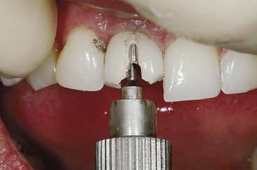
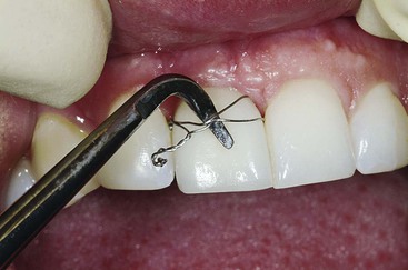
One option to tighten the abutment screw is to cut the crown off, tighten the abutment screw, and redo the crown (Figure 28-19). If the dentist cannot engage the subgingival margin with a crown and bridge remover, an orthodontic wire may be wrapped around the tooth below the interproximal contacts (Figure 28-20). A crown and bridge remover may then use the wire to apply the impact force to the cement seal.
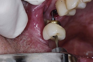
To solve this problem in the posterior regions of the mouth, the dentist may be able to drill an access hole through the occlusal aspect of the crown to gain access to the abutment screw (Figure 28-21). This procedure, however, may also damage the porcelain or the incisal edge of the crown and may mandate replacement of the crown.59
Stay updated, free dental videos. Join our Telegram channel
VIDEdental - Online dental courses


