2
2
Radiographic Analysis and Imaging
The standard radiographic views which are fundamental to orthognathic surgery planning consist of a panoramic screening radiograph, for example, an orthopantomogram, and a lateral skull radiograph taken in a cephalostat. In addition the posteroanterior skull radiograph may be used in cases where there is clinical evidence of asymmetry. More detailed radiographs, for example, long cone periapical views or an upper standard occlusal radiograph may be taken for clarification of specific areas of pathology. It is not uncommon for surgical patients to have previously undergone some form of orthodontic treatment and therefore it is important to ensure that the roots of the teeth are perfectly sound.
The Need
Cephalometric analysis is helpful in establishing the relations of:
- The maxilla and the mandible to the base of the skull.
- The maxilla to the mandible.
- The maxillary teeth to the maxilla.
- The mandibular teeth to the mandible.
- The upper incisors to the lower incisors.
In order for these measurements and relationships to be meaningful it is important that the radiograph is taken in a standardised centric relation position (retruded contact position) with the patient’s Frankfort Plane (the line from the lower border of the orbital rim to the upper border of the cephalostat ear post) horizontal. It is also important to ensure that the soft tissues are at rest when the radiograph is recorded.
Modern radiological guidelines require that intensifying screens should be used and that the radiographic beam has undergone appropriate collimation so as to avoid excessive exposure of structures considered unnecessary in the planning process.
Ethical approval is also required for repeated radiographs used for research purposes.
The Tracing
A sheet of clear, matt acetate paper is fixed securely with adhesive tape to the lateral skull radiograph placed on a horizontal viewing box. The radiographic image is enhanced by tracing in a darkened room with any peripheral light from the viewing box masked off. Many operators will have their preferred landmarks and analyses but the following outlines and points are commonly registered (Figure 2.1).
Outlines:
- The soft tissue profile including glabella, nasion, nasal tip, upper lip, lower lip and the soft tissue chin.
- The inner outline of the sella turcica, the anterior aspect of the nasal bones together with the frontonasal suture and the outline of the lower bony margin of the orbit.
- The maxillary outline, upper incisors and upper first molar.
- The mandibular outline with the mandibular incisors and first molar and articulare. As a result of superimposition it is often difficult to identify the head of the condyle but it is easy to register the articulare where the posterior margin of the ramus crosses the cranial base. In general, where bilateral landmarks present two images, the average of the two should be drawn. The exceptions to this are those cases where there is an obvious asymmetry of the mandible, which has resulted in two distinct lower borders to the mandible. From the point of view of measurement, it is normal practice to take the lower border which conforms to the normal side of the face, as assessed clinically.
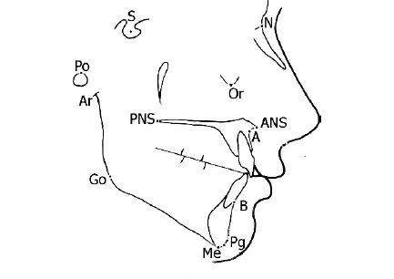
Figure 2.1 Cephalometric outlines and landmarks: A, point A; ANS, anterior nasal spine; Ar, articulare; B, point B; Go, gonion; Me, menton; N, nasion; Or, orbitale; PNS, posterior nasal spine; Pg, pogonion; Po, porion; S, sella.
Points:
- S Sella: The centre of the sella turcica determined by visual inspection.
- N Nasion: The anterior point of the frontonasal suture.
- ANS. Anterior nasal spine: Where the tip of the anterior nasal spine deviates markedly upwards or downwards, it is taken as the mid-point of the upper and lower spine outlines where it is 2 mm wide.
- PNS. Posterior nasal spine.
- Point A. The deepest midline point on the maxillary alveolus outlined between the anterior nasal spine and the maxillary alveolar crest.
- Point B. The deepest midline point between the mandibular alveolar crest and pogonion.
- Me Menton: The most inferior point on the lower border of the bony symphysis.
- Pg Pogonion: The most anterior point on the bony symphysis.
- Go Gonion: Is determined by bisecting the angle formed by tangents to the lower and posterior borders of the mandible. It is the point where the bisector cuts the angle of the mandible.
- Ar Articulare: The intersection of the posterior border of the ramus and the temporal bone.
- Co Condylion: The superior point on the condylar head.
- Or Orbitale: The most inferior point on the orbital margin.
- Po Porion: The upper margin of the bony external auditory meatus. The upper margin of the condylar head (Co) may also be used as it is often more easily determined.
- UMC. The tip of the mesio-buccal cusp of the upper first permanent molar.
- LMC. The tip of the mesio-buccal cusp of the lower first permanent molar.
- UIA. The tip of the post prominent maxillary incisor root apex.
- UIE. The most prominent maxillary incisor crown edge.
- LIE. The most prominent mandibular incisor crown edge.
- LIA. The tip of the most prominent mandibular incisor root apex.
The following lines are then drawn (Figure 2.2):
- S-N (the anterior cranial base).
- S-Ar.
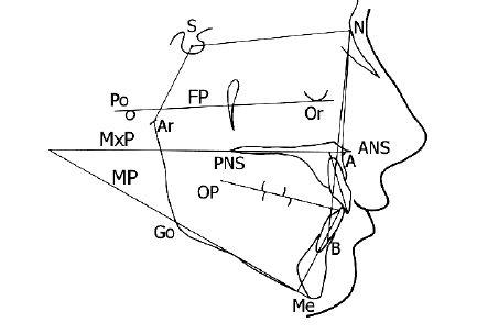
Figure 2.2 The planes and angles. Using the cephalometric points the following planes are constructed; SN plane (SN), mandibular plane (MP), maxillary plane (MxP) and Frankfort plane (FP). The long axes of the maxillary and mandibular incisors are considered relative to the maxillary and mandibular planes respectively. The important cephalometric angles can be readily derived from these points and planes. For key, see Table 2.1.
- N-A.
- N-B.
- Or-Po (the Frankfort plane-FP).
- ANS-PNS (the maxillary plane-MxP).
- Me-Go (mandibular plane-MP).
- Long axes of the upper (UI) and lower (LI) incisors.
- The occlusal plane (OP) is drawn through the outline of the buccal segment teeth, including the premolars. However, it may be difficult to determine the outline of the molars due to superimpositi/>
Stay updated, free dental videos. Join our Telegram channel
VIDEdental - Online dental courses


