CHAPTER 2
Exposure and Bonding of an Impacted Tooth
Neil C. Kanning,1 Scott A. Curtice,2 and Christopher J. Haggerty3
1Private Practice, Kanning Orthodontics, USA
2Department of Oral and Maxillofacial Surgery, Naval Medical Center San Diego, San, Diego, California, USA
3Private Practice, Lakewood Oral and Maxillofacial Surgery Specialists, Lees Summit; and Department of Oral and Maxillofacial Surgery, University of Missouri–Kansas City, Kansas City, Missouri, USA
A method of facilitating the eruption of severely impacted and/or malpositioned teeth with orthodontic guidance.
Indications
- Appropriate arch length to accommodate the impacted tooth within the alveolar arch
- Appropriate interdental space for the incorporation of the impacted tooth within the alveolus
- Erupted or impacted tooth on the contralateral side of the arch to provide appropriate symmetry
- Appropriately developed impacted tooth with no associated malformations or pathology
Contraindications
- When repositioning impacted teeth will create a structural weakness in the roots of adjacent teeth
- When other structures (i.e., adjacent roots, supernumerary teeth, and odontomas) are in the path of the anticipated distraction vector
- Impacted teeth that appear malformed or associated with pathology
Technique
- Local anesthesia is administered in the form of blocks and infiltration. Subperiosteal injection into the area of the anticipated mucoperiosteal flap will hydro-dissect the tissue and aid in hemostatic flap reflection.
- Primary teeth in the path of distraction and/or functioning as a space maintainer are extracted.
- A crestal incision is created within the area of the edentulous space or extraction site of the retained deciduous tooth. Incisions are designed to bisect the attached tissue overlying the alveolar ridge. This will allow the impacted tooth to be distracted through keratinized tissue and will lead to optimal periodontium supporting the tooth.
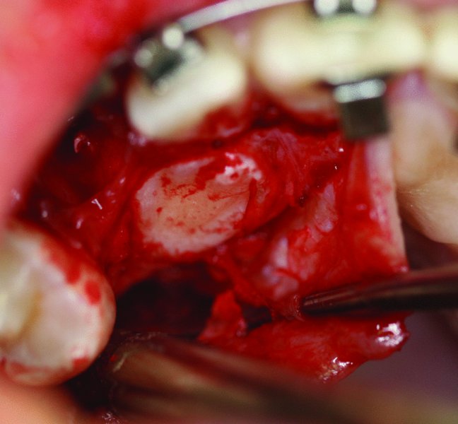
- A full-thickness mucoperiosteal flap is raised, with or without distal releasing incisions depending on the access needed to locate the impacted tooth (see Figure 2.6 in Case Report 2.1 and Figure 2.16 in Case Report 2.2).
- The impacted tooth is frequently identified as an area with a bulge and/or by the identification of the dental follicle. Thin superficial bone overlying the impacted tooth can be removed with a periosteal elevator (see Figure 2.16 in Case Report 2.2). If significant bone removal is required to expose the clinical crown of the impacted tooth, a small round bur with copious irrigation is utilized.
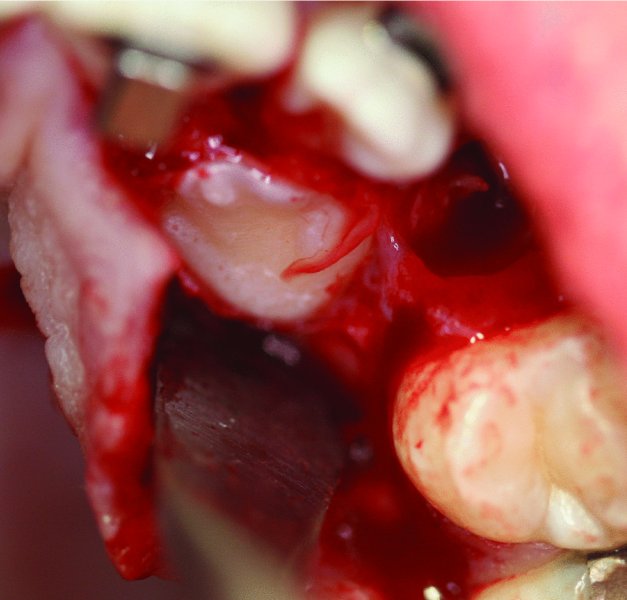
- Once the clinical crown of the impacted tooth is exposed, the dental follicle is removed with cautery (see Figure 2.7 in Case Report 2.1 and Figure 2.17 in Case Report 2.2). Cautery allows for quick and easy removal of the follicle and greatly adds to hemostasis.
- If needed, local anesthesia containing a vasoconstrictor can be injected into the surrounding tissue and around the clinical crown of the tooth to aid in hemostasis.
- A suction tip is placed at the tooth–bone interface to further enhance hemostasis and to aid in the creation of a dry field. A dry field is paramount to ensuring that the composite adheres and has a strong bond.
- Once a dry field is established and maintained, the bracket is placed toward the incisal or occlusal tip of the impacted tooth in the position of the ideal vector for the distraction of the tooth into the space created by the orthodontist or within the space created by the extraction of the primary tooth.
- Once the bracket is secured in the appropriate position, the chain attached to the bracket is tested with cotton pliers or pickups to ensure a strong bond between the composite and the impacted tooth. Excessive composite flange is removed with a round bur with copious irrigation.
- The chain is secured to the orthodontic archwire with 4-0 silk sutures. Excessive chain links are removed in order to minimize slack within the chain (see Figure 2.11 in Case Report 2.1 and Figure 2.18 in Case Report 2.2) as excessive chain slack can lead to bracket detachment.
- The area is closed primarily with interrupted 4-0 chromic sutures (see Figure 2.13 in Case Report 2.1).
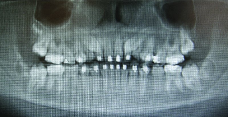
Figure 2.1. Orthopantomogram demonstrating retained primary teeth c and h and impacted teeth #6 and #11.
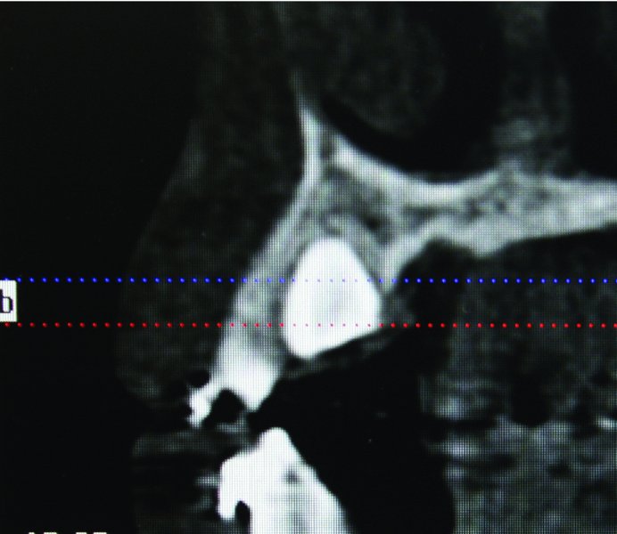
Figure 2.2. Cone beam computed tomography sagittal view demonstrating the palatal position of tooth #6.
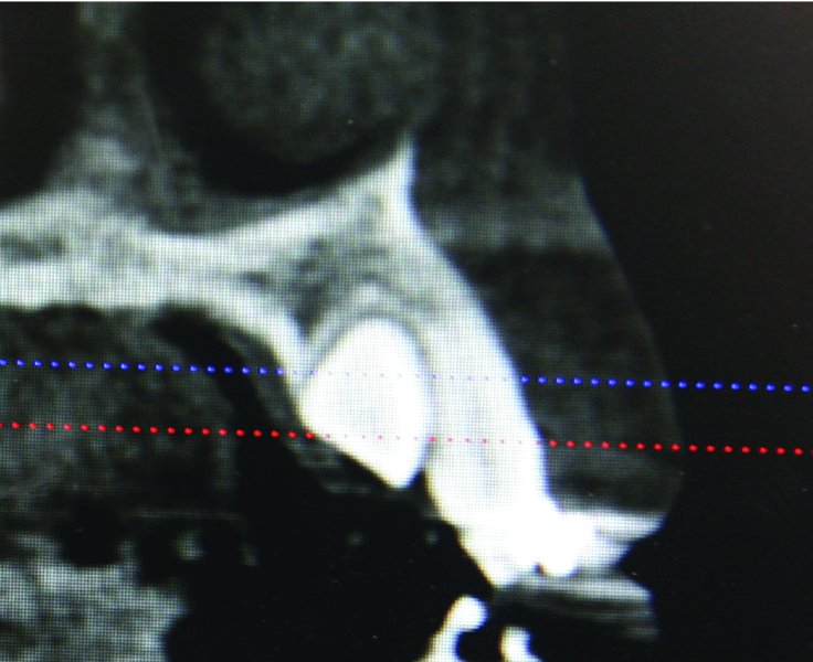
Figure 2.3. Cone beam computed tomography sagittal view demonstrating the palatal position of tooth #11.
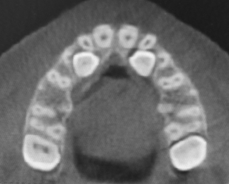
Figure 2.4. Occlusal view of impacted teeth #6 and #11.
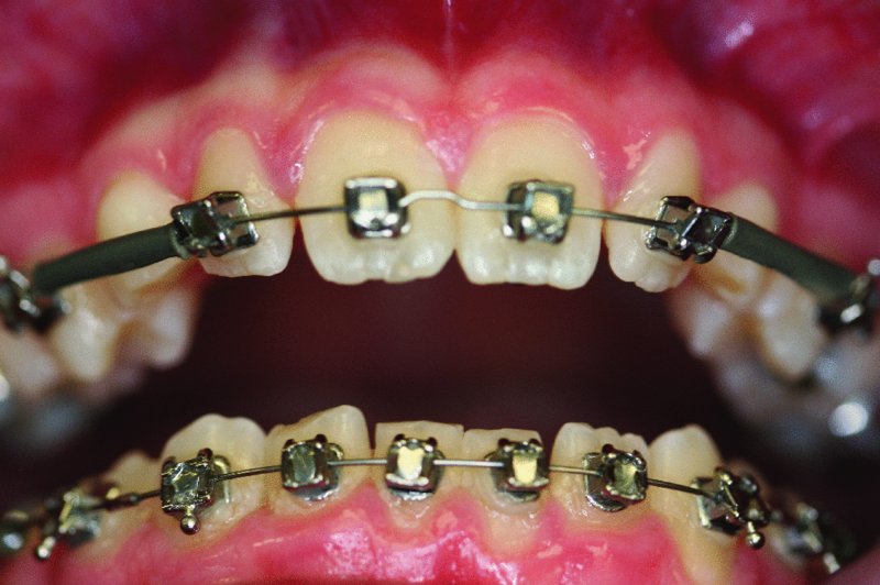
Figure 2.5. 14-year-old patient in full orthodontics with c and h acting as space maintainers for impacted teeth #6 and #11.
Stay updated, free dental videos. Join our Telegram channel
VIDEdental - Online dental courses


