2
Diagnosis and Treatment Planning
Diagnosis and treatment planning are the most important parts of the entire implant therapy, determining whether the treatment will be a success or a failure. Skipping any of the recommended steps of the treatment-planning phase compromises the outcome of the final treatment.
DIAGNOSTIC WORKUP FOR IMPLANT OVERDENTURE
BENEFITS OF DIAGNOSTIC MOUNTING
- Creates a surgical template
- Visualizes the relationship of the denture teeth with anticipated implant positions
- Gives the clinician and lab technician a good idea of the position and final design of the bar
- Creates an index for the position of the final overdenture teeth
In patients with a high smile line, a removable overdenture will more likely fulfill the patient’s functional and aesthetic demands better than an implant-supported fixed bridge. If the patient’s upper lip support needs to be enhanced, an implant-supported overdenture with a labial flange is the preferred choice of treatment.
If the relationship between the maxilla and mandible is unfavorable, such as class II or class III, or if excessive inter-ridge space is present, implant-supported overdentures are preferred over fixed bridges supported by implants.
RADIOGRAPHIC EVALUATION
Panoramic Radiograph
The panoramic radiograph is the most common image used to evaluate implant overdenture cases. This radiograph produces a single image of the maxilla and mandible with all of the anatomical landmarks in a frontal plane. It is very cost effective and practical, because it can be generated in most dental offices. The clinician can easily identify the gross anatomy of the jaws and opposing landmarks, as well as form an initial assessment of the vertical height of the bone. Any pathology within the maxillary and/or mandibular bone can be detected. The patient is exposed to a relatively low radiation dose compared to a CT scan or conventional tomogram.
However, the panoramic radiograph has several disadvantages such as overlapping images, distortion of the special relationship among anatomical landmarks, and magnification errors. Also, fine anatomical details cannot be seen as they appear on a CT scan. This radiograph usually increases the horizontal dimension by about 30–70 percent and increases the vertical dimension by about 20–30 percent.
The use of a diagnostic template while taking the panoramic x-ray can effectively eliminate the magnification error. The diagnostic template is an acrylic base, which has been fabricated over the study cast.
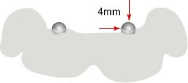
One or more ball bearings (BBs) should be incorporated into the template using self-cured acrylic. Place the BBs as close as possible to the desired implant sites (Figure 2.3).
DETERMINING MAGNIFICATION ERROR OF PANORAMIC X-RAYS
PANORAMIC LANDMARKS
- Crest of the ridge
- Opposing landmarks
- Anterior: Inferior border of the symphysis
- Canine/Premolar Region: Mental foramina
- Posterior: Mandibular nerve canal
- Anterior: Inferior border of the nasal cavity
- Canine/Premolar Region: Lateral walls of the nasal cavity and anterior border of the maxillary sinus
- Posterior: Floor of the maxillary sinus
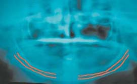
During treatment planning for a mandibular implant overdenture, this radiograph can provide a fair approximation of the position of the most distal supporting implants. The position of the mental nerve, the path of the mandibular nerve canal, and the height of the alveolar ridge have a great influence on the position of most distal implants.
The mandibular nerve canal generally extends 3–4mm anterior to the mental foramen. However, the mandibular nerve may loop forward 6–7mm in some patients. It is recommended that you position the center of the distal implant 7mm mesial to the mental foramen to eliminate any possibility of nerve injury. Note that all anatomical variations are patient-specific.
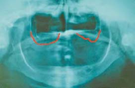
Occlusal Radiograph
An occlusal radiographic image is very helpful in assessing the width of the bone in the mandibular symphysis area. Employ proper techniques such as symmetrical positioning of the central ray and the film.
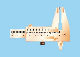
Make an acrylic base on the lower cast and glue a 5mm diameter ball bearing to the side of the acrylic base in the symphysis area. The patient should wear this acrylic base when the image is taken. Changes in the diameter of the ball bearing in the radiograph will help the clinician determine the magnification error of the radiograph.
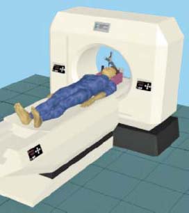
Computed Tomography (CT Scan)
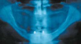
Since plain films fail to provide data on bone width and bone density, clinicians started utilizing CT scan technology to enhance their diagnostic and treatment planning abilities (Figure 2.7).
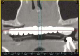
The CT scan creates three-dimensional images of the edentulous arches at 1.00mm intervals from left to right around the entire dental arch in both the mandible and maxilla. The images (cross sections) are sequentially numbered. The clinician has at his or her disposal cross-sectional, panoramic, and occlusal views of the actual osseous topography. This radiographic technology results in no magnification error, and all of the images have the exact same dimensions as the patient’s anatomical structure being examined. Therefore, this scan permits precise measurement of the bony structure that is relevant to the desirable implant locations in all three planes.
The techniques for producing clinically useful CT image vary, depending upon the equipment employed. However, regardless of the type of equipment, the thickness of each cut must be 1mm or less.
Placing a radioopaque material such as special barium sulfate teeth as a marker in the diagnostic guide identifies the desired site for an implant placement (Figure 2.8). This allows the clinician to see the makers on the CT images and evaluate the underlying bony structure.
CT analysis of the jaws is normally very expensive; the technique is therefore generally used only if additional diagnostic information is necessary due to anatomical complexity or other diagnostic difficulties. The need to assess accurately the position of the inferior alveolar canal, the mental foramen, the contour of the lingual surface of the mandible, and the floor of the sinuses are primary indications for using a CT scan during the treatment planning phase for implant overdenture cases. The advantages of CT scanning when planning for the placement of dental implants must be balanced against the cost and the amount of the radiation exposure incurred with CT scans.
JOINT TREATMENT PLANNING
The next phase in the treatment planning process involves an effective conference among the entire implant team, which consists of the restorative dentist, surgeon, and laboratory technician, along with any number of supporting members such as the hygienist and the representative of the implant company.
The crucial factor in building an effective conference is to create a team of people, each of whom knows his or her job and can perform it well. Each member of the team must be committed to listening as well as sharing his or her ideas and observations. Ideally, the treatment planning conference should be done in person. However, it can be conducted via telephone or web conferencing.
The leader of this team will be the restorative dentist. He or she begins the communication with the patient regarding the patient’s chief complaint and continues that communication throughout the treatment process and beyond. The secondary leaders in this process are the surgeon and the laboratory technician.
ANATOMICAL CONSIDERATIONS DURING DIAGNOSIS AND TREATMENT PLANNING PROCESS
Available Bone Quantity
Bone quantity is one of the most important factors that dictate the treatment plan. The height, width, length, and shape of the available bone should be assessed.
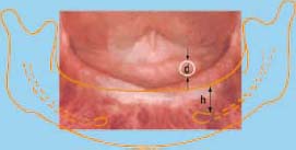
HEIGHT OF BONE The distance between the crest of the alveolar ridge and opposing anatomical landmarks (e.g., maxilla: floor of the sinuses and the nasal cavity; mandible: the mandibular nerve canal, mental foramina, and inferior border of the symphysis) determines the height of the bone. It is advisable to leave 2mm between the bottom of the implant and border of the opposing landmark. The height of the bone can easily be determined through a panoramic x-ray.
WIDTH OF BONE The distance between the buccal and lingual walls of the alveolar process determines the width of the bone. It is recommended that at least 1mm thickness of the bone should remain on the buccal and lingual aspects of the implants. Very thin buccal and lingual bone plates around the implant will have a compromised blood supply and increase the risk of bone loss. The width of the bone cannot be determined by a panoramic x-ray. However, the occlusal x-ray or the CT scan will provide suitable images for measuring the width of the bone.
SHAPE OF BONE The shape of the alveolar ridge influences the clinician’s selection of the shape of the implant body (e.g. choosing a tapered implant vs. parallel sided screw). The shape of the bone influences the trajectory of the implant, which is not always inline with the path of insertion of the overdenture. This problem can cause application of destructive forces to the supporting implants. The shape of the bone can be modified by bone grafting techniques or alveoloplasty.
LENGTH OF BONE The distance from one point of the alveolar ridge to another point in the mesio-distal direction determines the length of the bone. The mesio-distal distance between the supporting implants will be determined based on the design of the attachment assembly.
Misch and Judy described an easy and practical classification for fully edentulous jaws based on the available bone.
Classification of Fully Edentulous Ridges Based on Bone Quantity
GROUP A There is minimum bone loss, which translates to less inter-ridge space. On average, the height of the bone in the anterior mandible is more than 20mm, and the width of the bone is more than 5mm (Figure 2.9). The height of the bone in the anterior maxilla is usually more than 15mm, and most of the time the width of the bone is more than 5mm. Because of small inter-ridge space, patients in this group are not good candidates for a bar attachment assembly. Insufficient room is available to fabricate a cleansable bar a/>
Stay updated, free dental videos. Join our Telegram channel
VIDEdental - Online dental courses


