Oral Radiography
Learning Objectives
1 Pronounce, define, and spell the Key Terms.
4 Identify errors in exposure technique, and describe the steps necessary for prevention.
5 Identify errors in processing technique, and describe the steps for prevention.
6 Demonstrate the infection control techniques necessary for manual and automatic film processing.
7 List the steps in manual processing and in automatic processing of dental radiographs.
8 Mount a full series of periapical and bite-wing dental radiographs.
9 Describe the purpose and uses of panoramic imaging.
10 Describe the equipment used in panoramic imaging.
11 Describe the steps for patient positioning in panoramic imaging.
12 Discuss the advantages and disadvantages of panoramic imaging.
13 Describe the basic concepts of digital imaging.
15 Explain the advantages and disadvantages of digital radiography.
Key Terms
Automatic Processing Techniques
Bisecting Angle Technique
Bite-Wing Image
Cassette
Charge-Coupled Device (CCD)
Diagnostic Quality Image
Digital Image
Digitized
Film Duplicating
Horizontal Angulation
Latent Image
Manual Processing
Occlusal Technique
Panoramic Radiography
Paralleling Technique
Periapical Views
Phosphor Storage Plates (PSP)
Point of Entry
Positioning Instrument
Radiograph
Scanning
Sensor-Holding Devices
Teledentistry
Vertical Angulation
In the modern dental office, digital radiography is rapidly replacing traditional film-based techniques. When discussing digital radiography, the term digital image is used instead of radiograph, film, or x-rays. A radiograph is an image on a conventional dental film.
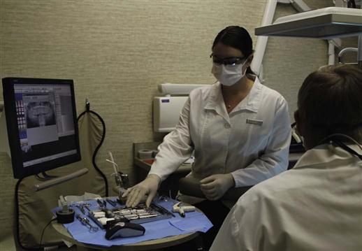
It is important for the dental assistant to be competent with all forms of dental radiography. You must also be familiar with dental x-ray equipment, dental-x-ray film, and film- or sensor-holding devices (Figure 16-1).
Intraoral Views
Types of Intraoral Views
There are three types of intraoral views. Each type of view provides specific information (Table 16-1). The three types of intraoral views are:
TABLE 16-1
< ?comst?>
| Type | Primary Uses | Example |
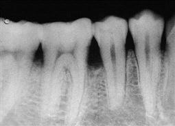
| Periapical | Shows images of the entire length of the tooth, plus 3 to 4 mm beyond the apices. Diagnoses, abscesses, or other pathologic conditions around the root area of the teeth. Also used to identify unerupted teeth |
 |
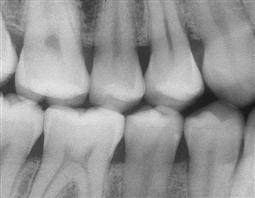
| Bite-wing | Shows images of the crowns of the teeth on both arches on one film. A bite-wing survey (BWX) can consist of two or four films. Used to diagnose interproximal caries, recurrent caries, pulpal pathologic conditions, and condition of the crestal bone |
 |
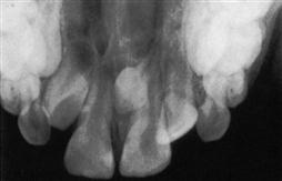
| Occlusal | Used to locate impactions, supernumerary teeth, pathologic conditions, and fractures of the maxilla or mandible. No. 4 film is used. |
 |
< ?comen?>< ?comst1?>
< ?comst1?>
< ?comen1?>
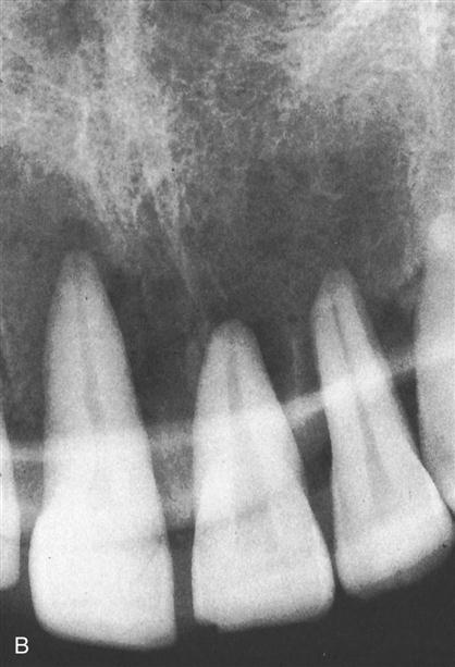
Occlusal radiograph from Miles DA, Van Dis ML, Williamson GF, et al: Radiographic imaging for the dental team, ed 4, Philadelphia, 2009, Saunders.
Film-Based Radiography
Placing a film in the patient’s mouth and then exposing it to a beam of x-rays captures the image on the film to make dental radiographs. The latent image (invisible) on the film becomes visible only after the film is processed in a darkroom (a light-tight room) or in an automatic film-processing machine. Once the film is processed and dried, it becomes a radiograph; it is placed into a film mount and is ready to be viewed and interpreted by the dentist.
Intraoral Dental X-Ray Film
The Film Packet
A film packet consists of an outer wrap, a lead foil, black paper, and one or two films (Figure 16-2).
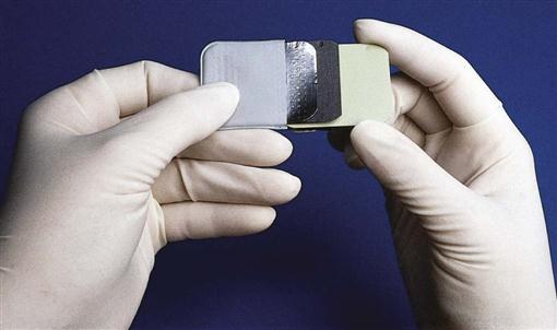
The front of the packet is white. This side is always placed toward the position indicator device (PID). The back, which is colored and has the tab used for opening the packet before processing, is always placed away from the PID. A small circle on the back indicates where the embossed dot, or raised bump, is on the film. This dot will aid later in mounting and determining the right side from the left.
Within the packet, the film is protected on either side by a sheet of black paper; a thin sheet of lead foil absorbs most of the x-rays that pass through the film (thus protecting the patient).
Double Film Packets
Double film packets contain two pieces of film between the black paper lining. This makes it possible to produce a duplicate set of the radiographs without exposing the patient to additional radiation or having to go through the film duplicating process.
Double film packets are useful when the insurance company requests radiographs or when a patient is referred to a specialist.
X-Ray Film
Intraoral dental film consists of a semiflexible plastic film base coated on both sides with an emulsion containing x-ray–sensitive crystals of silver bromide, silver halide, and silver iodine embedded in gelatin. The size of the crystals determines the film speed. (Film speed is discussed in Chapter 15.) These are numbered from 0 to 4, with 0 being the smallest (Figure 16-3 and Table 16-2).
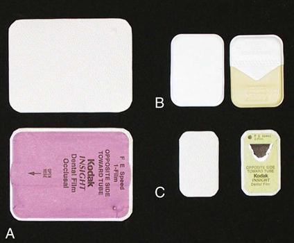
TABLE 16-2
| Size | Uses |
| 0 | Usually for children younger than 3 years |
| 1 | Anterior film for adult full-mouth surveys |
| 2 | Adult BWXs and adult posterior periapicals |
| 3 | Less common, but used for adult BWX |
| 4 | Occlusal radiographs |
Care of Dental Films
Film Storage
All dental films should be stored according to the manufacturer’s instructions. This includes storing them so that they are protected from light, heat, moisture, chemicals, and scatter radiation. The box of radiographic film is marked with an expiration date.
Film Care During Exposure
Films to be exposed are dispensed before the radiographic procedure begins. They are placed on a clean towel just outside the room where the films are to be exposed.
Never leave films, whether exposed or unexposed, in the room where additional films are being exposed. This could result in the new films being exposed to scatter radiation, which results in film fog and reduces their diagnostic value.
Infection Control in Dental Radiography
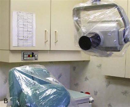
Dental radiographic procedures present special infection control challenges (Box 16-1). The operator contacts the patient’s saliva while placing and removing the film packets or sensors, and touches many things while exposing and processing film. Protective measures and barriers used while producing radiographs are illustrated in Figure 16-4. Dental film is now available with plastic barriers over the packet. The film is exposed as usual, and then the plastic barrier cover is removed before entering the darkroom for processing. The infection control protocol is more efficient and effective when the dental assistant plans for the procedure before the patient is seated (Box 16-2 and see Procedure 16-1).
Intraoral Radiography Techniques
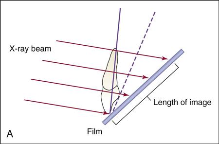
Regardless of whether you are using conventional film-based techniques or digital techniques, two basic techniques are used to obtain periapical views: the paralleling technique and the bisecting angle technique. The paralleling technique is preferred because it provides a more accurate image of the teeth and surrounding structures. The bisecting angle technique is discussed in this chapter as a supplemental method (Figure 16-5).
The Paralleling Technique
Basic Principles
Two basic principles define the paralleling technique: (1) The film is placed parallel to the long axis of the teeth being radiographed, and (2) the x-ray beam is directed at right angles (perpendicular) to the film or sensor and the long axis of the tooth.
Film/Sensor-Holding Instruments
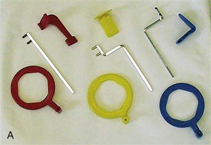
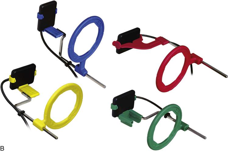
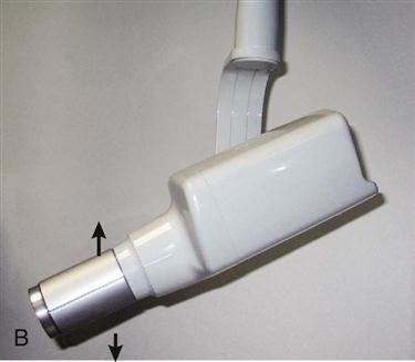
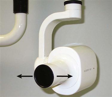
To place and keep the film packet or sensor in its proper position in relation to the tooth, the paralleling technique requires the use of film- or sensor-holding instruments. A variety of film/sensor-holding instruments are available (Figure 16-6).
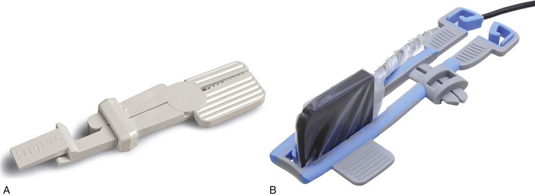
A commonly used type of film/sensor-holding instrument is the Rinn XCP (extension cone paralleling) instrument (Figure 16-7). In addition to film/sensor positioning, these instruments include a localizing ring, also known as an aiming ring, which facilitates aligning the PID with the film/sensor in both horizontal and vertical planes. This increases accuracy and reduces the need for unnecessary retakes. The procedures that follow at the end of this chapter include the use of XCP film/sensor-holding instruments; however, the basic principles of placement and paralleling are similar regardless of the film/sensor-holding instrument that is used (see Procedure 16-2).
Using the Paralleling Technique
Important factors to be considered in exposing periapical views include the dental chair position, film/sensor position and placement, point of entry of the x-ray beam, vertical and horizontal angulation, and the use of a film/sensor-holding instrument.
Dental Chair Position
The dental chair is positioned so the patient’s head is straight. For most exposures, this means that the patient is seated in an upright position. This position is adjusted so that the occlusal plane of the jaw being radiographed is parallel to the floor when the film/sensor is in position.
Film/Sensor Placement and Position
The film/sensor is placed in a vertical position for anterior projections and in a horizontal position for posterior periapical projections. The film/sensor is held in position by the patient closing on a bite-block or other film/sensor-holding device.
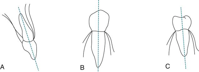
When conventional film is used, the film is placed so that the raised dot is toward the occlusal surface and is facing the PID. This technique places the front of the film packet toward the PID, prevents the dots from becoming superimposed over the apex of a tooth, and later aids in mounting the processed film. The film position must be parallel to the entire tooth, not just parallel to the crown. This is an important concept to understand. Although the crowns of the teeth appear to tilt one way, the entire structure actually tilts another. For example, the apices of most of the maxillary teeth tilt inward toward the palate. The mandibular premolars are more nearly vertical, and the mandibular molars tilt inward slightly (Figure 16-8).
To achieve parallelism between the long axes of the teeth and the film/sensor, the film/sensor must be placed slightly away from the teeth toward the midline of the oral cavity. In addition, film/sensors that are placed too close to the teeth may not record enough tissue in the area of the root apices. The film/sensor must be positioned away from the teeth, with the patient biting near the anterior edge of the bite-block.
Point of Entry
The point of entry is the position on the patient’s face at which the central x-ray beam is aimed. The goal is to completely cover the film/sensor with the beam of radiation.
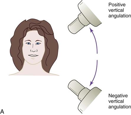
Vertical Angulation
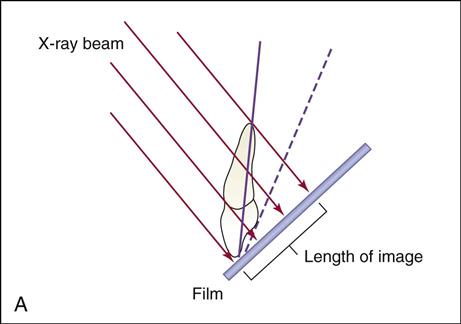
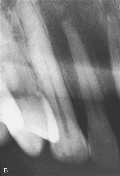
Vertical angulation is the movement of the tubehead in an up-and-down direction, similar to shaking your head “yes” (Figure 16-9). In the paralleling technique, the vertical angulation must be perpendicular to the film/sensor and to the long axes of the teeth, or images will be elongated or foreshortened (Figures 16-10 and 16-11).
Horizontal Angulation
Horizontal angulation is the movement of the tubehead in a side-to-side direction, similar to shaking your head “no” (Figure 16-12). In the paralleling technique, the horizontal angulation of the x-ray beam must be directed through the contacts of the teeth and be as perpendicular (perpendicular means at a right angle with the film/sensor) to the horizontal plane of the film/sensor as possible. Failure to do this will cause overlapping of proximal contacts (Figure 16-13).
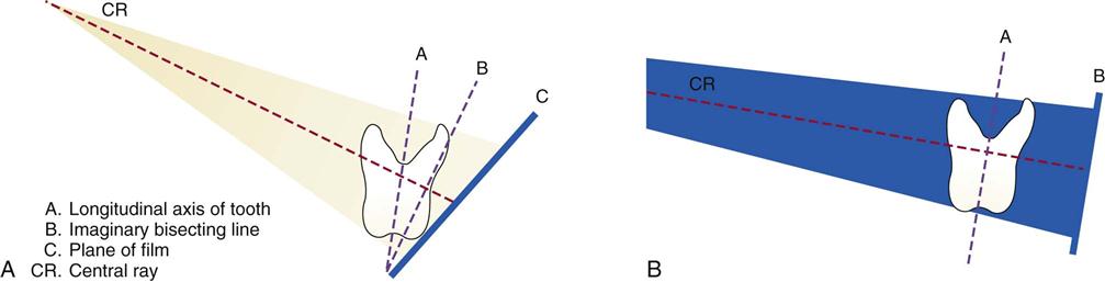
The Bisecting Angle Technique
The bisecting angle technique can be used in some special circumstances, for example, in difficult or unusual anatomy, such as in patients with a very shallow palate or a very short lingual frenum, or when palatal or mandibular tori (bone growths) are present. In addition, small children and some endodontic views may require use of this technique. Using proper technique, diagnostic images can be obtained with this method.
Basic Principles
The bisecting angle technique is based on the geometric principle of bisecting a triangle (bisecting means dividing into two equal parts) (Figure 16-14).
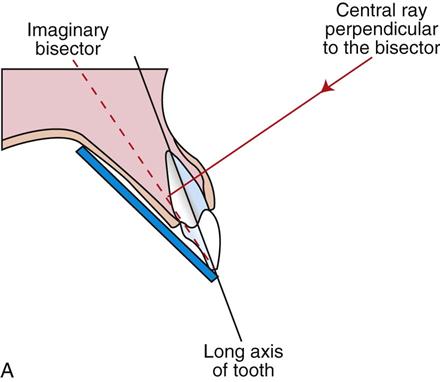
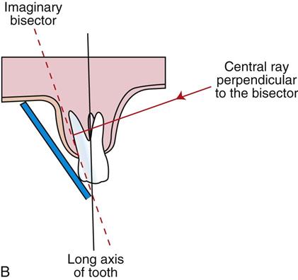
The angle formed by the long axis of the teeth and the film/sensor is bisected, and the x-ray beam is directed at a right angle (perpendicular) to the bisecting line.
In this technique, the film/sensor is placed close to the crowns of the teeth to be radiographed and extends at an angle into the palate or floor of the mouth. Film/sensor holders for the bisecting angle technique, including some with alignment indicators, are available commercially.
Patient Positioning
The patient’s midsagittal plane should be perpendicular to the floor. This means that the patient’s head is upright for maxillary film and is tipped back slightly for the mandibular arch.
A No. 2 film/sensor is used in both the anterior (in a vertical position) and posterior (in a horizontal position) regions. Only three films are needed in the maxillary anterior region because all four maxillary incisors can be imaged on the No. 2 film/sensor.
Beam Alignment
The x-ray beam is directed to pass between the contacts of the teeth being radiographed in the horizontal dimension, just as it does in the paralleling technique. The vertical angle, however, must be directed at 90 degrees to the imaginary bisecting line. Too much vertical angulation will produce images that are too short (foreshortened), and too little vertical angulation will result in images that are too long (elongated). The beam must be centered to prevent cone cutting. A short or a long PID can be used (Table 16-3).
TABLE 16-3
Vertical Angulations for Bisecting Angle Technique
| Teeth Being Imaged | Vertical Angulations |
| Maxillary incisors | −40 to −50 degrees |
| Maxillary cuspids | −45 to −55 degrees |
| Maxillary premolars | −30 to −40 degrees |
| Maxillary molars | −20 to −30 degrees |
| Mandibular incisors | −15 to −25 degrees |
| Mandibular cuspids | −20 to −30 degrees |
| Mandibular premolars | −10 to −15 degrees |
| Mandibular molars | −5 to 0 degrees |
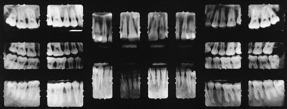
The Full-Mouth Radiographic Survey
A full-mouth radiographic survey (FMX) consists of a specified number of periapical and bite-wing views. A complete full-mouth survey may have as few as 10 or as many as 18 periapical views, plus whatever bite-wing views are indicated. The number and size of the film/sensor to be used depend on:
The procedure described here includes positioning and steps for each exposure in one half of the maxillary arch and one half of the mandibular arch with use of the paralleling technique and XCP film/sensor-holding instruments (Box 16-3).
When the opposite side of each arch is radiographed, the same procedures are followed. The completed radiographic survey is shown in Figure 16-15 (see Procedure 16-3).
Producing Bite-Wing Views
Bite-wing views are always parallel films regardless of the technique used for the periapical radiographs (see Procedure 16-4).
The film/sensor is positioned (by a bite tab or by a holding device) parallel to the crowns of both upper and lower teeth, and the central ray (CR) is directed perpendicular to the film/sensor.
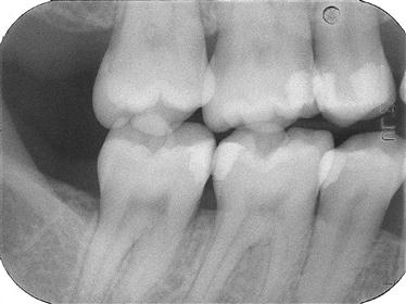
The premolar bite-wing image should include the distal half of the crowns of the cuspids, both premolars, and often the first molars on both the maxillary and mandibular arches. The molar film should be centered over the second molars.
Correct horizontal angulation is crucial to the diagnostic value of a bite-wing view. Even a slight amount of overlapping of the proximal (contact) surfaces on the image may lead to a misdiagnosis.
The Occlusal Technique
The occlusal technique is used to examine large areas of the upper or lower jaw (Box 16-4). The occlusal technique is so named because the patient bites or “occludes” the entire film. This technique requires the use of conventional dental film. In adults, No. 4 intraoral film is used, but No. 2 film is used in children. The occlusal technique is used when large areas of the maxilla or mandible must be radiographed (see Procedure 16-5).
Basic Principles
Exposure and Technique Errors
A diagnostic quality image is one that has been properly placed, exposed, and processed. Only diagnostic quality images are of benefit to the dentist, and retakes require the patient to be subjected to additional radiation. It is important for the dental assistant to recognize errors, identify their causes, and know how to correct the problem (Table 16-4).
TABLE 16-4
< ?comst?>
| Error | Cause |
| Clear film | Machine was not on. |
| Machine malfunction occurred. | |
| Elongation | Vertical angulation was too flat (low). |
| Overlapping | The central ray was not directed through the interproximal surfaces. |
| Cone cutting | The x-ray beam did not cover the entire film. |
| Herringbone effect | The film was placed backward in the mouth. |
| Double exposure | The same film was accidentally exposed twice. |
| Blurred images | The patient moved during the exposure. |
| Film bending | The film was bent to compensate for curvature of the mouth. |
| Underexposure | Exposure was insufficient. |
| Overexposure | Exposure was excessive. |
| Foreshortening | Vertical angulation was too steep. |
| Missing apical structures | The film was not placed deep enough on the mandibular arch or high enough on the maxillary arch. |
| Occlusal plane tilted | The film was not placed in position, or it slipped out of position. |
| Distorted images on bite-wing | Vertical angulation was incorrect. Always use a −10 degree vertical for bite-wing surveys (BWXs). |
< ?comen?>< ?comst1?>
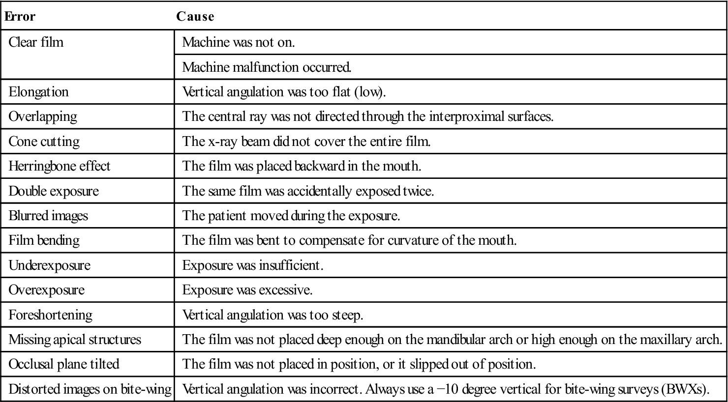
< ?comst1?>
< ?comen1?>
Processing Radiographs
Processing dental film consists of a series of steps that change the latent image (invisible) into a visible image on the radiograph. Most practices now use an automatic processor on their films. However, in some dental offices, it is necessary to know how to process the film manually. This section discusses both methods.
Infection Control During Film Processing
After you complete the exposures, remove your gloves and wash your hands. Carefully carry the paper cup or plastic bag containing the contaminated films to the processing area. Be careful not to touch the contaminated films with your bare hands. Regardless of whether you use a manual or an automatic processor with a daylight loader, you must remember that the used film packets are considered contaminated and should be handled appropriately (see Procedures 16-6 and 16-7).
Processing Solutions
Processing solutions are considered to be hazardous chemicals and are subject to special chemical labeling and disposal requirements. Always wear your personal protective equipment when handling these chemicals, and check disposal requirements specific to your state.
Care and Maintenance of Processing Solutions
You must always follow the manufacturer’s instructions for storage, mixing, and use of the processing solution (developer, fixer, and replenisher). These solutions deteriorate with exposure to air, continued use, and chemical contamination. Overused and old solutions cause radiographs to be too light and nondiagnostic (Table 16-5).
TABLE 16-5
Maintenance of Processing Solutions
| Type of Processing Chemicals | Schedule of Maintenance |
| Manual chemicals | Solutions should be changed every 3 to 4 weeks. |
| Automatic chemicals | Solutions should be changed every 2 to 6 weeks. |
| Replenisher chemicals | Developer and fixer solutions should be replenished daily in both manual and automatic processing. Follow the manufacturer’s instructions for the amount to remove and replace. |
Developer Solution
The first step in processing begins with the developer solution. The developer solution softens the emulsion. After developing, partially processed films are rinsed in water to remove any remaining chemical.
Note: There must no exposure to light at this point in the processing or the film will turn black.
Fixer Solution
The fixer solution removes the unexposed silver halide crystals and creates white to clear areas on the radiograph.
After the films have been fixed, they are thoroughly washed in water to remove any remaining chemicals.
Replenisher Solution
Replenishers are solutions of developer and fixer that are added to compensate for loss of volume and strength of the solutions that results from use.
Manual Processing
Manual processing depends on a combination of:
Note: Both are critical for successful processing of film (see Procedure 16-8).
The Darkroom
Manual film processing requires that the darkroom (Figure 16-16) be light-tight and have adequate working space, have good ventilation, and be clean and dry at all times. It should be equipped with the following:
• Items required for infection control (i.e., gloves, disinfectant spray, paper towels, etc.)
• Disposal container for contaminated film packets or barriers
• Recycle container for lead foil pieces (Caution: Lead should not be thrown in the trash.)
• Separate processing tanks for the developer solution, the rinse water, and the fixer solution
• A hot and cold running water supply, with mixing valves to adjust the temperature
• A timer accurate to minutes and seconds
• An accurate thermometer that floats in the tanks to indicate the temperature of solutions
• A stirring rod or paddle to mix the chemicals and equalize the temperature of solutions
Processing Tanks
In most darkrooms, the developer solution is in the tank on the left, the water bath (rinse) is the center tank, and the fixer solution is in the tank on the right. Always check the location of each chemical before processing.
Keep the tank covered except when placing and removing films to prevent evaporation of the solutions.
Automatic Film Processing
Automatic film processing is a simple method used to process dental x-ray films (Box 16-5 and see Procedure 16-9).
An automatic film processor is composed of a series of rollers that transport the films through the steps and solutions necessary for complete processing (Figure 16-17).
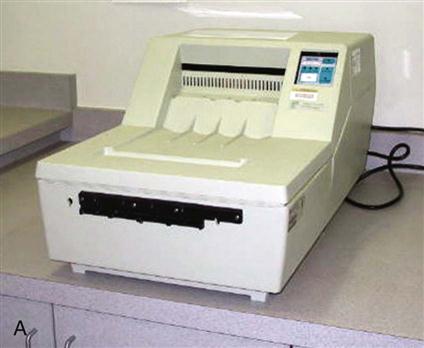
The temperature of the developer in automatic processors ranges from 85° F to 105° F (29.4° C to 40.5° C). This significantly reduces the developing and overall processing time. Automatic film processing requires only 4 to 6 minutes to develop, fix, wash, and dry a film, whereas manual processing and drying techniques require approximately 1 hour.
Units with a daylight loading capability do not require a darkroom because they have light-tight baffles into which the hands are placed while the film is opened and inserted into the rollers. In a daylight loading unit, the exposed film is unwrapped and processed within the machine.
An automatic processor without daylight loading capability requires the use of a darkroom while unwrapping and placing films into the processor.
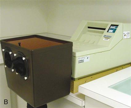
Care of the Automatic Processor
The automatic processor must be routinely cleaned and disinfected according to the manufacturer’s directions. In addition, automatic processors must have routine preventive maintenance.
The two most common causes of automatic processor breakdown are (1) failure to keep the rollers clean and (2) inadequate replenishing of chemicals. The manufacturer’s recommendations for daily and monthly cleaning of the automatic processor must be carefully followed.
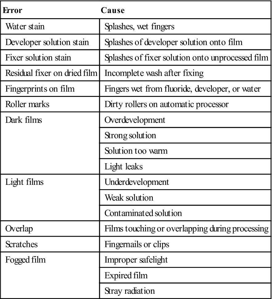
Processing Errors
Proper processing of exposed film is just as important as the exposure technique in producing diagnostic quality radiographs. You should readily recognize errors and understand how to avoid them (Table 16-6).
TABLE 16-6
< ?comst?>
| Error | Cause |
| Water stain | Splashes, wet fingers |
| Developer solution stain | Splashes of developer solution onto film |
| Fixer solution stain | Splashes of fixer solution onto unprocessed film |
| Residual fixer on dried film | Incomplete wash after fixing |
| Fingerprints on film | Fingers wet from fluoride, developer, or water |
| Roller marks | Dirty rollers on automatic processor |
| Dark films | Overdevelopment |
| Strong solution | |
| Solution too warm | |
| Light leaks | |
| Light films | Underdevelopment |
| Weak solution | |
| Contaminated solution | |
| Overlap | Films touching or overlapping during processing |
| Scratches | Fingernails or clips |
| Fogged film | Improper safelight |
| Expired film | |
| Stray radiation |
< ?comen?>< ?comst1?>
< ?comst1?>
< ?comen1?>
Duplicating Radiographs
Duplicate radiographs are identical copies of an intraoral or an extraoral radiograph; they may be necessary when:
Equipment and Film Requirements
To duplicate radiographs, you will need a special duplicating type of film and a duplicating machine (Figure 16-18).
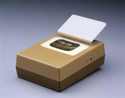
Duplicating film is used only for duplication and is never exposed to x-rays. Duplicating film is available in periapical sizes and in 5 × 12 inch and 8 × 10 inch sheets.
The duplicating machine uses white light to expose the film. Because the film is light sensitive, the duplication process is performed in the darkroom with the safelight.
Note: The longer the duplicating film is exposed to light, the lighter the duplicate films will become. This is the opposite of x-ray films, which will become darker when exposed to light.
Steps in Duplicating Radiographs
Mounting Radiographs
Processed radiographs are arranged in anatomic order in holders, called mounts, to make it easier for the dentist to study and review the film (see Procedure 16-10). The mount is always labeled with the patient’s name and the date that the radiographs were exposed. The dentist’s name and address should also be on the mount.
Selecting the Mount
Mounts are available in many sizes, with different numbers and sizes of windows (openings) to accommodate the number and sizes of exposures in the patient’s radiographic survey. The mounts most commonly used for radiographic surveys are available in black, gray, and clear plastic.
Methods of Mounting Films
Two methods can be used when mounting radiographs. Both methods rely on identification of the raised (embossed) dot found on the film:
Note: It is very important to know how the dentist prefers to have radiographs mounted. Mistakes in mounting radiographs can result in error in treatment of the dental patient.
/>
Stay updated, free dental videos. Join our Telegram channel
VIDEdental - Online dental courses


