chapter 14 Inhalation Sedation Equipment
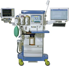
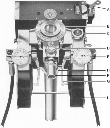
The equipment for the delivery of nitrous oxide-oxygen (N2O-O2) inhalation sedation is quite simple. Primary equipment consists of a supply of the gases and an apparatus for their delivery to the patient. The modern inhalation sedation unit is a compact, continuous-flow machine used for the administration of compressed gases under controlled conditions. This sedation unit is a modification of the machines used to administer inhalation general anesthesia. These machines (Figure 14-1) are capable of delivering a number of inhalation anesthetics, whereas the inhalation sedation unit has been altered to deliver only two gases: N2O and O2.
TYPES OF INHALATION SEDATION UNITS
Demand-Flow Units
The demand-flow type of N2O-O2 inhalation sedation unit (Figure 14-2) does not deliver gas continuously to the patient, but varies the rate and volume of delivered gas according to the patient’s respiratory demands and requirements. In this sense, the demand-flow type of inhalation sedation unit may be compared with the face mask employed by scuba (self-contained underwater breathing apparatus) divers, which operates on the same principle. A major advantage of the demand-flow type of unit is the economy obtained from the decreased volume of compressed gases used.
In operation the gases delivered are proportioned by the machine. Only one dial, which changes the percentages of gases delivered, need be adjusted. This dial provides a direct indication of the percentage of O2 delivered in the mixture (the remainder of gas is N2O). The mechanism involved in the demand-flow unit is much more complex than the flowmeter and in clinical practice has been subject to a greater percentage of error. Demand-flow units show only what was set, not what is actually delivered. If a discrepancy develops between the dial and the actual gas flow, there is no warning while the unit is in operation.1
A second disadvantage of the demand-flow unit is the lack of accuracy of the mixer valve. The percentage of gas delivered is not accurate over the full range of delivery (0% to 100% N2O). Gauert and Husted2 and Allen3 demonstrated the lack of accuracy of two demand-flow units, the McKesson Nargraf and Narmatic. At an indicated O2 percentage of 75%, the actual delivered O2 percentage ranged from 80% to 45%, whereas at 50% indicated O2, the actual delivered percentage ranged from 75% to 22%. Having to rely on a mixer valve that is inaccurate in a machine in which the flow of the individual gases cannot be visualized provides two significant disadvantages to the use of demand-flow units.
The gas circuit followed by the N2O and O2 in the demand-flow machine is as follows:
Clinical examples of demand-flow inhalation sedation-anesthesia units include the following:
Allen has stated that fatalities have resulted from misunderstanding the use of the demand-flow machine.3 In light of this and the distinct advantages of the continuous-flow machines, primarily their greater accuracy and that the flow of gases can be visualized, demand-flow inhalation sedation units are obsolete and their use falls below the standard of care. A demand-flow unit known as Nitronox is used in the hospital and ambulatory setting. This demand-flow unit is unique in that the percentage is not adjustable (fixed at 50/50, O2 and N2O) and extremely accurate. Within the practice of dentistry as practiced in the United States, this type of unit would fall below the standard of care because it prevents the important practice of titration from occurring.
Continuous-Flow Units
The gas circuit used in the typical continuous-flow unit consists of the following:
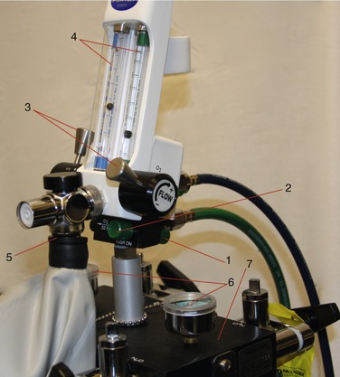
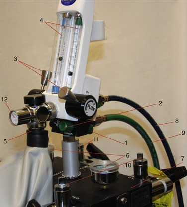
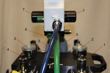
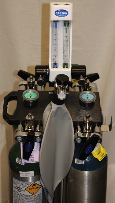
All inhalation sedation units contain the same basic components (see Figures 14-3 to 14-5):
Portable System
In the portable system (Figure 14-6), rolling stand compressed-gas cylinders are attached to the inhalation sedation unit at the yoke assembly. This system is used in offices where the frequency of N2O-O2 use is low or in situations in which the expense of a central storage system is prohibitive.
Central Storage System
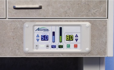
In the central storage system (Figure 14-7), the supply of N2O and O2 is located at a distance from the area in which the gases are delivered to patients. In the treatment area, the inhalation sedation unit (also called the head) will be present along with the accessory equipment required for the delivery of the gases. The head is usually mounted on a wall or bracket. Heads are available in numerous versions from entry level, pneumatic type of systems to modern digital gas delivery systems. Gas cylinders are maintained in a storage area, and gases are delivered to the treatment area through copper pipes. Because these cylinders are stored in a separate location at a distance from the treatment area, larger cylinders are used in the central storage systems. These cylinders are not portable, but they contain significantly more compressed gas than do the smaller cylinders used on portable systems. Multiple treatment areas may be connected through copper piping to this storage area and operated from this bank of cylinders.
Compressed-Gas Cylinders
Gases dispensed at a pressure greater than 25 lb per square inch (25 psig [pounds per square inch gauge pressure]) at 25° C (70° F) are considered compressed gases, according to the hazardous materials regulations of the U.S. Department of Transportation (DOT). Such gases are used in the health professions and in non–health professions (e.g., construction, automobile racing). Because of the potential for serious injury from improper handling of these cylinders, the DOT has promulgated regulations for these gases, some of which are discussed in the following paragraphs.4
All compressed-gas cylinders are tested in accordance with DOT regulations every 5 years to ensure their integrity. Testing is performed by internal hydrostatic pressure, the pressure to which the cylinder is tested based on the size of the cylinder. The shoulder of the cylinder is marked with a metal stamp indicating the date the cylinder was commissioned, dates of testing in accordance with DOT regulations, the pressure for which the cylinder is designed, the insignia of the testing facility, and the identification of the manufacturer of the cylinder (Figure 14-8).
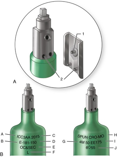
Figure 14-8 A, Pin index safety system prevents accidental crossing of anesthetic gases (see Figures 14-10 and 14-11). B, Compressed-gas cylinders contain much information: A, Interstate Commerce Commission specifications; B, cylinder size; C, maximum working pressure (psi); D, manufacturer’s serial number; E, ownership; F, inspector’s mark; G, manufacturer’s mark and date of original test; H, composition: chrome-molybdenum (steel); I, elastic expansion (ml at 3360 psi); and J, retest dates.
(Redrawn from Dripps RD, Eckenhoff JE, Vandam LD: Introduction to anesthesia, ed 6, Philadelphia, 1982, WB Saunders.)
In addition, the American Society of Anesthesiologists, the American Hospital Association, and the medical gas industry have adopted a uniform color code that is used on all compressed-gas cylinders (Table 14-1). The agents used in inhalation sedation, N2O and O2, are color coded light blue and green, respectively.
| Gas | Coding Color |
|---|---|
| O2 | Green (white—international) |
| N2O | Light blue |
| N2 | Gray bottom, orange shoulder |
| CO2 | Gray |
| Helium | Brown |
The following are important considerations for handling compressed-gas cylinders:
The importance of keeping grease and oil away from compressed gases is so important that additional comment is required. Grease or oil in the presence of a compressed gas forms a potentially explosive mixture. When a cylinder is opened, high-pressure gas (e.g., O2 at 2000 psig) is reduced suddenly to approximately 50 psig and to atmospheric pressure by the reducing valve (see Figure 14-16). Sudden expansion of the compressed gas as it exits the cylinder cools the gas to subzero temperatures. The cylinder valve will become cool, with frost possibly forming. However, almost immediately, as more gas rushes from the cylinder into the restricted space of the reducing valve, both the pressure and temperature are increased. The temperature may increase sufficiently, although only for a few seconds, to ignite any combustible materials that may be present (e.g., grease or oil). Temperatures in excess of 1500° F—well above the ignition temperature of grease or oil—can be produced at this time.
Once the grease or oil ignites, either N2O or O2, although nonflammable, will support combustion. Temperature and pressure within the cylinder increase even further, producing two grave problems: (1) the rapid increase in pressure will soon exceed the limits of the cylinder, leading to an explosion; and (2) as the temperature within the cylinder increases, the valve stem of the cylinder, composed of an alloy with a melting point of 93° C, will melt, thereby releasing the contents of the cylinder. These processes may occur within 1 to 2 seconds. Death and serious injuries to the dentist, staff, and patients have occurred in this manner.5
Compressed-gas cylinders are manufactured in a variety of sizes. They are classified by letter, with the “A” cylinder the smallest and the “HH” the largest (Figure 14-9). In inhalation sedation with N2O-O2, the cylinder sizes used are the “E,” “G,” and “H.” E cylinders are used for both N2O and O2 in portable units, whereas larger cylinders are used in central storage systems—G cylinders for N2O and H cylinders for O2. The physical characteristics of these and other compressed-gas cylinders are compared in Table 14-2, and the gas capacities of the E, G, and H cylinders are compared in Table 14-3.
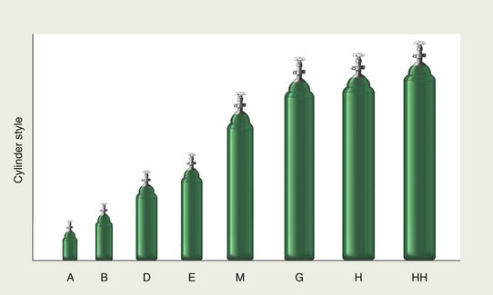
Figure 14-9 Various sizes of compressed-gas cylinders.
(Redrawn from Williams RH: Textbook of endocrinology, ed 6, Philadelphia, 1982, WB Saunders.)
Table 14-2 Characteristics of Compressed-Gas Cylinders
| Cylinder | Dimensions (in) | Weight of Empty Cylinder (lb) |
|---|---|---|
| A | 3.0 × 10 | 2.75 |
| B | 3.5 × 17 | 8 |
| D | 4.25 × 20 | 12 |
| E | 4.25 × 29.5 | 21 |
| M | 7.12 × 46 | 74 |
| G | 8.5 × 55 | 130 |
| H | 9.0 × 55 | 130 |
| HH | 9.25 × 59 | 136 |
Table 14-3 Comparison of E, G, and H Cylinders
| N2O Cylinder Size | E | G |
|---|---|---|
| Dimensions | 4.5 in wide | 8.5 in wide |
| 29.5 in high | 55 in high | |
| 21 lb weight | 130 lb weight | |
| Color of cylinder | Blue | Blue |
| Psi—full | 750-800 | 750-800 |
| Capacity (L) | 159 | 13,839 |
| (gal) | 420 | 3200 |
| Physical state of contents | Gas and liquid | Gas and liquid |
| O2 Cylinder Size | E | H |
|---|---|---|
| Dimensions | 4.5 in wide | 9 in wide |
| 29.5 in high | 55 in high | |
| 21 lb weight | 130 lb weight | |
| Color of cylinder | Green | Green |
| Psi—full | 2000 | 2200 |
| Capacity (L) | 625 | 6909 |
| (gal) | 165 | 1400 |
| Physical state of contents | Gas | Gas |
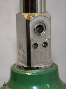
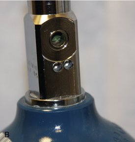
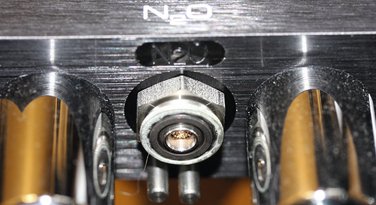
Safety features incorporated in the compressed-gas cylinders include color coding (N2O, blue; O2, green) and the pin index safety system (see Figure 14-33). The pin index safety system is designed so that it becomes physically impossible for an N2O cylinder to be inadvertently attached to the O2 portion of the delivery system and vice versa. This is achieved through a series of holes in the stem of the cylinder that have a unique configuration permitting attachment only to the correct yoke on the sedation unit. Figure 14-10 illustrates the pin index safety system for N2O and O2. The large hole on the top of the stem is the orifice through which the compressed gas exits the cylinder. The two holes beneath the orifice accept pins found on the yoke of the sedation machine. They are countersunk approximately 0.25 inch. On the yoke of the inhalation sedation unit are found pins that will permit the attachment of the appropriate compressed-gas cylinder (Figure 14-11). These pins are welded into the unit. The pin index safety system is designed to prevent the inadvertent attachment of a gas cylinder to the wrong yoke and thus the accidental delivery of 100% N2O when 100% O2 is desired, a situation with potentially catastrophic consequences. Errors have been noted in pin indexing of cylinders.6,7 Careful checking of all compressed-gas cylinders before their use is essential to safety.
Oxygen Cylinder and Contents
O2 in a compressed-gas cylinder is present in a gaseous state. The gas pressure in a full E cylinder is approximately 1900 psig8 at 70° F (25° C) (Figure 14-12, A), whereas the pressure within the larger H cylinder is approximately 2200 psig.9 O2 cylinders are color coded green in the United States and white internationally. One ounce of O2 liquid is equivalent to 5.22 gal of O2 gas.
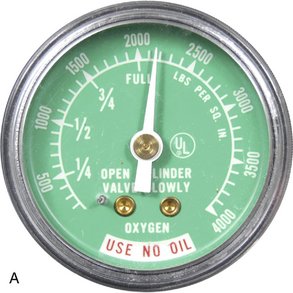
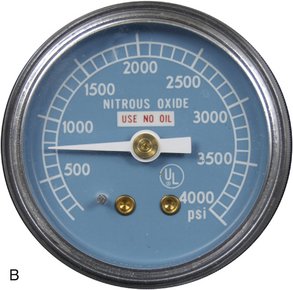
Figure 14-12 Pressure gauges on inhalation sedation unit. A, O2 pressure gauge. B, N2O pressure gauge.
(From Darby ML, Walsh MM: Dental hygiene: theory and practice, ed 3, St Louis, Saunders, 2010.)
Because the O2 cylinder contains only gas, the pressure gauge on the machine yoke reflects the actual contents of the cylinder. In other words, as O2 leaves the cylinder, the pressure within the cylinder will drop accordingly. Therefore if an O2 cylinder records a pressure of 1000 psig (Figure 14-13), the cylinder is 1000/1900, or 52% full. A full E cylinder of O2 will produce 660 L of gaseous O2. At a flow rate of 6 L/min, this tank would empty in 110 minutes (660/6 = 110 minutes). This is an important factor in the safety of inhalation sedation because if an O2 cylinder became empty during a procedure while the N2O cylinder still contained gas, it would be potentially possible to administer 100% N2O. Although there are additional safety features designed to prevent this occurrence, the administrator of the N2O-O2 can see the “fuel gauge” for the O2, and this permits a new cylinder to be opened before the nearly empty cylinder is depleted. If the sedation machine is equ/>
Stay updated, free dental videos. Join our Telegram channel

VIDEdental - Online dental courses


 -inch thick steel. Some cylinders of N2O have been made from aluminum.