14
Electronic Apex Locators and Conventional Radiograph in Working Length Measurement
Introduction
The success of endodontic treatment is highly dependent on the adequate three-dimensional cleaning, shaping, disinfection, and obturation of the root canal system. It is universally accepted that the correct determination of the working length (WL) is one of the crucial steps in the process of a successful treatment.
It is believed that root canal preparation and filling should be kept inside the root canal system to prevent damage to the periradicular tissues. On the other hand, selecting a point shorter than apical constriction may leave infected tissue apically, which may cause the persistence of the disease (Schilder, 1967; Seltzer et al., 1969).
The glossary of endodontic terminology of the American Association of Endodontists (American Association of Endodontists 2003) defines the WL as “the distance from a coronal reference point to the point at which canal preparation and obturation should terminate.”
In order to define an apical end point during a course of root canal therapy, it is imperative to know the anatomy of the apical portion of the root. Several anatomical landmarks exist at the apical segment of each root (Figure 14.1; Table 14.1).
Figure 14.1 Anatomy of the apex of the root.
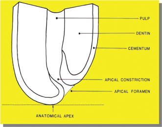
Table 14.1 Some definitions from Glossary of Endodontic Terms (2003).
| Anatomy of the apical section | Definition |
| Anatomic apex | The tip or end of the root as determined morphologically |
| Apical foramen or major foramen | The main apical opening of the root canal. |
| Apical constriction or minor foramen (minor apical diameter, minor diameter) | The apical portion of the root canal having the narrowest diameter; position may vary but is usually 0.5–1.0 mm short of the center of the apical foramen. |
| Cementodentinal junction (CDJ) | The region at which the dentin and cementum are united commonly. Its position can range from 0.5–3.0 mm from the anatomic apex. |
| Radiographic apex | The tip or end of the root as determined radiographically; its location can vary from the anatomical apex due to root morphology and distortion of the radiographic image. |
Traditionally, radiographic images were extensively used to help locate the apical end of the roots. The radiographic apex, which was believed to commonly coincide with apical foramen and was easy to detect radiographically, was considered as the end of the root canal. However, several investigators (Green, 1956, 1960; Kuttler, 1955; Pineda and Kuttler, 1972) have shown that less than 50% of the time, the apical foramen coincides with the anatomical apex (Figure 14.1). Such variations are not easily detectable in two-dimensional radiography, even with minimum distortion. Therefore, considering the radiographic apex as the terminus seems not ideal. Although two different anatomical entities, traditionally, the apical constriction is known as the cementodentinal junction (CDJ) (Grove, 1928, 1930; Kuttler, 1958). However; the location of the apical constriction that coincides with CDJ is known to be variable (Dummer et al., 1984). The apical constriction is easily detectable in histological sections. It is a challenge to detect it clinically or radiologically. Moreover, the apical constriction varies in its topography. It has been classified into simple, diverging, multiple, and parallel constrictions (Dummer et al., 1984). According to these findings it may be concluded that the constriction and its position differ not only in form but also in their presence within root canal space as an anatomical reference.
The majority of the endodontists and clinicians would agree that the apical constriction or minor foramen is where the apical end of the root canal preparation and filling should terminate. The rationale is that minor foramen is the narrowest section of the canal close to the apex with the minimum blood supply where the pulp tissue and the periodontal ligament (PDL) meet and that during root canal treatment, it provides the smallest wound site which is the most favorable for healing (Ricucci and Langeland, 1998).
WL Measurement Methods
Several methods have been used to determine the WL: (1) knowledge of anatomy and average root canal lengths, (2) apical sensitivity reported by patient when the instrument passes through the apical foramen, (3) tactile sensation of the apical constriction with endodontic file, (4) bleeding point as detected by the use of paper points showing bleeding in the most apical portion of the canal, and (5) radiographic technique by using an endodontic instrument within the root canal.
Most of these methods have some limitations and are not sufficiently reliable to be considered as the main measuring technique. Teeth lengths are variable. Apical sensitivity may be absent due to the use of local anesthetic. The tactile sensation of the apical constriction depends on countless factors (Palmer et al., 1971); for example, it might be only helpful in detection of the apical constriction in less than 60% of the cases (Seidberg et al., 1975). An incorrect radiographic technique can cause major distortion of the image (Vande Voorde and Bjorndahl, 1969).
Radiographic Technique
Grove explained that using radiographic technique in the determination of WL is achieved by insertion of an endodontic instrument, usually a file, into the canal to a predetermined length, using a table showing the average length of each of the teeth and taking a radiograph and then adjusting the length as required (Grove, 1928, 1930). This method also has been described in detail by Ingle (1957), and it has been reported to be considered as the most successful method of WL determination compared to the other techniques available to that date (Bramante and Berbert, 1974).
Limitations with Radiographic Technique
Although the radiographic technique is considered the traditional technique and is still used for determining the WL, it has several limitations.
The rationale for using this technique is based on the suggestion that the apical constriction may be located at 1 mm short of the radiographic apex. However; it is not all inclusive, and in some cases, the apical foramen can even be located as far as 3 mm short of the radiographic apex (Kuttler, 1955; Pineda and Kuttler, 1972).
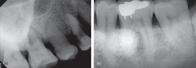
It provides only a two-dimensional image of a three-dimensional object. It is also technique sensitive and relies entirely on the experience of the operator. Variables such as radiographic technique, angulations, inadequate radiographic exposure, will result in distorted or completely useless radiographic images (Figure 14.2). It is sometimes necessary to take several radiographs that will expose the patient to the unnecessary radiation levels; for example, identification of buccal and lingual canals may be challenging because of superimposition of those over each other in a radiographic straight angle image (Figure 14.3a,b). The interpretation of the radiographic image can also be very subjective and an important factor in accuracy of the technique. The radiographic technique provides a two-dimensional image which is subject to error, and some anatomical landmarks could be superimposed on each other, for example, the superimposition of the zygomatic arch over the roots of maxillary molars or mandibular torus over the roots of mandibular premolars (Figure 14.4a,b), which impede the proper location of the radiographic apex on those teeth. The zygomatic arch has been reported to be superimposed in approximately 20% and 42% on the apices of the first and second maxillary molars, respectively (Tamse et al., 1980). The presence of apical resorption can also create a problem for adequate WL measurement using this technique. Based on the fact that root resorption can alter the apical constriction, Weine (2004) suggested subtracting an extra 0.5 mm from the WL in teeth exhibiting radiographic evidence of apical resorption. This may ensure that both the instrumentation and filling materials will be kept confined within the root canal space.
Figure 14.2 Distorted radiograph, elongated image.
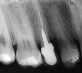
Figure 14.3 (a) Superimposed files over each other in buccal and palatal canals. (b) The same image taken from another angle to see the files separately.
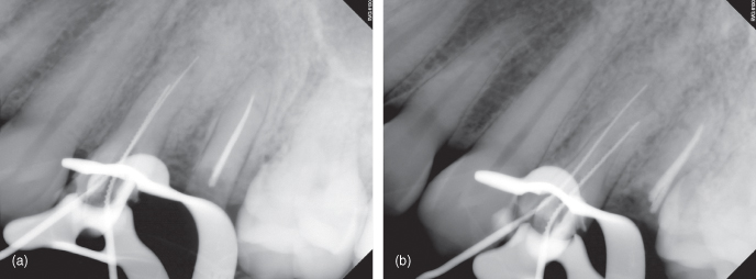
Figure 14.4 (a) Superimposition of the zygomatic arch over the roots of maxillary molars. (b) Superimposition of the Torus Mandibularis over the roots of mandibular premolars.
History of Apex Locators
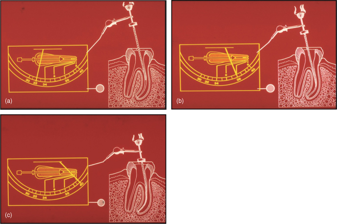
The idea of using electronic locators was born when Custer in 1918 used the electric current to measure the length of the root canals. In 1942, Suzuki conducted experiments of iontophoresis with silver nitrate and ammonium in dogs using direct current and discovered that the electrical resistance between the PDL and oral mucosa had a constant value of 6.5 k ohms (Suzuki, 1942). Sunada in 1962 introduced this principle to the clinic area. He postulated that, according to the results obtained by Suzuki, it would be possible to design a device to measure the length of the root canal electronically. He used an ohmmeter with one electrode connected to the oral mucosa and another electrode connected to an endodontic file. As the file moved into the canal, he found that when the tip of the file was just touching the PDL at apical foramen level, the device registered 40 µA regardless of patient age or the shape and length of the tooth (Figure 14.5a–c). With his findings, he explained that it was necessary to pass the file through the apical foramen to obtain accurate measurements. This would eliminate variables that could produce erroneous measurements (Sunada, 1962).
Figure 14.5 (a–c) Graphic images of Sunada electronic apex locator showing WL determination.
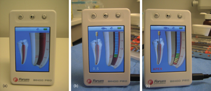
Based on these basic principles, the first apex locators were introduced. In reality, these devices operate using the human body as one of the components to complete the electric circuit. One of the electrodes of the apex locator is connected to an endodontic file while the other is connected through a clip to the labial mucosa of the patient (Figures 14.6 and 14.7). Once the file is inserted into the root canal, the circuit is partially complete, and as the file reaches to the apex, then the electric circuit is completed, and the exact position of the apical foramen is located (Pilot and Pitts, 1997) (Figure 14.8a–c).
Figure 14.6 Lip and file clips.
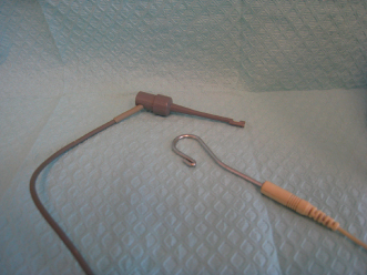
Figure 14.7 Clinical picture of the use of the apex locator.
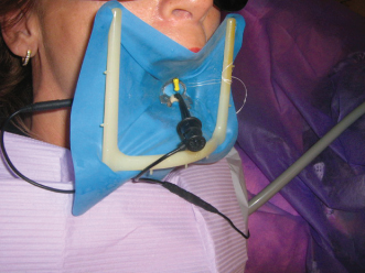
Figure 14.8 Clinical use of Bingo electronic apex locator. (a) Before. (b) At working length. (c) Beyond the working length.
The first generation of apex locators used direct current. Unfortunately, they were very inaccurate and unpredictable. Therefore, in 1969, the Japanese medical company Onuki designed a device that used alternating current. This apex locator was called Root Canal Meter and worked at a frequency of 150 Hz. Today, it is speculated that these devices primarily measure impedance of the electrode; therefore, electrolytic substances as sodium hypochlorite cause erroneous measurements when using these devices (Kobayashi, 1997). As the technology was advancing, new appliances appeared on the market. Some used the detection of changes in electrical frequency for measuring the root canals; others used the voltage gradient method. However, the presence of electrolytes within the root canals prevents proper operation of all these devices. A significant breakthrough was achieved with the introduction of a new generation of the apex locators. This third generation of electronic apex locators (EALs) such as Endex calculates the difference between two electrical impedances in the canal, using an alternating current composed of two different frequencies. This apex locator can accurately measure the length of the root canals even in the presence of electrolytes (Fouad et al., 1993). It is reported that the Endex can find the apical foramen in more than 90% of the cases (Frank and Torabinejad, 1993).
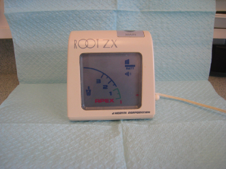
In 1991, the EALs that worked based on “the ratio method” were introduced. These apex locators were not affected by the presence of electrolytes in the canals. In this method, EALs work in such a way that if there is an electrolyte in the canal, two impedances are measured simultaneously by two electric currents with different frequencies. Thus, if one of the impedances changes because of the presence of electrolyte in the canal, the second impedance also changes in the same proportion. Therefore, the ratio between the two frequencies is not affected even in the presence of electrolytes (Kobayashi, 1997). The Root ZX (Morita Japan) is designed based on this principle (Figure 14.9). This device has the advantage of not having to be calibrated for each patient and makes it one of the most efficient and versatile to use. Clinical studies demonstrate its accuracy by 96% of cases (Shabahang et al., 1996).
Figure 14.9 Root ZX electronic apex locator.
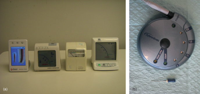
All apex locators are equipped with a display screen or some indicators and a type of alarm that visually and audibly indicate both the proximity and the location of the apical foramen (Figure 14.10a,b).
Figure 14.10 (a) Four different types of electronic apex locators from left to right: Bingo, Root ZX, Osada APIT, Root ZX II. (b) Sybron Endo Mini Apex Locator next to a 21 mm H-file.
Different studies have resulted in an accuracy of between 8% and 94% (Fouad et al., 1993; Frank and Torabinejad, 1993). Shabahang et al. (1996) found that the Root ZX could locate the apical foramen with a tolerance of ±0.5 mm in vital teeth, in 96.2% of the time. Ibarrola et al. (1999) concluded that if the canals are widened before using the apex locator, the results are more consistent. Pagavino et al. (1998) found that the Root ZX could find the apical foramen in 100% of cases, with a tolerance of ±1 mm. Saad and al-Nazhan (2000) suggest using apex locators in conjunction with digital radiovisiography to help reduce the amount of radiation. They only recommend taking a digital radiograph with the master cone in the canal, after having determined the WL electronically.
Clinical Technique
Different operators may use the apex locators slightly differently. Hence, a common technique has only been described here. But the concept of using the apex locator stays the same.
Routinely, regular endodontic therapy procedures usually start with anesthetizing the region and rubber dam isolation. Then an access cavity is prepared, the pulp tissue is removed from the chamber, and the canal orifices are located then the chamber and the canals are irrigated with hypochlorite solution. Then a small K-file No 8 or 10 is introduced into the canal until it reaches the estimated working length (EWL) based on the predetermination using the preoperative radiograph. The files can also be intro/>
Stay updated, free dental videos. Join our Telegram channel
VIDEdental - Online dental courses


