CHAPTER 13
Mandibular Fractures
Christopher J. Haggerty
Private Practice, Lakewood Oral and Maxillofacial Surgery Specialists, Lees Summit; and Department of Oral and Maxillofacial Surgery, University of Missouri–Kansas City, Kansas City, Missouri, USA
Surgical Management of Anterior Mandibular Fractures (Symphysis and Parasymphysis)
Indications for Open Reduction of Anterior Mandibular Fractures
- When closed reduction will not adequately reduce fractures
- When the fixation of anterior mandibular fractures will allow for alignment of other fractures (condyle or angle fracture)
- In order to allow for early mobilization of condylar fractures
- Patients who cannot tolerate maxillomandibular fixation (MMF)
See Figure 13.13 for a comparison of regions of dentate mandible fractures.
Contraindications for Open Reduction of Anterior Mandibular Fractures
- Fractures that can be reduced with MMF alone
Intraoral Surgical Approach and Open Reduction of the Anterior Mandible
- The patient is nasally intubated to allow for the placement of MMF. The endotracheal tube is secured, a throat packing is placed, and the patient is prepped and draped in a sterile fashion.
- Maxillary and mandibular Erich arch bars are adapted and secured in place with either 24- or 26-gauge stainless steel circumdental wires placed below the cingulums of the dentition from first molar to first molar or SMARTLock Hybrid MMF (Stryker, Kalamazoo, Michigan, USA) may be utilized. If Erich arch bars are placed, the incisors may be linked together or abstained if sufficient occlusion results without their incorporation into the arch bars.
- Local anesthesia containing a vasoconstrictor is injected within the anterior mandibular vestibule to include the mentalis muscle.
- A mucosal incision is created with sharp scissors, cautery, or a blade (see Figure 13.3 in Case Report 13.1). The mucosal incision is created parallel to the attached gingiva and approximately 15 mm lateral to the attached gingiva.
- The mentalis muscle and periosteum are transversed between the canines with sharp scissors, cautery, or a blade.
- The mental foramen and nerves are identified with blunt dissection with a fine hemostat within the premolar region. Care is taken to spread the hemostat tines parallel to the anticipated course of the mental nerve. Alternatively, a periosteal elevator can be used to dissect in a subperiosteal plane posterior to the original dissection to locate the mental foramen. Once the mental nerves have been identified, they are dissected free from their surrounding tissue and retracted from the operating site with gentle superior traction.
- The fracture is aligned with a periosteal elevator, and the patient is placed into MMF with 24– or 26-gauge stainless steel wires and/or heavy elastics. If necessary, the fracture can be temporarily reduced with bone-reducing forceps (Figure 13.5, Case Report 13.1), a 24-gauge intraosseous wire, or a small bone plate.
- The well-reduced fracture is internally fixated with lag screws (Figures 13.8 and 13.9, Case Report 13.1; see also Figure 13.1), tension plates (Figures 13.11 and 13.12, Case Report 13.1), or a combination of the two. Care is taken to ensure that the fixation plates and screws are placed a safe distance from the apices of the teeth, the inferior alveolar nerve, and the mental foramen.
- Once internal fixation is applied, the bone-reducing forceps (if utilized) are removed, MMF wires and elastics are removed, and the occlusion is verified.
- Any changes in the patient’s occlusion should be addressed by removing the fixation, identifying areas of interference, and refixating the mandible.
- Once the ideal pre-trauma occlusion has been verified, the incision site is irrigated and closed in a layered fashion.
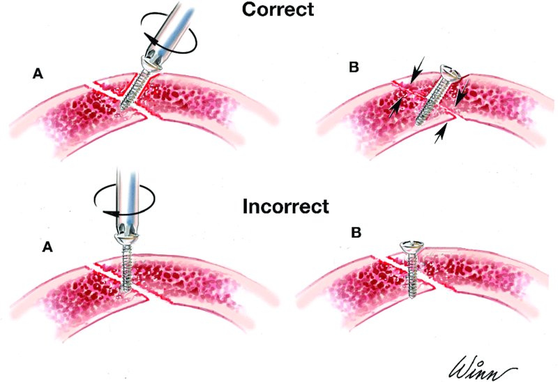
Figure 13.1. Illustration depicting the appropriate and inappropriate placement of lag screws. Note that the gliding osteotomy is larger than the traction osteotomy.

Figure 13.2. Orthopantomogram demonstrating a linear fracture through the mandibular symphysis.
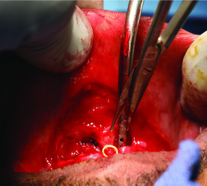
Figure 13.3. Dissection through the mucosa and mentalis muscle with sharp scissors. A finger is placed on the outer lip for support and to detect flap thickness to prevent accidental skin perforation.
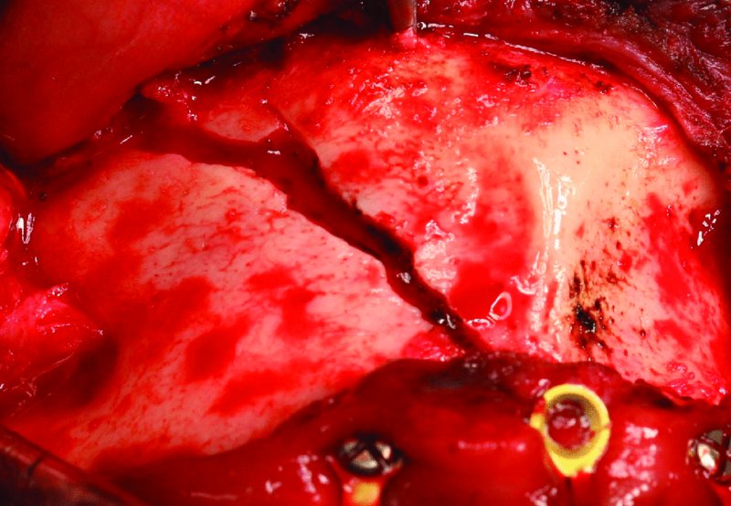
Figure 13.4. Subperiosteal exposure of the anterior mandibular fracture.
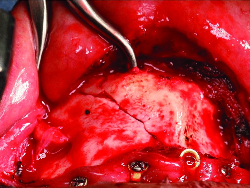
Figure 13.5. Bone reduction forceps are placed at the inferior border of the mandible to reduce the fracture prior to internal fixation.
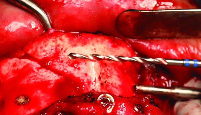
Figure 13.6. The 2.4 mm drill bit is used prior to drilling to estimate the angle and depth of the gliding osteotomy. The cautery was used to create a burn mark to aim for during the preparation of the gliding and traction osteotomy.
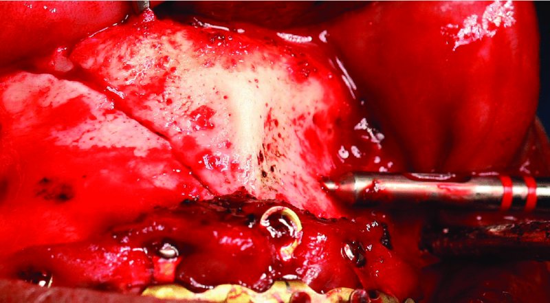
Figure 13.7. The specialized drill sleeve for the 1.8 mm drill bit is inserted internally into the gliding osteotomy to allow for controlled drilling through the distal cortex (traction osteotomy).
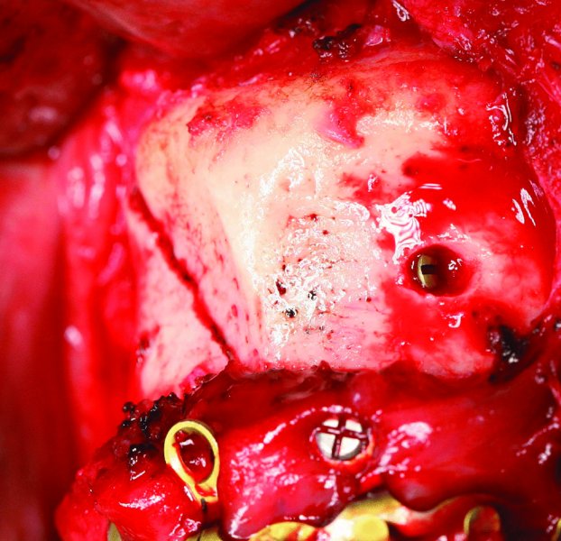
Figure 13.8. As the lag screw engages the contralateral aspect of the fracture, the fracture compresses and reduces. The gliding osteotomy is countersunk slightly.
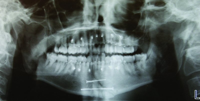
Figure 13.9. Postoperative orthopantomogram demonstrating Stryker SMARTLock Hybrid MMF and the ideal reduction of the linear symphysis fracture with lag screw internal fixation.
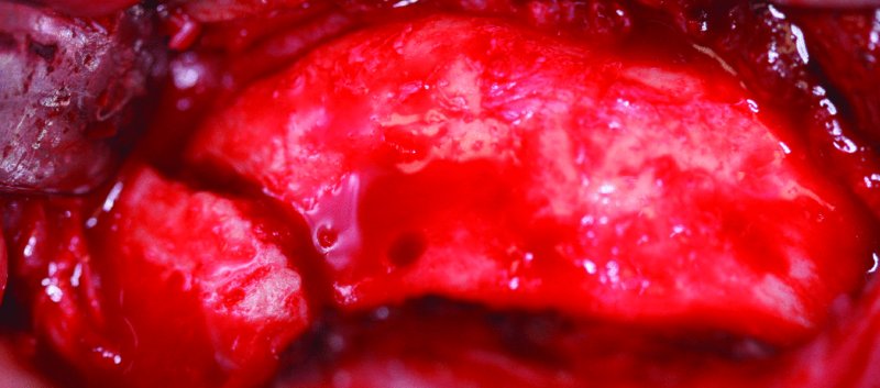
Figure 13.10. Displaced left parasymphysis fracture of the mandible.
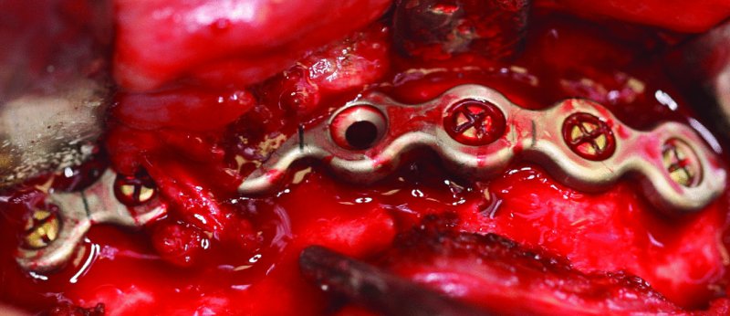
Figure 13.11. Appropriate adaptation and placement of a 2.8 mm reconstruction plate to the inferior border of the anterior mandible inferior to the mental foramen. The empty plate hole represents the site of the reduced left parasymphysis fracture.
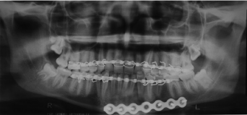
Figure 13.12. Postoperative orthopantomogram showing a well reduced left parasymphysis fracture with appropriate inferior border plate adaptation.
Postoperative Management
- A supportive dressing may be applied to the chin and submental area to provide superior support of the mentalis muscle and to act as a pressure dressing.
- Arch bar removal and functioning are based upon the surgeon’s preferences, the degree of fixation, patient compliance, and the management or fixation of more proximal fractures of the mandible.
Complications
- Ptotic chin (witch’s chin): From inadequate closure of the mentalis muscle.
- Lip perforation: From inadvertent perforation of the anterior lip during dissection to the inferior border of the anterior mandible. Minimized by placing the nondominant hand on the outer surface of the lip to detect the level of dissection.
Key Points
- By placing the mucosal incision 15 mm of more lateral from the attached gingiva, it will permit a sufficient mucosal edge for easy closure, especially in the area of the arch bar.
- Initial dissection should not extend beyond the canines until the location of the mental foramen and mental nerves have been verified.
- Appropriate closure of the mentalis muscle can prevent the formation of a ptotic chin (witch’s chin), asymmetrical muscle contraction, or dimple formation from placing the deep sutures too superficially.
- If other mandibular fractures are present (body, angle, and/or condyle), the anterior mandible fractures are typically fixated first.
- The final step prior to closing any mandible fracture is the verification of the patient’s occlusion.
Procedure: Lag Screw Fixation
A form of compression osteosynthesis commonly utilized in the symphysis and parasympysis region
Indications
- Linear mandibular fractures
- Fractures within the symphyis and parasympysis region (although lag screws can be placed in other locations)
Contraindications
- Oblique fractures
- Comminuted fractures
- Atrophic, edentulous mandibular fractures
- Patients with diminished or poor bone quality
Technique
- Maxillary and mandibular arch bars are placed, and the anterior mandible is exposed from an intraoral approach (Figure 13.3 [all figures in this list appear in Case Report 13.1]).
- The anterior mandibular fracture is aligned and reduced with a periosteal elevator and MMF is applied with 24 or 26-gauge wires and/or heavy elastics.
- Bone reduction forceps may be placed within an area that will not interfere with the placement of the lag screws (Figure 13.5).
- A gliding osteotomy is created. A 2.4 mm drill bit is oriented so that a 30–45 mm screw may be placed perpendicular to the linear fracture. The 2.4 mm drill bit is then drilled to the fracture site (Figure 13.6).
- A traction osteotomy is created. A drill sleeve is inserted that enters the previous drill site (gliding osteotomy). A 1.8 mm drill bit is utilized to drill distal to the fracture until it exits the cortical bone perpendicular to the linear fracture (Figure 13.7).
- The gliding osteotomy is countersunk, and the depth of the osteotomy is measured.
- An appropriate-length screw is placed through the gliding osteotomy, and the traction osteotomy is engaged.
- As the traction osteotomy is engaged with the lag screw, the fracture site will further compress and reduce (Figure 13.8). If the lag screw does not engage the traction osteotomy ideally, the fracture will become displaced as the lag screw is tightened.
- An adjacent lag screw is placed in a similar fashion. The second lag screw may course either in the same direction or in the opposite direction (Figure 13.9) of the first lag screw.
- MMF is removed, and the occlusion is verified prior to closing of the incision in a layered fashion.
Key Points
- Lag screw fixation has a lower incidence of infection and wound dehiscence when compared to plate fixation.
- When drilling the traction osteotomy, make sure to keep the 1.8 mm drill bit as perpendicular as possible to avoid flexing and fracture of the drill bit and to allow for compression perpendicular to the fracture.
- After the placement of lag screw fixation, it is important to exam the lingual aspect of the anterior mandible to ensure that the lingual plate is not splayed. This can be performed by a combination of a conservative dissection of the lingual plate from the inferior border of the mandible and/or by running a finger along the lingual plate after MMF has been removed.
- Fracture selection is paramount in lag screw placement. Ideal fractures include noncomminuted, linear fractures in dentate patients.
References
- Ellis, E., 1998. Lag screw fixation of mandibular fractures. Journal of Cranio-Maxillofacial Trauma, 3, 27.
- Ellis, E., 2012. Is lag screw fixation superior to plate fixation to treat fractures of the mandibular symphysis? Journal of Oral and Maxillofacial Surgery, 70, 875.
- Ellis, E. and Ghali, G.E., 1991. Lag screw fixation of anterior mandibular fractures. Journal of Oral and Maxillofacial Surgery, 49, 13.
- Tiwana, P.S., Kushner, G.M. and Alpert, B., 2007. Lag screw fixation of anterior mandibular fractures: a retrospective analysis if intraoperative and postoperative complications. Journal of Oral and Maxillofacial Surgery, 65, 1180.
Surgical Management of Posterior Mandibular Fractures (Body and Angle)
Indication for Open Reduction of Posterior Mandibular Fractures
- Unfavorable fractures
- Displaced fractures that cannot be adequately reduced with closed reduction alone
- Flail jaw
- Contralateral condyle fractures that require early mobilization
- Patients who cannot tolerate closed reduction
- Infected fractures
- Open fractures
- Patients with other facial fractures that will require using the mandible as a base or starting point for establishing the vertical and anterior-posterior dimensions of the midface
Contraindications for Open Reduction of Posterior Mandibular Fractures
- Favorable fractures well reduced with MMF alone
- When damage to the neurovascular bundle is imminent
- Grossly comminuted fractures with bone segments too small to fixate
- Patients with significant comorbidities (e.g., elderly, previous head and neck radiation, or bisphosphonate-induced osteonecrosis of the jaw)
Submandibular Approach Layers
- Skin
- Subcutaneous tissue
- Platysma muscle
- Superficial layer of the deep cervical fascia (SDCF)
- Pterygomasseteric sling
- Periosteum
- Mandible
Anatomy
- Platysma muscle: Paired muscle that originates from the superficial fascia of the pectoral and deltoid muscles and runs obliquely to insert at the corner of the mouth and inferior portion of the cheek.
- Superficial layer of the deep cervical fascia (SDCF): Located just deep to the platysma muscle. This fascial layer encircles the sternocleidomastoid muscle (SCM) and the trapezius muscle. The SDCF forms the capsule overlying the submandibular gland. The SDCF contains the facial artery, the facial vein, the node of Stahr, and the marginal mandibular and cervical branches of the facial nerve.
- Submandibular gland: Located between the anterior and the posterior bellies of the digastric muscle.
- Node of Stahr (submandibular lymph node): Typically encountered in the area of the premasseteric notch. Serves as a warning for the location of the facial artery and vein, which lie just anterior to the node of Stahr.
- Marginal mandibular nerve: Located above the inferior border of the mandible (80%) or within 2 cm below the inferior border (20%). Lies deep of the platysma muscle along its entire course but becomes more superficial 2 cm lateral to the corner of the mouth. Damage to the marginal mandibular nerve results in paralysis of the depressors of the corner of the mouth (depressor labii inferioris, depressor anguli oris, inferior fibers of the orbicularis oris, and the mentalis).
- Cervical nerve: Located inferior to the marginal mandibular nerve and deep to the platysma muscle. Damage to the cervical nerve results in paralysis of the depressor anguli oris and of the platysma muscle.
Intraoral Surgical Approach and Open Reduction of the Posterior Mandible
- The patient is nasally intubated, the endotracheal tube is secured, a throat pack is placed, and the patient is prepped and draped.
- Maxillary and mandibular arch bars are placed.
- Local anesthesia containing a vasoconstrictor is injected within the area of the proposed intraoral incision.
- A bite block is placed on the contralateral side of the posterior mandibular fracture.
- A #15 blade or needle-tip cautery is used to create an incision through mucosa parallel to the mucogingival line. The incision is placed at least 15 mm lateral to the mucogingival line in order to allow for uncomplicated closure of the intraoral incision.
- After mucosal incision, the #15 blade or cautery tip is directed toward the underlying mandible. The submucosa, muscle, and periosteum are sharply transected.
- A periosteal elevator is used to dissect within a subperiosteal plane posterior to the sigmoid notch and anteriorly as far as needed. Attention to the location of the mental foramen and mental nerve is key as the dissection proceeds anteriorly.
- The proximal and distal segments of the fracture are aligned with a periosteal elevator, and the patient is placed into MMF with either 24– or 26–gauge stainless steel wires and/or heavy elastics. If a posterior tooth is located within the line of fracture and if it will not serve as an occlusal reference, it is removed at this time (see Figure 13.15; all figures cited appear in Case Reports 13.3, 13.4, and 13.5).
- If a trocar is indicated, a local anesthesia needle is inserted through the cheek at the desired location of the intraoral trocar site (Figure 13.16). A #15 blade is used to make a skin incision approximately 4–6 mm in length and parallel to the anticipated direction of the facial nerve. The trocar is bluntly inserted from the extraoral incision into the oral cavity (Figure 13.17).
- After fixation of the fracture (Figures 13.18 and 13.21), a curved periosteal elevator is run along the inferior border of the mandible to assess for proper alignment. For angle fractures, a periosteal elevator is also used to evaluate the superior aspect of the lingual plate of the mandible to ensure ideal fracture reduction.
- The patient is removed from MMF, and the occlusion is verified.
- After occlusal verification, the intraoral incision is closed with interrupted or continuous 4-0 chromic or Vicryl sutures. If a trocar incision was created, it is closed with 5-0 interrupted plain gut sutures.
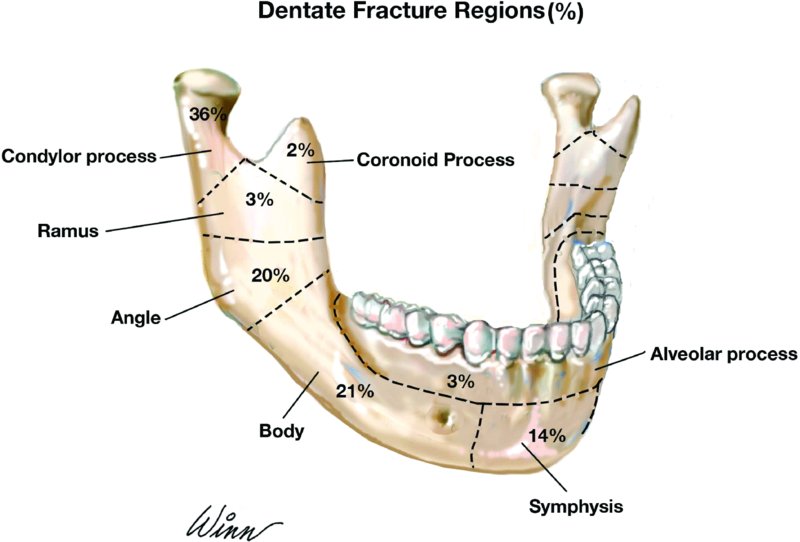
Figure 13.13. Percentage of dentate mandible fractures by region. Modified from Ochs, MW (2008).
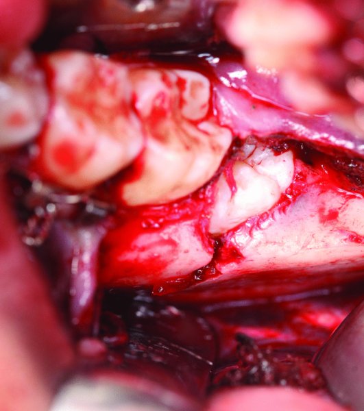
Figure 13.14. Intraoral exposure of the left mandibular angle fracture. The incision was created to incorporate the exposure and extraction of tooth #17 within the line of fracture.
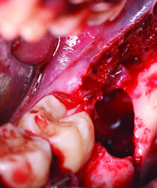
Figure 13.15. Left angle fracture after the extraction of tooth #17. Care was taken to not damage or displace the cortical bone during the extraction.
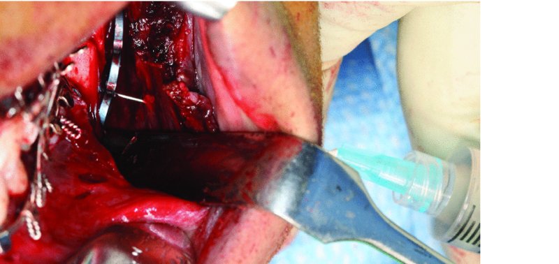
Figure 13.16. Insertion of a local anesthesia needle through the cheek to the oral cavity. By using the local anesthesia needle as a reference, it will allow for the ideal placement of the skin incision and trocar placement.
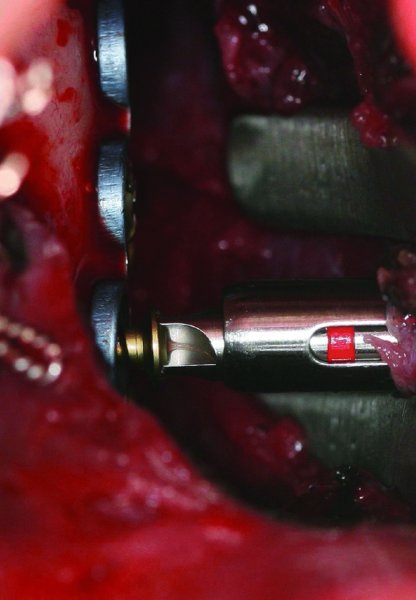
Figure 13.17. Placement of monocortical 2.0 screws through the trocar.
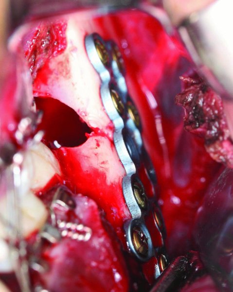
Figure 13.18. Plate secured to the lateral aspect of the posterior mandible with a strut plate and monocortical screws.
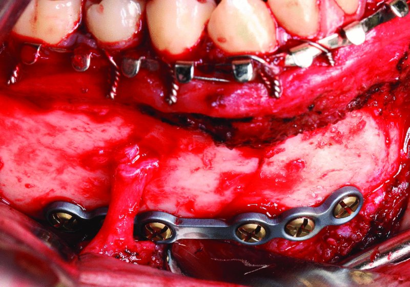
Figure 13.19. Contralateral fracture reduced with six-hole 2.0 plate at the inferior border with bicortical screws.

Figure 13.20. Postoperative orthopantomogram demonstrating fracture reductions.
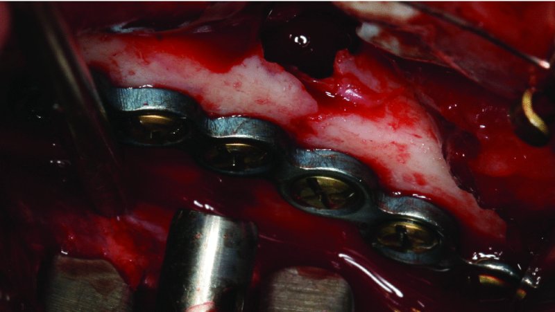
Figure 13.21. Six-hole plate placed at the superior border of the mandibular angle with monocortical screws. Impacted tooth #17 was extracted, and the plate was placed utilizing a percutaneous trocar.
Submandibular Approach and Open Reduction of the Posterior Mandible
- The patient is nasally intubated, the endotracheal tube is secured, and maxillary and mandibular arch bars are placed. Short-acting paralytics are used in order to allow for testing of the facial nerve.
- The patient is prepped and draped. A sterile marking pen is used to mark the site of the proposed skin incision (Figure 13.26).
- Local anesthesia containing a vasoconstrictor is injected within the subcutaneous tissue superficial to the platysma muscle. If local anesthetic is deposited below the platysma muscle, it may paralyze the cervical and marginal mandibular branches of the facial nerve. Alternatively, injection deep to the platysma may be performed with a vasoconstrictor without local anesthetic. Seven to ten minutes are allowed prior to incision for the ideal hemostatic properties of the vasoconstrictor.
- The incision is placed at least 2 cm below the inferior border of the mandible within a neck crease or parallel to a neck crease (Figure 13.26). The incision should allow for direct visualization of the fracture(s) and may extend posteriorly to the mastoid region and anteriorly as far as is needed. The initial incision is carried through skin, subcutaneous tissue, and platysma muscle only.
- The subcutaneous layer is undermined in all directions with a hemostat in order to facilitate a tension-free closure at the end of the procedure.
- Deep to the platysma muscle is the SDCF. The SDCF can be exposed by utilizing a 4 × 4 gauze and digital pressure once the platysma muscle is transected. The marginal mandibular and cervical branches of the facial nerve are located within or just deep to the SDCF.
- A nerve stimulator is set on 2 milliamperes (mA) and tested. Blunt dissection through the SDCF is performed with a pair of fine hemostats and a nerve stimulator (Figure 13.27).
- The submandibular gland is identified. The SDCF forms the investing fascia of the submandibular gland (Figure 13.28). The submandibular gland is retracted inferiorly. The node of Stahr may be encountered within the area of the premasseteric notch and retracted superiorly. The node of Stahr acts as a warning for the proximity of the facial artery.
- Dissection continues cephalically after developing a plane of dissection deep to the SDCF. The pterygomasseteric sling is encountered and is divided at its avascular plane at the inferior border of the angle of the mandible where the masseter and medical pterygoid muscle intersect.
- The periosteum is incised,, and the lateral aspect of the mandible is exposed in a subperiosteal plane (Figure 13.29).
- After fixation of the posterior mandibular fracture (Figure 13.31) and verifying occlusion, closure is performed in the following fashion: the pterygomasseteric sling is tightly approximated with interrupted 3-0 Vicryl sutures, the platysma muscle is closed with 3-0 interrupted or continuous Vicryl sutures, the subcutaneous tissue is closed with interrupted or continuous 4-0 monofilamentous sutures, and the skin is approximated with either steri-strips or 5-0 plain gut sutures (Figure 13.32).
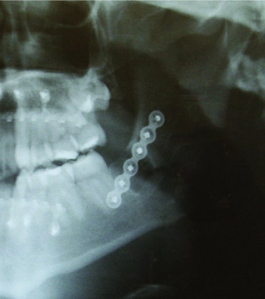
Figure 13.22. Postoperative orthopantomogram showing fracture reduction.
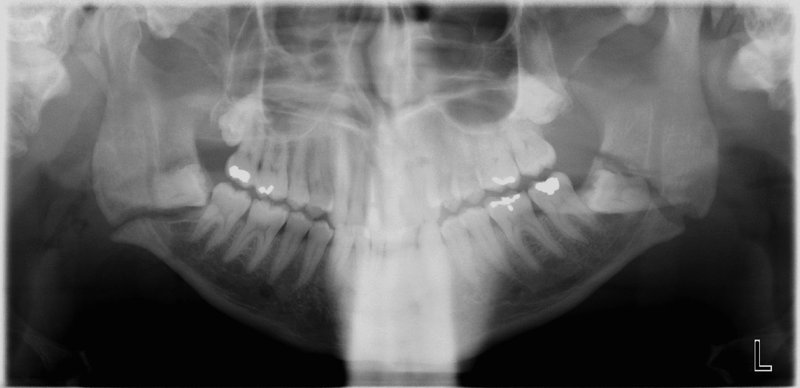
Figure 13.23. Initial presentation of the patient with bilateral mandibular angle fractures with teeth in the line of the fractures.
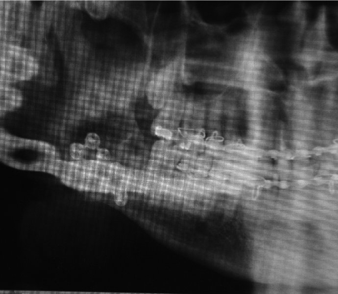
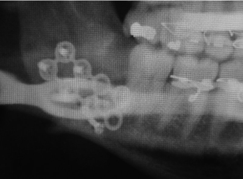
Figure 13.25. Orthopantomogram 2 weeks postoperative demonstrating hardware failure.
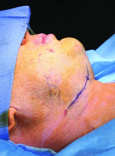
Figure 13.26. Submandibular approach. The skin incision is marked and positioned within an upper cervical crease greater than 2 cm below the inferior border of the mandible.
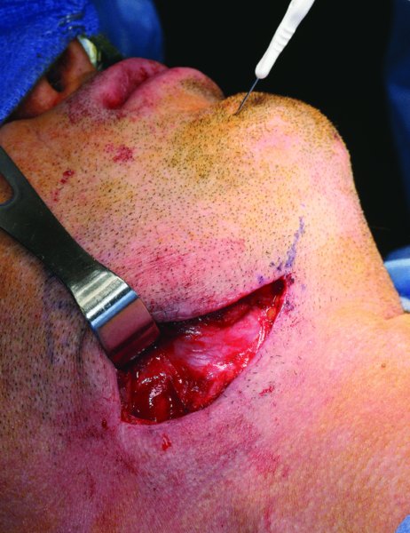
Figure 13.27. Exposure of the superficial layer of the deep cervical fascia (SDCF) and the placement of a nerve stimulator within the soft tissue of the chin. The SDCF contains the marginal mandibular and the cervical nerves.
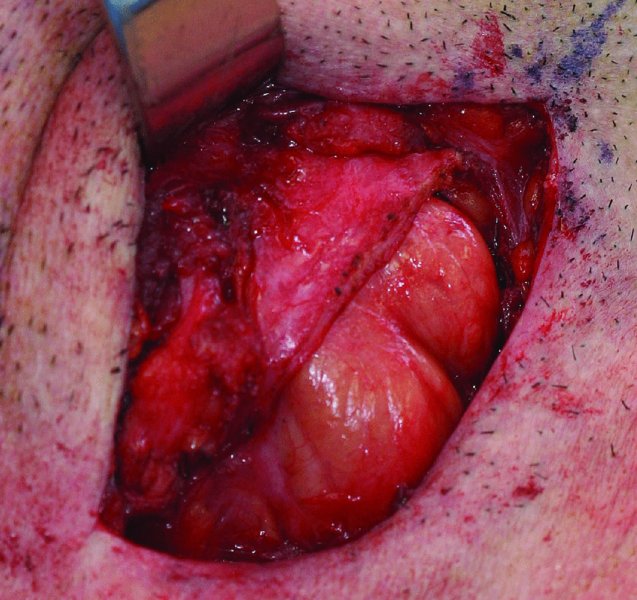
Figure 13.28. Division of the superficial layer of the deep cervical fascia (SDCF) as it courses over the submandibular gland. The marginal mandibular nerve is typically located within the SDCF overlying the submandibular gland.
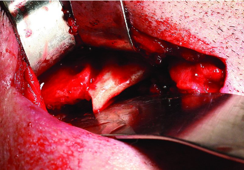
Figure 13.29. The inferior border of the mandible is exposed, the failed hardware is removed and the site is debrided.
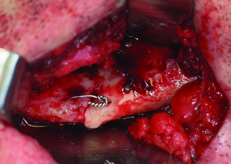
Figure 13.30. Placement of a 24-gauge stainless steel intraosseous wire to align the proximal and distal segments of the fracture prior to the placement of rigid internal fixation.
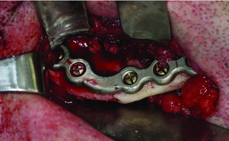
Figure 13.31. Placement of a seven-hole 2.8 mm reconstruction plate at the inferior border of the mandible caudal to the anticipated course of the inferior alveolar nerve.
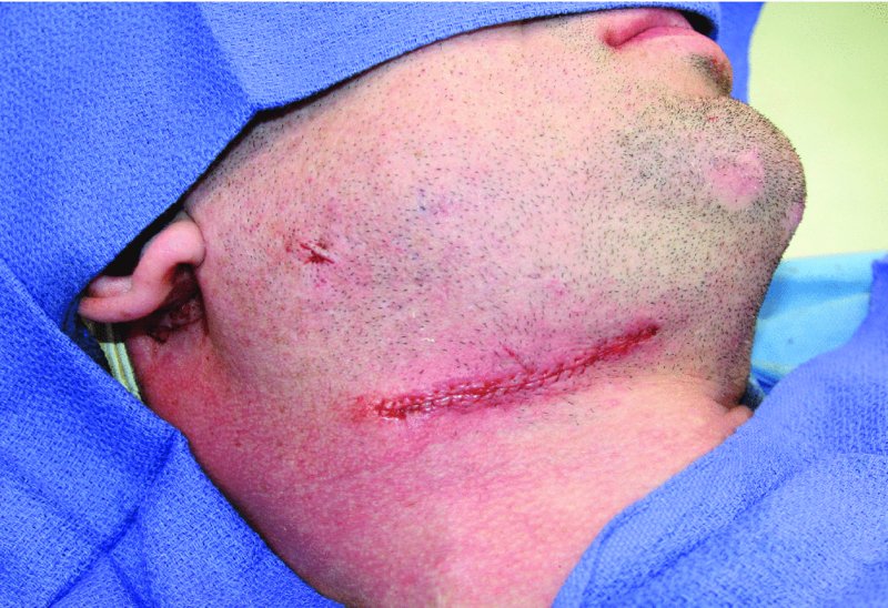
Figure 13.32. Closure of the submandibular and trocar incisions.
Postoperative Management
- Patients are placed into MMF using either stainless steel wires or heavy elastics. The duration of MMF is dependent on the degree of fixation, patient compliance, medical issues (e.g., malnourishment, seizures, or mental handicap), patient age, and other associated fractures (e.g., condyle fractures require earlier mobilization).
- Elastics may be used to place the patient into heavy MMF or to act as guiding elastics to allow for the early limited functioning and muscle reprogramming. Light or guiding elastics are typically reserved for patients with rigid fixation, younger patients, patients with medical issues contraindicating prolonged MMF, and patients with associated condyle fractures.
- Pressure dressings are applied based on the surgeon’s preference.
- Appropriate analgesic and antibiotic coverage is warranted for the first 7 days after surgery. Scopolamine transdermal anti-nausea patches are prescribed for patients in MMF. Nutrition consultation is recommended for all patients discharged with MMF for periods greater than 2 weeks.
- Ice is applied to the fracture site for the first 24 hours.
- Patients with any form of MMF are discharged with either wire cutters or scissors.
- Patients are followed at 1 week, 3 weeks, and 6 weeks after surgery.
- Arch bars are typically removed after 4–6 weeks based on patient exam (occlusion and maximum vertical opening), fixation technique, and compliance.
Complications
- Malocclusion: Caused by failure to appropriately reduce fractures, displaced condyle fractures, inappropriate fixation, or fixation failure. Minor occlusal discrepancies can be corrected with guiding elastic (early) or orthodontics (late). Severe occlusal discrepancies are best treated with reoperation (early) or mandibular osteotomy (late).
- Damage to tooth roots: Caused by placing fixation screws near adjacent teeth roots. Can be minimized by positioning bone reduction plates along the inferior border of the mandible, using monocortical screws, using drills with 4–6 mm stops, and placing screws a minimum of 12 mm inferior to the cementoenamel junction of posterior teeth.
- Hypoesthesia: Can be caused from damage to the mental nerve during fracture exposure or from damage to the inferior alveolar nerve during screw placement. Bicortical screws should only be placed caudal to the mandibular canal. Monocortical screws should be placed along the lateral border of the mandible cephalic to the mandibular canal.
- Facial paralysis: Typically occurs from stretching or transection of the marginal mandibular or cervical nerves during external approaches to the posterior mandible.
- Infection: Infections typically present in the form of wound dehiscence or abscess formation. Infections occur from a variety of reasons. Infections involving hardware should be treated with hardware removal, gross debridement of all nonvital bone and granulation tissue, a period of MMF, and antibiotics. Continuity defects are best treated with grafting procedures after the infection has resolved. Infections can also occur in the areas of teeth left within the line of fracture or from the extraction of teeth within the line fracture (typically third molars). Infections originating from teeth within the line of fracture are treated with tooth extraction and surgical debridement of nonvital bone and granulation tissue and the use of antibiotics. Infections originating from extraction sites are also treated with the removal of nonvital bone and granulation tissue and the use of antibiotics. A short period of MMF is suggested with moderate to severe infections or with fracture mobility.
- Wound dehiscence: Frequently caused by infection, hardware exposure, or smoking abuse. Hardware exposure is initially treated with oral antibiotics and debridement of the site. Areas of hardware exposure that fail to heal after conservative managment or areas with fractured or loose hardware require hardware removal.
- Pseudoarthrosis (non-union) or fibrous union: Typically occur from infection or mobility of the fractured segments. Sources include hardware failure, nonrigid fixation, noncompliance with soft diet or MMF, and underlying medical conditions (diabetes, substance abuse, cigarette abuse, reduced immune system, etc.).
- Malunion: Occurs from inadequate fracture reduction, patient noncompliance, and torsional forces when treating multiple fractures.
- Hardware failure: Hardware fracture can be caused by repeated bending of the plate by the novice surgeon prior to rigid fixation. Loosening of screws is typically caused by improper drilling techniques. Such techniques involve insufficient irrigation, not placing fixation screws perpendicular to the bone reduction plate, and insufficient bone contact when using shorter 4 mm screws. Hardware fracture can also occur from patient noncompliance and additional trauma. All failed hardware should be removed, the site debrided and additional hardware is placed unless sufficient bone union has occurred.
Key Points
- Wisdom teeth in the line of fracture should be removed to minimize postoperative infection.
- Patients with multiple mandibular fractures are plated from anterior to posterior and from rigid to nonrigid fixation. For example, if a patient has sustained a symphysis and an angle fracture, the symphysis is typically plated first with rigid internal fixation, and then the angle is plated with rigid or nonrigid (Champy plate) fixation. If a patient presents with an angle fracture and a condylar fracture, the angle fracture is typically plated first with rigid fixation, and the condylar fracture can be treated closed or with nonrigid or rigid fixation. In the situations discussed here, the more assessable fracture (simpler fracture) is rigidly fixated in order to provide less torsional forces to the more distal (more difficult) fracture. After the application of rigid fixation to the simpler fracture, the more difficult fracture can be treated as if it were an isolated fracture.
- If fracture reduction is non-ideal, it may be necessary to remove MMF, adjust the proximal and distal segments of the fracture site, and then reapply MMF. Sometimes, MMF can lock out the fracture if MMF is applied early on in the procedure.
References
- Ellis, E., 2009. Management of fractures through the angle of the mandible. Oral and Maxillofacial Surgery Clinics of North America, 21, 163.
- Ellis, E., 2010. A prospective study of 3 treatment methods for isolated fractures of the mandibular angle. Journal of Oral and Maxillofacial Surgery, 68, 2743.
- Ellis E., 2013. Open reduction and internal fixation of combined angle and body/symphysis fractures of the mandible: how much fixation is enough? Journal of Oral and Maxillofacial Surgery, 71, 726.
- Fattahi, T., 2006. Surgical anatomy of the mandibular region for reconstructive purposes. Atlas of Oral and Maxillofacial Surgery Clinics of North America, 14, 137.
- Goyal, M., Marya, K. and Chawla, S., 2011. Mandibular osteosynthesis: a comparative evaluation of two different fixation systems using 2.0 mm titanium miniplates and 3-D locking plates. Journal of Oral and Maxillofacial Surgery, 10, 32.
- Luyk, />
Stay updated, free dental videos. Join our Telegram channel
VIDEdental - Online dental courses


