12
Radiographic Imaging in Implant Dentistry
Discussion of this chapter is specifically focused on radiographic imaging of implant therapy for single tooth replacement or for a small partially edentulous span. The key to the successful outcome of implant dentistry is osseointegration. Osseointegration is where vital bone is in direct and intimate contact with the titanium surface of the dental implant (Adell et al., 1981).
Various success criteria have been developed that involve clinical and radiographic findings (Albrektsson et al., 1986; Buser et al., 1990; Mombelli and Lang, 1994). They include:
- No pain, discomfort, altered sensation or infection attributable to the implants
- Individual unattached implants are immobile when tested clinically
- No probing depth greater than 5 mm
- No probing depth of 5 mm with bleeding on probing
- Absence of a continuous radiolucency around the implant
- Mean vertical bone loss is less than 0.2 mm annually following the first year of function.
Osseointegration is a histological and microscopically phenomenon, so clinically, use of radiographs is important in determining the location of the bone in relationship to the implant.
Normal Radiographic Findings Around Dental Implants
Use of periapical and bitewing radiographs is often adequate to assess the quality and quantity of bone around the implants that have been restored and are in function.
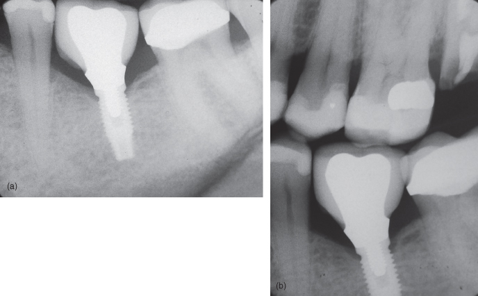
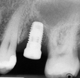
Adequate bone-to-implant contact is indicated by the absence of continuous radiolucency around the implant. With respect to marginal peri-implant bone level, during the first year of function and depending on the type of implant system, bone remodeling may lead to marginal bone loss of 1.5 mm (Adell et al., 1981). This often coincides with the level of the first thread. After the first year, there should be negligible progressive bone loss of less than 0.2 mm annually (Albrektsson et al., 1986) (Figures 12.1a,b and 12.2a,b).
Figure 12.1 (a) Implant with normal bone level. (b) Implant with normal bone level.
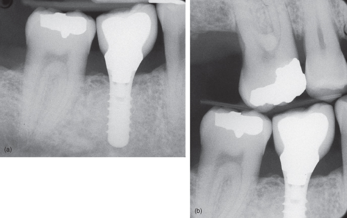
Figure 12.2 (a) Implant with normal bone level; (b) Implant with normal bone level.
Radiographic assessment of implants should be performed annually during the first 3 years by the inexperienced clinician. Afterwards, assessments may be individualized as one gains more clinical experience (Gröndahl and Lekholm, 1997a).
Abnormal Radiographic Findings Around Dental Implants
Abnormal radiographic findings do not necessary mean that the dental implant has failed. However, it does warrant further investigation. A decision as to whether further treatment is needed will depend on the clinical findings and how implant therapy fits in the overall treatment plan.
Often the early signs of implant failure are subtle and may not be visible radiographically. However, if there is peri-implant radiolucency, there is a high positive predictive value of 83% to radiographically identify failing implants. Only 5% of implants were found to be failing without any radiographic evidence (Gröndahl and Lekholm, 1997b) (Figures 12.3a,b–12.6).
Figure 12.3 (a) Implants with bone loss. (b) Implants with bone loss.
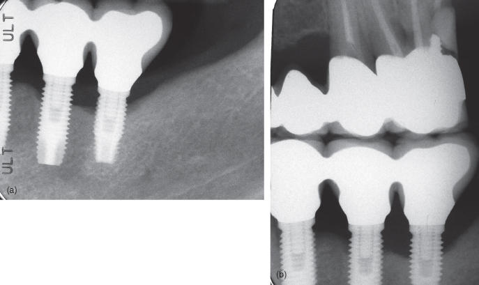
Figure 12.4 Implant with radiolucency on its mesial aspect.
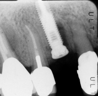
Figure 12.5 Mesial implant has radiolucency on its mesial and apical aspect.
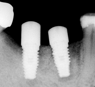
Figure 12.6 Implant with radiolucency on its mesial and distal aspect.
Preoperative Radiographic Planning for Implant Surgery
When planning for surgical placement of dental implants, it is crucial to obtain information on bone volume and quality, topography, and adjacent anatomical structures (nerves, vessels, roots, nasal floor, and sinus cavities). While some information can be gathered by clinical examination, appropriate radiographic imaging is a common clinical task and is one of the most important parameters a practitioner can assess. Therefore, it is considered a prerequisite for preoperative planning in implant treatment (Park, 2010).
The American Academy of Oral and Maxillofacial Radiology (AAOMR) considers complete imaging to reveal information about the following (White et al., 2001):
Standard radiographic imaging techniques in implant dentistry include intraoral, panoramic, and profile (lateral) radiographs. Until the late 1980s, these conventional radiographic techniques have been the accepted standard. Since then, there has been significant development in cross-sectional imaging techniques and in certain special indications, such techniques (i.e., spiral tomography and multiplanar reformatted computed tomography (CT), and cone beam computed tomography [CBCT]) may be necessary. This section will provide a brief overview of the imaging modalities utilized in implant planning, placement, and evaluation for single tooth replacement or small partially edentulous span.
Intraoral Radiography
Periapical Radiography
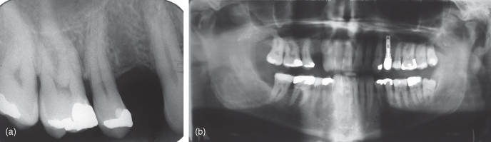
Periapical radiographs are used before, during, and after implant placement and restoration. The periapical radiography is available in all dental practices. The paralleling technique with F-speed film and rectangular collimation with palate or occlusal plane placed horizontally (respectively for maxilla and mandible) is a recommended technique of the acquisition of the radiographic image (Harris et al., 2002) (Figure 12.7a).
Figure 12.7 (a) Periapical radiograph to assess the maxillary first premolar site for an implant—note the mesial curvature of the second premolar that may interfere with implant placement. (b) Panoramic radiograph to assess the maxillary first premolar site for an implant—Overall view of maxilla and mandible—note the location of right maxillary sinus, sinus has no pathology, impacted mandibular wisdom tooth, presence of a dental implant that appears to have an open margin.
A periapical radiograph needs to be positioned as parallel as possible to the long axis of the implant to minimize image distortion and magnification. In this way, a high-quality detailed image with more accurate measurements in both vertical and horizontal directions can be obtained at a very low cost and with a low radiation exposure (associated effective doses of <0.006 mSv per radiograph to the patient) (Harris et al., 2002). Such image can compare well to more advanced cross-sectional imaging techniques (outlined below) for longitudinal and linear distance measurement (Wakoh et al., 2006). A slight vertical angulation of 9 degrees from the long axis of the implant may be necessary for proper bony and inner thread visualization. However, it should be noted that a vertical angle exceeding 13 degrees will cause some overlap of the thread images (Hollender and Rockler, 1980).
In some situations (such as shallow vestibule), intraoral anatomical configurations may interfere with the proper placement of a periapical film apically to image the entire implant. In such cases, two radiographs, including a bite-wing-type projection to assess bone response around the coronal portion and a bisecting angle technique to image the entire length of the implant, is recommended. It should be noted that a bisecting angle projection may obviously exceed the 13 degrees maximum as outlined above (Truhlar et al., 1993). Except in such a particular situation, the use of the bisecting angle technique is discouraged. It should be remembered that with the periapical radiographs, only a limited field of bone/dentition can be imaged and a cross-sectional view of the alveolar process cannot be examined (Wyatt and Pharoah, 1998).
Extraoral Imagining Techniques
Panoramic Radiography
Panoramic radiography has contributed significantly to maxillofacial diagnoses in the last 30 years (Angelopoulos et al., 2008). The panoramic radiography has been used frequently as the first choice of imaging modalities for preimplant evaluation and placement. It is rapid and relatively inexpensive modality used to gain an excellent general overview of the dentition and jaws with minimum radiation exposure to patients (associated effective doses of <0.003 mSv) (Harris et al., 2002). Panoramic radiographs can provide relatively clear images of the jaws due to the correct alignment of the head and teeth (except for edentulous patients) (Wyatt and Pharoah, 1998). However, the accuracy of the image varies greatly with patient positioning. Therefore, in order to avoid positioning artifacts, proper positioning (meato-orbital plane horizontal, head symmetrical, lower jaw protruding, lower and upper incisors inside the image layer and neck extended) is critical (Harris et al., 2002).
Panoramic radiographs can provide basic information on the shape of the jaws and dimension of the bone, and the location and dimension of the important adjacent anatomical structures such as maxillary sinus, nasal cavity floor, inferior alveolar canal, and mental foramen (Figure 12.7b). In additio/>
Stay updated, free dental videos. Join our Telegram channel
VIDEdental - Online dental courses


