Chapter 11
Root canal instrumentation
Introduction
Principles of root canal instrumentation
Root canal instrumentation is accomplished by the use of endodontic instruments and (antimicrobial) irrigants under aseptic working conditions. A primary objective of this chemomechanical preparation, in teeth with either vital or non-vital pulps, is shaping the root canal space. It is generally accepted that the most appropriate final root canal shape is a tapered (conical) preparation with the smallest diameter at the end-point near the root tip, and the widest at the canal entrance. Special attention should therefore be paid to the apical level and the original path of the canal. As a general rule, the removal of root dentin should be centered, i.e. with respect to the initial root canal anatomy. In the process existing soft-tissue elements, serving as potential substrate for growth of remaining microorganisms, will be removed as well.
Root canal instrumentation may be carried out using hand-held or machine-driven (rotary) instruments. These instruments come in many configurations but are conventionally grouped according to ISO (International Organization for Standardization) and ANSI (American National Standards Institute) standards. The quality, sizing and physical properties of endodontic instruments and the materials used for their manufacture are therefore well defined. Instrument properties (e.g. stiffness) relate to type of alloy (stainless steel versus nickel–titanium), degree of taper (conicity) and cross-sectional design.
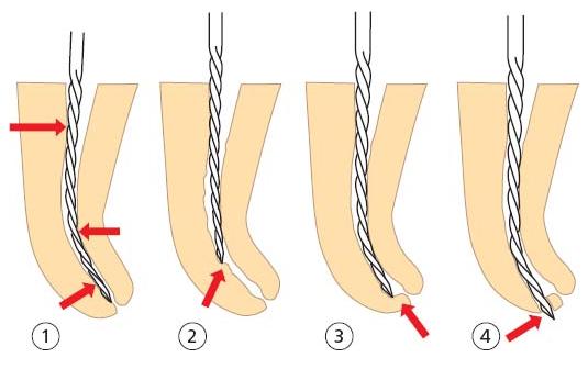
Stainless steel files have a high inherent stiffness that increases with increasing instrument size. As a result, restoring forces attempt to return the instrument to its original shape when preparing a curved root canal, especially when using a filing motion. An instrument that is too stiff will cut more on the convex (outer) side than on the concave (inner) side, thereby straightening the curve (Fig. 11.1). The resulting “hour-glass shape” and canal aberrations (e.g. ledge, zip and perforation) leave an important portion of the root canal wall uninstrumented and create an irregular canal shape that is difficult to clean, disinfect and fill properly.
Over time, researchers and clinicians have found a variety of methods to deal with the stiffness of stainless steel instruments. As a result, various movements for the manipulation of these files and approaches to shape the canal were proposed. While skillful operators can handle these techniques, shaping a curved root canal with stainless steel hand files remains a time-consuming and most challenging exercise.
Besides adaptations in file design and use, the problem of instrument stiffness has been answered by the use of nickel–titanium (Ni–Ti) rather than stainless steel (44). Nickel–titanium’s unique property of super-elasticity may allow hand (and rotary) files to be placed in curved canals with less lateral force exerted. Conceptually, all such files are made from Nitinol,1 an equiatomic Ni–Ti alloy (using about 55 wt% Ni and 45 wt% Ti, and substituting some Ni with less than 2 wt% Co) with a low modulus of elasticity and a greater resistance to plastic deformation.
Recent advances in the field of endodontics have led to the use of Ni–Ti rotary files in general and specialized dental practice. The idea behind this development is the belief that Ni–Ti rotary file design and the adopted crown-down sequence (see further below) could improve both quality and efficacy of root canal preparation. For instance, owing to the existence of a greater taper design, these files could easily provide sufficient shape at the transition between the middle and apical one-thirds of root canals. However, innovation rarely comes without its own set of challenges. Before entering the exciting field of Ni–Ti rotary instrumentation, some basic preparation concepts such as straight-line access and shaping objectives in relation to tooth anatomy should be completely understood. Purely commercially driven use, on the other hand, may cause procedural errors (e.g. high incidence of instrument fracture) and frustration.
Fig. 11.1 The stiff instrument tends to straighten within the curved root canal (1), causing ledge formation (2), zipping (3) or perforation (4).
Root canal system anatomy
Root canal(s) versus root canal system
The specific features and complexity of the internal anatomy of the teeth have been thoroughly studied. Using a replica technique on thousands of teeth, Hess (15) made clear as early as 1917 that the internal space of dental roots is often a complex system composed of a central area (root canals with round, oval or irregular cross-sectional shape) and lateral parts (fins, anastomoses and accessory canals). In fact, this lateral component may represent a relatively large volume, which challenges the cleaning phase of the instrumentation procedure in that tissue remnants of the vital or necrotic pulp as well as infectious elements are not easily removed in these areas. Thus, the image of root canal(s) having a smooth, conical shape is generally too idealistic and underestimates the limited reach of root canal instrumentation.
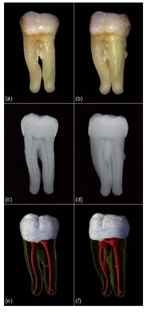
In dental practice, complete visualization of the lateral component of the root canal system is normally not possible. Common radiographic techniques, both conventional and digital, have limited resolution and provide only two-dimensional (2D) projection views. Even though the paralleling technique with orthogonal and eccentric projections improves our understanding, part of the lateral anatomy, especially in the buccolingual (or buccopalatal) plane, will remain invisible (Fig. 11.2a–d). Limited perception of root canal system anatomy may cause procedural difficulties and may invite the clinician to follow a 2D-based approach in a routine-like fashion, where instrumentation to the final working length early in the shaping procedure often causes procedural mishaps.
A new 3D technique for in vitro dental research, called microfocus computed tomography (micro-CT), has provided detailed and accurate visualizations of the external and internal anatomy of teeth, which are useful for scientific and educational purposes (Fig. 11.2e, f) (5). In addition, the ”typical or average anatomy”, as presented for each type of tooth in many textbook tables, has given way to individual appearance being the key to achieving high success of endodontic treatment. Apart from the varying complexity of the lateral component, the anatomy of root canals also differs in terms of curvature, cross-sectional shape, diameter, apical configuration and the extent to which changes have been induced by physiological and pathological processes.
Root canal curvature
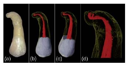
Most root canals are curved instead of straight. In addition, curved root canals are relatively narrow when compared to their straight counterparts. Root canals typically accelerate in curvature and exhibit their greatest anatomical complexity towards their apical terminus (Fig. 11.3). Root canal curvature can be described by level (coronal, middle or apical), angle and radius (29). Most curvatures are multiplanar and are thus expressed in both the mesiodistal and buccolingual (or buccopalatal) plane (Fig. 11.4).
Fig. 11.2 (a, b) Digital photographs of an extracted lower molar. (c, d) Digital radiographic images of the same tooth providing a limited perception of root canal anatomy. (e, f) Micro-CT images showing the system with its lateral components.
The fact that root canals are curved and narrow in mature teeth makes it difficult to clean them of tissue and infectious elements as well as to shape. The risk of canal straightening and the creation of errors are related to the level and severity of the curvature. Abrupt apical curvatures and double curvatures (the S-shape) can be especially difficult to negotiate and shape. In addition, canals that join or diverge always deviate from their initial path. It is important to realize that the resulting angle is often different for the canals involved (Fig. 11.5). Besides complicating the process of instrumentation, root canal curvature results in several other procedural challenges. For example, needle placement and irrigant exchange for the removal of debris are more difficult beyond the curve. Related to visual aids, inspection with the operating microscope is restricted to the straight part of the root canal (above the curve). The creation of straight-line access, the use of flexible endodontic instruments and proper file bending and use are essential measures to prepare curved canals (see further below).
Fig. 11.3 (a) Digital photograph of an upper premolar with a single root that is severely curved towards its terminus. (b, c) Micro-CT images showing the internal anatomy of the root. (d) A detailed view on the anatomical complexity of the apical part.
Cross-sectional shape and diameter
Root canals are round, oval or irregular (ribbon-shaped) on cross-sectional view. Oval and irregular shapes are common in the coronal two-thirds of root canals, whereas the round variant is often restricted to the apical part (Fig. 11.6). Oval cross-sectional shapes are often found in the distal root canals of mandibular molar teeth and in mandibular premolar and incisor teeth. In an investigation of 180 teeth representing all tooth types, Wu and co-workers (46) detected oval root canal shapes in 25% of the specimens investigated. When two or more canals are present in the same root, anastomoses and fins (lateral extensions) are frequently observed (Fig. 11.7). Some root canals may present with extreme cross-sectional shapes. This applies especially to the C-shaped canal (Fig. 11.8), which is more prevalent in certain ethnic groups (16). Oval and irregular cross-sectional shapes certainly do challenge root canal cleaning and shaping. Parts of the lateral anatomy are often out of reach because most end-odontic instruments are designed to stay centered.
Root canal diameter is related to the concept of conicity or “taper”. When looking at the root canal diameter at consecutive levels along the root, an idea of the overall conical shape is obtained. The exact value for diameter and taper will, however, vary for each point along the central axis. Usually root canals are wide in the coronal part and relatively narrow apically. Immature teeth and roots that are liable to some type of resorption may appear different. Also, deposition of reparative dentin may alter root canal diameter generally or locally (i.e. at sites of prior pulpal irritation).
Fig. 11.4 Micro-CT data of a lower first molar. (a–c) Renderings of the outer surface of the roots. (d–f) Visualizations of the root canal system in relation to the outer root surface. Notice that most curvatures are multiplanar, thus expressed in both the mesiodistal and buccolingual plane.
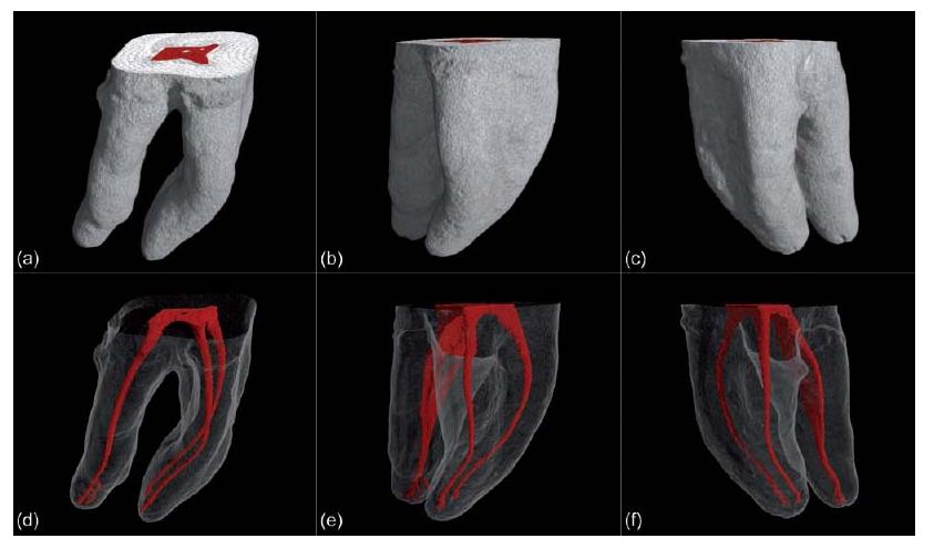
Fig. 11.5 Micro-CT data of an upper premolar. (a, b) Renderings of the outer root surface with a mesial invagination. (c, d) Visualizations of the inner root anatomy. Notice that the root canals that join or diverge deviate from their initial path, while the resulting angle is different for the canals involved.
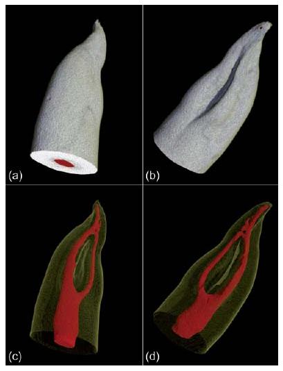
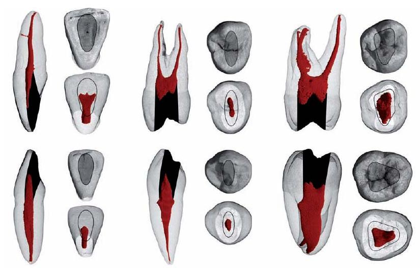
Fig. 11.6 (a, b) Visualizations of a lower premolar scanned with micro-CT. (c–e) Corresponding slices at different horizontal levels (indicated by the yellow lines) reveal the ribbon (c), oval (d), and round (e) cross-sectional shape of the canal.
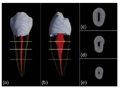
Fig. 11.7 Micro-CT data of a lower first molar. (a, b) Renderings of the outer surface of the roots. (c, d) Corresponding visualizations of the root canal system anatomy. Anastomoses and fins (lateral extensions) are present in both roots.
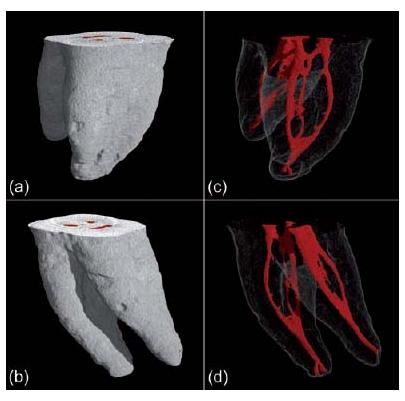
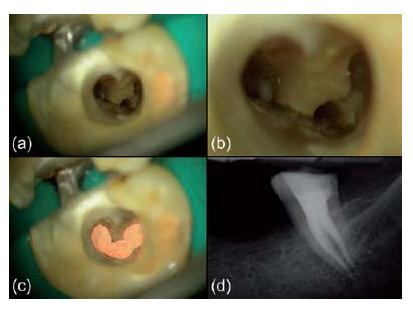
Fig. 11.8 (a–d) Clinical case of a C-shaped canal configuration. (Courtesy of Dr J. Berghmans.)
Apical configuration
In their apical one-third, root canals are often narrow and more or less curved. Their “portals of exit” can have the typical appearance of a foramen apicale (with or without accessory canals) (Fig. 11.9) or the sporadic appearance of an apical delta. Classical work carried out by Kuttler (21) demonstrated that, on average, the narrowest point of the canal (i.e. the apical constriction) is situated 0.48 mm (young group) and 0.60 mm (older group) from the root tip (radiographic apex). Yet there is great variation (9) (Key literature 11.1). The distance from the apical constriction to the foramen apicale is approximately 0.5 mm in the younger group and 0.8 mm in the older group for all tooth types (9, 21). In elderly patients, large amounts of secondary cementum formation may have caused the foramen apicale to move coronally, at a distance of up to 3 mm from the root tip (21). Because of this complex anatomy, the apical one-third of the root canal is prone to procedural errors such as ledges, zips and perforations, making infection control and apical seal difficult.
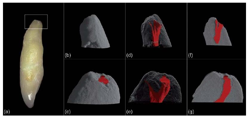
Fig. 11.9 (a) Digital photograph of an upper lateral incisor of which the most apical part (indicated with a white frame) was scanned with micro-CT at very high resolution (pixel size of 1.74 μm × 1.74 μm). (b, c) Renderings of the outer root surface. (d, e) Visualizations of the complex apical anatomy. (f, g) 3D renderings with cut-out to reveal the apical constriction and foramen apicale.
Physiologically and pathologically induced changes
Throughout the life of a tooth with a vital pulp, obliteration and narrowing of parts of the root canal system can occur owing to physiological aging and reparative processes. Low-grade irritation, such as slowly advancing dental caries, root surface exposure due to periodontal disease and acute or chronic trauma (e.g. accidents involving teeth, cavity and crown-related restorative procedures, traumatic occlusion and bruxism) may evoke such pulpal responses. In teeth with a loaded history (e.g. in elderly individuals) the deposition of reparative dentin can be particularly substantial.
The mineralization process usually begins in the coronal part of the root canal system and proceeds apically. Thus, there may eventually be generalized accumulations of hard tissue on the wall of the root canal, narrowing the lumen to such an extent that the canal appears obliterated (Fig. 11.10). Mineralizations may also take the form of pulp stones that are free within the root canal system or attached to the root canal wall. In the pulp chamber of molars the hard tissue tends to form on the roof to shorten the chamber size in a vertical dimension making it difficult to localize root canal orifices upon access preparation. Besides hampering exploration of root canals, canal negotiation is a real challenge in these cases and the creation of a ledge, and subsequent root perforation constitutes a distinct risk.
Procedural steps
Preassessment
After clinical examination and diagnosis, preassessment of the case is imperative, including the construction of a mental image of the tooth to be treated. The preoperative radiographs are carefully examined and the external root surface is palpated or probed. Special attention is paid to:
- a possible inclination of the tooth;
- the cervical contour of the (residual) tooth crown;
- the size of the pulp chamber;
- the amount of obliteration and narrowing of the root canal system;
- the integrity and course of the periodontal ligament;
- the number of roots (and root canals);
- length and diameter of the root(s);
- the degree of root canal curvature (as far as possible).
Field isolation
Asepsis is a strict requirement for non-surgical endodontic treatment. Bacterial contamination of the operation field (the tooth crown and root canal system) is avoided by using rubber dam isolation and disinfection techniques, sterilized instruments and decontaminated materials (see Chapter 4). Every experienced clinician will confirm the view that the use of rubber dam facilitates rather than complicates endodontic treatment. Well-informed patients will accept the use of rubber dam and will appreciate the effort for quality and comfort.
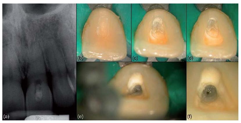
Fig. 11.10 (a) Clinical case of an upper central incisor showing an apparently calcified root canal system. (b–f) Gradual exploration in apical direction towards the deeply situated canal lumen. (Courtesy of Dr J. Berghmans.)
Access opening
Proper access is the key to successful cleaning and shaping of root canals. While the entire roof of the pulp chamber often has to be removed, the outline of the access cavity is dictated by the number and position of the root canal orifice(s) (Fig. 11.11 and Table 11.1).
Initial penetration into the pulp chamber should be undertaken using a bur in a water-cooled high-speed handpiece. Normally a safe direction to avoid misalignment and excessive damage to the crown is towards the widest root canal (e.g. palatal root in upper molars and distal root in lower molars). Once into the pulp chamber, overhanging margins must be removed. One may then shift preparation technique to a slow-speed handpiece without water coolant in order to enhance visualization. Useful burs in this phase of the access preparation are long-shanked round burs. In cases where localization of the pulp chamber appears challenging, rubber dam placement may be delayed until an opening has been found. The advantage of this measure is to get indications on root inclinations and furcation grooves by probing the external root surface. Root surface probing can be especially useful in cases of premolars with multiple canals in the buccal root, and in cases of preparation through a metal crown.
Complete removal of the existing coronal restoration is advised in most cases because it:
- allows better radiographic interpretation of the anatomy of the coronal part of the root canal system;
- allows complete inspection of the residual crown (e.g. for the detection of possible fractures);
- solves marginal leakage;
- detects hidden caries;
- provides a better view of the pulp chamber in the presence of more refracted light;
- prevents inconsistent readings when using electronic apex locators;
- prevents metal filings from entering the canal.
Once uncovered, the floor of the pulp chamber can be examined like a map in order to explore the root canal system anatomy. Care should be taken to avoid damaging the floor of the pulp chamber as the root canal orifices are to be sought along the groove system. A straight sharp-tipped explorer is handy here. In cases of gross depositions of mineralized tissue, exploration of the connecting grooves can be done using ultrasonically powered instruments (used at low power settings and with a light touch) or with long-shanked round burs in a slow-speed (800-1000 rpm) handpiece. Slight differences in color between the walls of the pulp chamber and the floor assist in finding the root canal entrances (Fig. 11.12).
Fig. 11.11 Images of the upper (top) and lower (bottom) dentition generated with micro-CT. The outline of the access cavity (i.e. the black area that was added to the image) is dictated by the position of the root canal orifice(s), while the entire roof of the pulp chamber has to be removed.
Cavity walls are adjusted to reflect the operating light and to allow straight-line entry to the root canal(s). For example, in order to locate the MB2 (second canal in the mesiobuccal root) in maxillary molars, the access cavity should be created with a clear extension towards the mesial side (Fig. 11.13). All cavity walls are then smoothed and connected with the orifice(s) of the respective canal(s). The latter simplifies re-entry into the canal, especially when irrigants are present, without buckling the tip of small files. Of course, access cavity preparation should be performed after careful examination of the undistorted preoperative radiograph(s) and with respect for the integrity of the crown.
Initial root canal preparation (coronal preflaring)
As a general rule, the removal of root dentin should be centered, i.e. with respect to the initial root canal anatomy. In the coronal one-third of a curved root canal, however, this concept is intentionally ignored. Indeed, by carefully relocating the root canal orifice (using for instance Gates–Glidden burs), the degree of mid-root curvature is decreased without weakening the tooth (Fig. 11.14). The creation of a “straight-line access” is mandatory to avoid obstruction of the intracanal view, root canal straightening and instrument separation.
Regarding the adopted technique for instrumentation, one makes a distinction between file movement and shaping approach. The latter is related to the instrument sequence and file insertion depth. In general, a coronal-to-apical approach is advised because:
- coronal preflaring allows more control during subsequent preparation of the middle and apical one-thirds;
- the risk of canal blockage, ledge formation and instrument fracture is reduced;
- working length determination is more precise after coronal preflaring.
In the modified double flared approach, for instance, the coronal portion of the root canal is flared first (from orifice to curvature) (see Clinical procedure 11.1). In cases of curved and narrow canals, the root canal is gradually explored and flared first, and care is taken not to overload any specific instrument as it may create a ledge. An error that is commonly made during this initial procedure is to overuse files, especially the smaller sizes. Instead of wasting one file after the other, sizes 06-10 K-files should be used in combination with flexible K-files sizes 15–30 to cut more coronal shape in big increments (i.e. the “serial step-back negotiation”). The smaller-sized K-file, which was resisting further advancement, may then advance deeper into the root canal because the shank portions are released from binding. In all situations, the act of recapitulation represents a safe and effective strategy for root canal negotiation.
Table 11.1 Root canals in teeth of maxilla and mandible.
| Maxilla | |
| Central incisor | 1 canal 100% |
| Lateral incisor | 1 canal 100% |
| Canine | 1 canal 100% |
| 1st premolar | 2 roots 57% |
| Single root, 2 canals 16% | |
| Single root, 2 canals, 1 foramen 12% | |
| 3 roots, 3 canals 6% | |
| 2nd premolar | 1 canal 53% |
| 2 canals, 1 foramen 22% | |
| 2 canals, 1 foramen 13% | |
| 2 roots, 2 canals 11% | |
| 3 roots, 3 canals 1% | |
| 1st molar | 3 roots, 3 canals 38% |
| 4 canals 60% | |
| Mesiobuccal canal: 2 canals 60% | |
| 2 foramina 20% | |
| 1 foramen 80% | |
| 2nd molar | 3 roots 60% |
| 1 mesiobuccal canal 70% | |
| 2 mesiobuccal canals: 1 foramen 15% | |
| 2 foramina 10% | |
| 2 roots 25% | |
| 1 root 10% | |
| Mandible | |
| Central incisor | 1 canal 70% |
| Lateral incisor | 1 canal 55% |
| 2 canals, 2 foramina: central 5% | |
| lateral 15% | |
| 2 canals, 1 foramen: central 25% | |
| lateral 30% | |
| Canine | 1 canal 70% |
| 2 canals, 1 foramen 20% | |
| 2 canals, 2 foramina 10% | |
| 1st premolar | 1 canal, 1 foramen 74% |
| Branching canal: 1 foramen 4% | |
| 2 foramina 25% | |
| 2nd premolar 1 canal, 1 foramen 97% | |
| Branching canal: 1 foramen 12% | |
| 2 foramina 3% | |
| 1st molar | 2 mesial canals 60%, 1 foramen 40% |
| 1 distal canal 70% | |
| Distal canal: 2 canals, 1 foramen 35% | |
| 2 canals, 2 foramina 10% | |
| 2nd molar | 2 mesial canals 40%, 1 foramen 35% |
| 1 canal 25% | |
| 1 distal canal 92% | |
| 2 canals, 1 foramen 5% | |
| 2 canals, 2 foramina 3% | |
| Can have a C-shaped distal canal |
Fig. 11.12 (a, b) Clinical case of an upper first molar. (c–f) Creation of access and exploration of three canal orifices within the mesio-buccal root. (g–j) Root canal preparation, filling and radiographic control. (Courtesy of Dr J. Berghmans.)
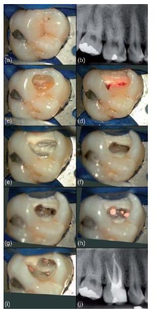
Fig. 11.13 (a) Access cavity in a maxillary molar with a clear extension towards the mesial side. (b–d) Root canal negotiation and preparation. (Courtesy of Dr J. Berghmans.)
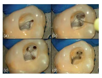
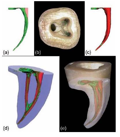
Fig. 11.14 Micro-CT data showing the mesial root canals of a lower molar (a) before (green) and (c) after (red) instrumentation with ProTaper. (b) Micro-CT generated contours layered on a digital photograph of the pulp chamber floor. Straight-line access is created by relocating the root canal orifices (i.e. from the green to the red contour line). (d, e) 3D renderings of the outer root surface and internal anatomy after registration of both datasets. (Preparation by Dr C. Ruddle.)
Stay updated, free dental videos. Join our Telegram channel
VIDEdental - Online dental courses


