Introduction
The purpose of this study was to compare the pattern and amount of stress and displacement between maxillary protraction with miniplates placed at the infrazygomatic crest and the lateral nasal wall.
Methods
Three-dimensional finite element models for the skull and the curvilinear type of miniplate were constructed. After a protraction force (500 g/side) was applied to the distal end of the miniplate with a forward and 30° downward vector to the maxillary occlusal plane, stress distributions in the circummaxillary sutures and displacements of the surface landmarks were analyzed.
Results
There was a difference in the maximum stress distribution area according to the site of the miniplate: infrazygomatic crest and middle part of the maxilla in the infrazygomatic crest and paranasal area adjacent to the pyriform aperture in the lateral nasal wall. Stress values of the frontonasal, frontomaxillary, zygomaticomaxillary, and pterygomaxillary sutures were greater in the infrazygomatic crest than in the lateral nasal wall. The site of the miniplate produced differences in the major displacement areas: infrazygomatic crest, maxillary dentition, anterior maxilla, and upper part of the maxillary tuberosity in the infrazygomatic crest and the lateral nasal wall, maxillary dentition, anterior maxilla, and lower part of the maxillary tuberosity in the lateral nasal wall. The lateral nasal wall exhibited forward, downward, and outward displacements of ANS, Point A, and prosthion. However, the infrazygomatic crest showed forward and upward displacements of ANS, Point A, and prosthion, and outward displacement of the zygomatic process of the maxilla and the maxillary process of the zygomatic bone.
Conclusions
The site of miniplate placement should be considered to obtain proper stress and displacement values in different areas with maxillary hypoplasia.
Therapy with a facemask has been regarded as an appliance of choice to treat growing Class III patients with mild to moderate maxillary hypoplasia. Although facemask therapy can induce advancement of the maxilla and the circummaxillary complex depending on the force generated at the sutures, more favorable outcomes might be expected in patients in the deciduous or early mixed dentition than in those with late mixed dentition. To transmit the orthopedic force from the facemask to the maxilla, tooth-borne anchorage with a labiolingual arch, a quad-helix appliance, and rapid maxillary expansion have been used. However, usage of the maxillary dentition as anchorage cannot avoid unwanted side effects such as labioversion of the maxillary incisors, extrusion of the maxillary molars, counterclockwise rotation of the palatal plane, and eventual clockwise rotation of the mandible.
To allow the direct transmission of orthopedic force to the circummaxillary sutures, intentionally ankylosed deciduous canines, osseointegrated onplants and implants, and orthodontic miniscrews have been used as skeletal anchorage for maxillary protraction. Since a surgical miniplate can be regarded as a reliable anchorage tool for applying the orthopedic forces to the maxillofacial skeletal complex, facemask therapy with miniplate anchorage placed at the infrazygomatic area or the lateral nasal wall of the maxilla has been introduced to treat patients with Class III malocclusion with maxillary hypoplasia or hypodontia.
Three-dimensional (3D) finite element model analysis can enumerate the biomechanical variables such as stress, strain, and displacement in the maxillofacial complex induced by various conditions of force and direction in maxillary protraction. Several studies have evaluated the biomechanical changes of the maxillofacial structures with facemask therapy combined with tooth-borne anchorage. However, few biomechanical studies have been undertaken about the effects of facemask therapy with miniplate anchorage on the maxillofacial structures in the infrazygomatic area and the lateral nasal wall. Since these models have different positions of the miniplates in the maxillofacial skeletal structure, there can be differences in stress distribution in the circummaxillary sutures and in displacement of the surface landmarks in the maxillofacial bones.
Therefore, the purpose of this study was to compare stress distribution in the circummaxillary sutures and displacement of the surface landmarks in the maxillofacial bones between the infrazygomatic area and the lateral nasal wall models by using 3D finite element model analysis. The null hypothesis was that there are no differences in the pattern and amount of sutural stress and landmark displacement according to the position of the miniplates.
Material and methods
Computed tomography scans (SCT-6800TXL; Shimadzu, Tokyo, Japan) (120 kVp, 230 mA, 1:1.2 pitch, scanning time of 1.5 seconds, 3-mm intervals in the axial direction, parallel to the Frankfort horizontal plane) of the skull of a girl (age, 13.5 years) who had a retrusive maxilla and an anterior crossbite were taken to obtain the horizontal images from the maxillary occlusal plane to the superior margin of the cranium. A surface 3D model of the skull was reconstructed from the computed tomography images by using a 3D imaging process software package (Mimics 7.10; Materialise, Leuven, Belgium). This geometric model (STL format) was edited and meshed into a 3D finite element model by using Simulation software (version 2011; SolidWorks, Concord, Mass).
Six craniofacial sutural systems were integrated into the model. After the nodes corresponding to the anatomic sutures (frontonasal, frontomaxillary, zygomaticomaxillary, zygomaticotemporal, zygomaticofrontal, and pterygomaxillary) were identified, pairs of nodes were created along the entire suture length. The thickness of each suture was modeled with an even thickness of 0.5 mm. This modeling can allow stress displacement in the sutural system and independent displacement of the surface landmarks at the bony structures in response to simulated orthopedic forces.
Also, a 3D finite element model for a curvilinear type of surgical miniplate with 6 holes (thickness, 0.80 mm; length, 31.65 mm; hole diameter, 2 mm; distance between the centers of the holes, 5.50 mm; curvature, 0.04 mm −1 ; LeForte system, Jeil Medical, Seoul, Korea) was designed based on 3D computer-aided design data and fixed according to the anatomic shape of the infrazygomatic crest and the lateral nasal wall of the maxilla by the projection method. In the lateral nasal wall model, the distal end of the miniplate was placed 2 mm above the gingival crest of the alveolar bone between the maxillary lateral incisor and the canine, and the mesial end of the miniplate was located 3 mm from the pyriform aperture. In the the infrazygomatic area model, the distal end of the miniplate was placed 2 mm above the gingival crest of the alveolar bone between the maxillary canine and first premolar, and the mesial end of miniplate was located 5 mm anterior to the infrazygomatic crest. The part of the miniplate around the upper 3 holes was simulated to be rigidly bonded to the bony surface area as if 2-mm diameter miniscrews were inserted through the upper 3 holes.
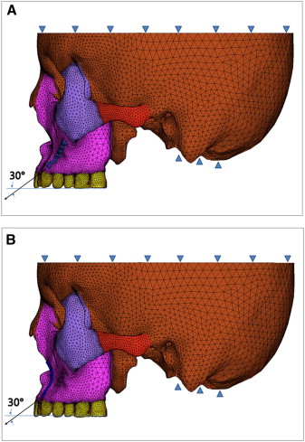
The 3D finite element model in this study consisted of 317,572 first tetrahedral elements, 64,772 nodes, and 194,316 degrees of freedom ( Fig 1 ). The mechanical properties of cortical and cancellous bones, teeth, sutures, miniplate, and miniscrews in the 3D finite element model are shown in Table I .
| Material | Young’s modulus (MPa) | Poisson’s ratio |
|---|---|---|
| Cortical bone | 1.37 × 10 4 | 0.30 |
| Cancellous bone | 7.9 × 10 3 | 0.30 |
| Miniplate | 1.05 × 10 5 | 0.33 |
| Miniscrew | 1.05 × 10 5 | 0.33 |
| Suture | 7 | 0.40 |
| Tooth | 2.07 × 10 4 | 0.30 |
Restraints were established at all other nodes of the cranium lying on the symmetrical plane. In addition, a zero-displacement boundary condition was imposed on the nodes along the foramen magnum ( Fig 1 ).
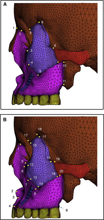
Protraction forces (500 g/side) were applied to the distal ends of the miniplates of both models with a 30° downward and forward vector to the maxillary occlusal plane, respectively ( Fig 1 ). Stress distribution in the circummaxillary sutures and displacement of the surface landmarks in the maxillofacial bone were analyzed by using ANSYS software (version 12.1; Belcan Engineering, Cincinnati, Ohio). The locations of the suture points and the surface landmarks in the maxillofacial bone are shown in Figure 2 .
Results
Although both models did not show stress concentration in the maxillary dentition, there was a difference in the patterns of stress distribution between the infrazygomatic area and the lateral nasal wall models. The stress was concentrated mainly on the infrazygomatic crest and the middle part of the maxilla in the infrazygomatic area model ( Fig 3 , A ) and on the roots of the maxillary canines and first premolars and the paranasal area adjacent to the pyriform aperture in the lateral nasal wall model ( Fig 3 , B ).
Both models showed the maximum von Mises stresses at the pterygomaxillary, zygomaticotemporal, zygomaticomaxillary, and frontonasal sutures in descending order ( Table II ). However, the stress values of the frontonasal, the frontomaxillary, the zygomaticomaxillary (superior and middle portions), and the pterygomaxillary sutures were higher in the infrazygomatic area model than in the lateral nasal wall model ( Table II ).
| Suture | MP-IZ (MPa) | MP-LN (MPa) |
|---|---|---|
| Frontonasal | 2.09E-03 | 1.86E-03 |
| Frontomaxillary | 1.20E-03 | 9.61E-04 |
| Zygomaticomaxillary | ||
| Superior | 5.98E-04 | 4.57E-04 |
| Middle | 2.12E-03 | 1.01E-03 |
| Inferior | 1.79E-03 | 1.89E-03 |
| Zygomaticotemporal | ||
| Superior | 5.90E-04 | 5.84E-04 |
| Inferior | 2.82E-03 | 2.68E-03 |
| Zygomaticofrontal | ||
| Posterior | 2.55E-04 | 3.17E-04 |
| Anterior | 2.35E-04 | 2.63E-04 |
| Pterygomaxillary | ||
| Superior | 4.83E-03 | 3.69E-03 |
| Inferior | 4.44E-03 | 3.28E-03 |
Similar to the stress distribution, the positions of the miniplates affected the pattern of displacement. The infrazygomatic area model showed greater displacements of the infrazygomatic crest area, the maxillary dentition, the anterior maxilla, and the upper part of the maxillary tuberosity ( Fig 4 , A ), whereas the lateral nasal wall model exhibited the main displacements on the lateral nasal wall area, the maxillary dentition, the anterior maxilla, and the lower part of the maxillary tuberosity ( Fig 4 , B ).
In the sagittal plane, maximum forward displacements were observed at the anterior nasal spine (ANS), Point A, prosthion, and posterior nasal spine (PNS) in the maxilla in both models ( Table III ). These values showed an increasing tendency in the infrazygomatic area model and a decreasing tendency in the lateral nasal wall model from ANS and Point A to prosthion ( Table III ). However, forward displacement values of the surface landmarks in the inferior orbital rim and zygomatic process of the maxilla, the zygomatic bone, the frontal bone, and the temporal bone were almost same ( Table III ).
| Region | Surface landmarks | MP-IZ | MP-LN | ||||
|---|---|---|---|---|---|---|---|
| X (mm) | Y (mm) | Z (mm) | X (mm) | Y (mm) | Z (mm) | ||
| Maxilla | Frontal process | −7.24E-08 | 9.72E-06 | 2.23E-04 | −9.65E-08 | 7.89E-06 | 2.23E-04 |
| ANS | −3.44E-07 | 7.17E-05 | 3.77E-04 | 3.05E-05 | −6.90E-05 | 4.31E-04 | |
| Point A | −7.64E-06 | 6.56E-05 | 4.06E-04 | 3.53E-05 | −7.24E-05 | 4.27E-04 | |
| Prosthion | −2.08E-05 | 7.87E-05 | 4.32E-04 | 2.68E-05 | −8.02E-05 | 4.11E-04 | |
| Inferior orbital rim | 1.68E-05 | 2.07E-05 | 2.70E-04 | 1.57E-05 | 1.47E-05 | 2.64E-04 | |
| Zygomatic process, superior | 1.80E-05 | 2.12E-05 | 2.70E-04 | 1.64E-05 | 1.37E-05 | 2.64E-04 | |
| Zygomatic process, middle | 2.56E-05 | 2.30E-05 | 3.13E-04 | 2.12E-05 | 1.31E-05 | 3.04E-04 | |
| Zygomatic process, inferior | 2.43E-05 | −1.98E-06 | 3.33E-04 | 1.82E-05 | −1.01E-05 | 3.25E-04 | |
| PNS | 1.61E-05 | −7.39E-06 | 3.90E-04 | 2.52E-7 | −7.28E-05 | 4.16E-04 | |
| Zygomatic bone | Frontal process, anterior | 3.02E-06 | 1.84E-06 | 2.14E-04 | 1.17E-06 | 3.51E-08 | 2.14E-04 |
| Frontal process, posterior | −6.27E-06 | −7.98E-06 | 2.03E-04 | −6.59E-06 | −9.73E-06 | 2.04E-04 | |
| Maxillary process, superior | 2.60E-05 | 8.15E-06 | 2.70E-04 | 2.06E-05 | 3.45E-06 | 2.65E-04 | |
| Maxillary process, middle | 3.12E-05 | 6.25E-06 | 2.91E-04 | 2.49E-05 | 1.67E-06 | 2.84E-04 | |
| Maxillary process-inferior | 2.61E-05 | −7.12E-06 | 2.99E-04 | 1.99E-05 | −1.05E-05 | 2.91E-04 | |
| Temporal process, superior | −9.10E-06 | −3.20E-05 | 2.29E-04 | −1.07E-05 | −3.24E-05 | 2.29E-04 | |
| Temporal process, inferior | −1.85E-05 | −3.91E-05 | 2.49E-04 | −1.96E-05 | −3.84E-05 | 2.46E-04 | |
| Frontal bone | Zygomatic process, anterior | 1.31E-06 | 3.86E-06 | 2.12E-04 | 2.11E-7 | 2.86E-06 | 2.12E-04 |
| Zygomatic process, posterior | −7.99E-06 | −3.73E-06 | 2.01E-04 | −8.23E-06 | −4.66E-06 | 2.02E-04 | |
| Temporal bone | Zygomatic process, superior | −2.28E-05 | −4.49E-05 | 2.19E-04 | −2.39E-05 | −4.45E-05 | 2.19E-04 |
| Zygomatic process, inferior | −2.26E-06 | −4.03E-05 | 2.11E-04 | −3.55E-06 | −3.97E-05 | 2.10E-04 | |
Stay updated, free dental videos. Join our Telegram channel
VIDEdental - Online dental courses


