Procedures in Endodontics
Francesco Mannocci, Justin Barnes, David Jones, Edward Brady, Malissa Sikun and Manjeet Ahlowalia
Diagnosis
The diagnostic process is made up of three stages: history taking, examination and special tests/investigations. These procedures are fully described in Chapter 6. Only aspects directly pertinent to endodontic diagnosis will be considered here.
Presenting Complaint
Endodontic presenting complaints commonly include pain/discomfort, swelling, discharge, bad taste, and/or tooth discolouration.
History of Presenting Complaint
A pain history (Table 12.1) is essential not only to arrive at a diagnosis but also to determine the urgency for treatment. Pain aggravated by thermal stimuli is an indicator of pulpitis and severe pain is usually an indicator of irreversible pulpitis or periapical abscess.
Table 12.1 Pain history questions.
| Category | Questions |
| Character | ‘Describe the pain for me’ |
| Severity | ‘How severe is the pain on a scale of 1 to 10 with 10 being the worst pain you have every experienced?’ |
| Chronology (onset, frequency, duration) |
‘When did the problem start?’ ‘When does the pain come on?’ ‘Are you kept awake or woken by the pain?’ ‘How long does the pain last?’ ‘How often do you get the pain?’ |
| Site and referral | ‘Where do you feel the pain?’ ‘Can you locate the pain to a specific tooth or just a general area?’ ‘Does the pain radiate anywhere else?’ |
| Aggravating factors | ‘Is there anything which brings on or makes the pain worse?’ ‘Do cold or hot substances make the pain worse?’ |
| Alleviating factors | ‘Is there anything which alleviates the pain?’ ‘Have you taken painkillers or antibiotics for the pain?’ |
Special Tests/Investigations
Special tests/investigations are an aid to diagnosis. The clinician should not rely on one test/investigation to arrive at a diagnosis; several should be performed and collectively analysed.
Palpation of Sulci
Procedure: roll index finger, under pressure, over buccal/labial and lingual/palatal mucosa in the region of the root apices. Instruct patient to signal if they feel an unpleasant sensation. Compare with contralateral side.
Analysis: tenderness to palpation is usually an indicator of inflammation of the periapical tissues.
Percussion of Teeth
Procedure: gently ‘tap’ teeth using a dental mirror handle. Repeat on occlusal, buccal/labial, and lingual/palatal surfaces. Randomly number the teeth and instruct patient to signal if they feel an unpleasant sensation. Comparison with contralateral and to obviously unaffected unilateral teeth is essential
Analysis: tenderness to percussion is usually an indicator of inflammation of the periodontal ligament. This may be endodontic or, less frequently, non‐endodontic in origin (e.g. trauma, parafunction).
Bite Test
The bite test uses a plastic bite stick (e.g. Tooth Slooth) to determine if there is a cracked cusp.
Procedure:
- Place indentation of a plastic bite stick on cusp tip.
- Instruct patient to close their teeth together with pressure and signal if they feel pain on biting or on release of biting.
- Repeat on each cusp tip of tooth.
Analysis: a painful response, usually on release of biting, is an indicator of a cracked tooth.
Pulp Sensibility Tests
Sensibility tests assess the response of pulpal nerves to various stimuli, for example cold, hot and electric. The results of these tests can be used to infer whether the pulp is vital or not.
- The results of sensibility tests are subjective and qualitative. Interpretation of the results should be made carefully as tests are not 100% accurate.
- Care should be taken to identify false results.
- False positive results may occur more often in multirooted teeth where only partial necrosis has occurred, in anxious patients, or due to conduction from adjacent teeth.
- False negative results may occur in immature teeth, calcified coronal pulp chambers, traumatised teeth, or in teeth with large coronal restorations.
Cold Sensibility Test
Cold tests can be performed using a variety of materials:
- Ice.
- Ice cold water while the tooth is isolated under a rubber dam.
- Ice crystals formed on foam pellets or cotton wool pledgets using ethyl chloride or refrigerant sprays (e.g. Endo‐Frost, Figure 12.1).
- Dry ice sticks (CO2 snow).
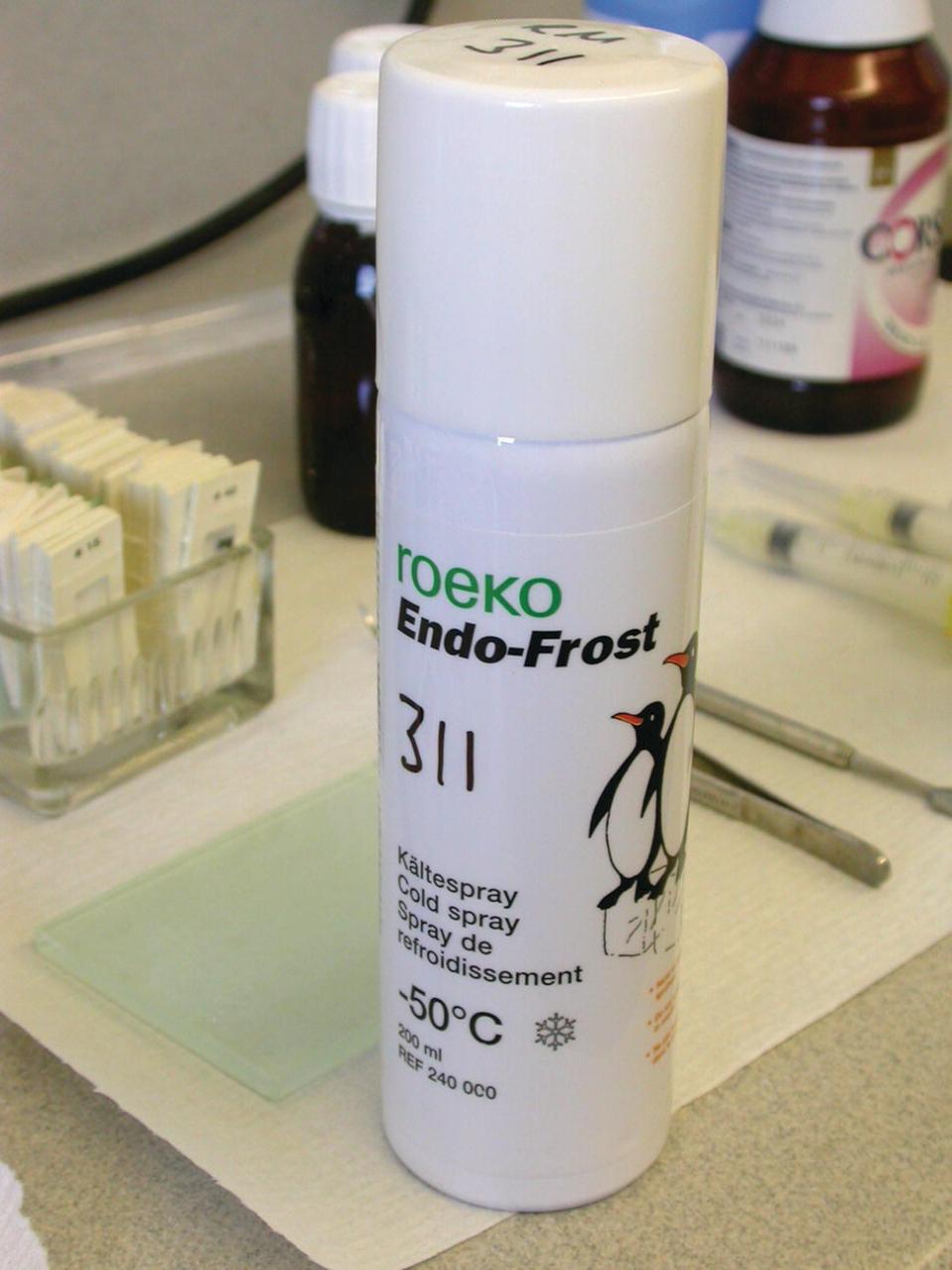
Figure 12.1 Refrigerant spray for cold sensibility testing.
It is generally accepted that the colder the stimulus, the more reliable the test.
Procedure:
- Dry teeth.
- Instruct patient to indicate when they feel a sensation. Apply cold stimulus to tooth surfaces.
- Compare with the contralateral tooth and adjacent teeth.
- Repeated testing may be required to ensure reproducibility of results.
Analysis: it is generally accepted that a fleeting sharp sensation is an indicator of a healthy pulp, and a lingering ache or throbbing is an indicator of an irreversibly inflamed pulp. No response may be an indicator of a necrotic pulp.
Heat Sensibility Test
Heat tests are only performed when the patient is complaining of pain aggravated by a hot substance and the diagnosis is not easily achieved by using a cold sensibility test. Heat tests can be performed using a variety of materials and equipment:
- Heated gutta percha point (tooth should be coated with petroleum jelly).
- Warm water while the tooth is isolated under a rubber dam.
- Heated probe (e.g. Elements obturation unit).
- A prophy cup to create frictional heat.
Procedure: similar to cold testing.
Analysis: similar to cold testing.
Electric Sensibility Test
Electric tests are performed using a battery‐operated electric pulp tester (Figure 12.2).

Figure 12.2 Electric pulp tester.
Procedure:
- Dry teeth.
- Instruct patient to signal when they feel a ‘tingling sensation’.
- Place a conducting medium (e.g. prophy paste) on the pulp tester probe. Apply probe to tooth surface over where the pulp horns are located.
- Complete circuit with lip hook or patient holding end of probe.
- Slowly increase current on unit until patient gives signal.
- Compare with the contralateral tooth and adjacent teeth.
- Record reading of lowest current, which elicits a response.
Analysis: a response is usually an indicator of a healthy pulp. No response is usually an indicator of a necrotic pulp.
Physiometric Tests
Physiometric tests assess the pulpal blood supply and are therefore true vitality tests, e.g. laser Doppler flowmetry, pulse oximetry. These tests are technique sensitive, take time to assess data and are generally not frequently used in daily clinical practice.
Local Anaesthetic Test
Administration of local anaesthetic can be useful when the patient is unable to localise pain to a specific tooth or region.
Procedure: local anaesthetic is administered as an infiltration or intraligamental.
Analysis: if selective local anaesthesia of the suspected tooth stops the pain, then this is the source of the pain. If the local anaesthesia does not stop the pain, then the clinician may need to look at other areas for the source of the pain. This may include considering non‐odontogenic causes of pain.
Test Cavity Preparation
A test cavity should only be performed when all other special tests are inconclusive.
Procedure: as with any invasive procedure, explain the nature of the test and obtain consent from the patient. Under rubber dam and without local anaesthesia, drill a small cavity through enamel (or restoration) into dentine using a diamond bur in a high‐speed handpiece. Restore cavity.
Analysis: a response is an indicator of a vital pulp, which may or may not be inflamed. No response is usually an indicator of a necrotic pulp.
Removal of Restoration
It is useful to remove the entire coronal restoration to assess restorability of the tooth and identify any underlying tooth fractures or caries. The exception to this may be a recently provided well‐fitting cast restoration.
Photography
It is now routine to take high quality photographs to record the preoperative status.
Radiographic Examination
Periapical radiographs provide useful information to aid endodontic diagnosis.
- Sometimes a parallax view provides additional valuable information.
- If a sinus is present, then a radiograph should be taken with a gutta percha point inserted in the sinus so that the origin of the infection can be more easily identified.
Procedure:
- Use a paralleling technique.
- Place the film, phosphor plate or charged‐couple device sensor in a holder and position parallel to the long axis of the tooth.
- Position the collimated X‐ray tube head using an aiming device.
- View film‐based radiographs in optimal conditions, i.e. on a light box, blocking out extraneous light. View digital radiographs on a computer screen using imaging software.
Analysis:
- Widening of the periodontal ligament space, a breach in the lamina dura, or a periapical radiolucency in the surrounding bone are all indicators of apical periodontitis.
- Asymmetrical loss of the root and ‘ballooning’ of the root canal are indicators of root resorption. For treatment planning, it is also important to assess the number of roots, degree of curvature of roots, and the quality of any existing root filling and coronal restoration.
The clinician should remember the limitations of conventional radiographs, i.e. two‐dimensional representation with superimposition of structures. Cone beam computed tomography (CBCT) may be indicated:
- To obtain a more accurate assessment of the extent of external resorptions.
- To obtain an assessment of the risk of perforations associated with internal resorptions or complex anatomy.
- When the presence of a periapical radiolucency is difficult to ascertain due to the superimposition with adjacent anatomical structures such as the maxillary sinus, or due to the presence of thick cortical bone plate surrounding the lesion (Figure 12.3).
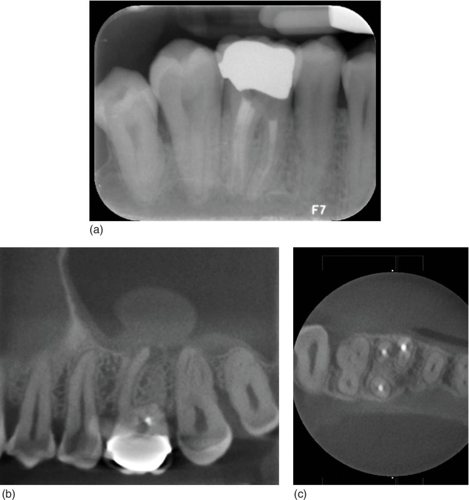
Figure 12.3 (a) Root canal treated maxillary first molar showing apparently healthy periapical tissues. (b) Apical radiolucency associated with the mesial root and with a significant thickening of the antral mucosa. (c) The mesiobuccal root shows an untreated mesiopalatal canal.
Conclusion
Endodontic diagnosis is always an educated guess based upon a complex array of tests; it is only after the collection of all the information that a reliable diagnosis can be reached.
Preparation for Endodontic Treatment
Preparation of the patient includes:
- An explanation of the procedure and expected length of treatment.
- A discussion regarding the likelihood of success/outcome.
- Discussion of alternatives to root canal treatment and discussion of their implications (extraction, implant, do nothing).
- Advising the patient if a crown will be necessary following completion of treatment.
- An understanding on the part of the patient that the tooth may prove to be unrestorable if something untoward is discovered (e.g. a crack).
This comprises informed consent.
Preparation of the tooth for endodontic treatment can be thought of as falling into two distinct parts:
- Procedures to facilitate endodontic treatment.
- Isolation with a rubber dam.
Procedures to Facilitate Endodontic Treatment
Prior to commencing access cavity preparation:
- All caries must be removed from the tooth.
- It is also normal practice to remove all restorations from the tooth. This enables a thorough assessment of the quantity and integrity of the remaining tooth structure to be performed.
In cases where there is adequate sound dentine and enamel, then access cavity preparation can be commenced. In other cases a variety of procedures may be necessary to further prepare the tooth for endodontic treatment.
Such procedures may include:
- Using restorative materials to build up a tooth to facilitate isolation.
- Cementation of a copper or orthodontic band.
- Surgical crown lengthening.
- Orthodontic extrusion.
On some occasions it may be necessary to use a composite or glass ionomer to build up one or two walls of a tooth. This may be necessary to prevent leakage of saliva and irrigant around a cavity margin or simply to create a reservoir for the irrigant during endodontic treatment.
In cases where there is concern regarding the propagation of cracks or fracture of a weak tooth during endodontic treatment, the cementation of a copper band or orthodontic band may be beneficial. Orthodontic bands are suitable for use when the cavity margins are supragingival and a suitably sized band can be quickly cemented with zinc phosphate or glass ionomer cement. Once the cement has set, a rubber dam can be applied and the tooth accessed as normal.
Copper bands are more useful when the cavity margins are subgingival, or the cavity margins vary in depth. Copper bands are favoured in this situation because they can be trimmed and burnished to accommodate such discrepancies. The contact points are removed from the tooth to be treated using abrasive strips and the occlusal surface reduced. A suitably sized band is selected and trimmed appropriately before being cemented and burnished. Placing bands on teeth in this manner facilitates the isolation, endodontic treatment and restoration of teeth with subgingival cavity margins, as well as reinforcing vulnerable teeth during treatment.
It is desirable for such bands to be removed as soon as possible after treatment, but it is acceptable to leave them in situ until it is time to prepare the tooth for a crown, provided the patient can maintain adequate oral hygiene.
After removing any caries and all intracoronal restorations, if there is insufficient coronal tissue remaining for restoration or there is not enough to create a ferrule, the restorability of the tooth must be questioned.
- In some circumstances it may be possible to perform surgical crown lengthening to increase the amount of coronal tissue available.
- Following the surgery, in particular for posterior teeth, well‐fitting temporary crowns should be provided for a 2–3 month healing phase before the construction of the definitive restoration.
- Another option in this situation is rapid orthodontic extrusion of the tooth, although an orthodontic opinion would need to be sought to confirm suitability for this procedure.
In some situations, the clinician may choose not to remove all restorations from the tooth prior to embarking on endodontic treatment. Such occasions may include:
- Recently cemented crowns.
- Recently placed large fillings.
- Veneers.
In these situations, the patient must be made aware that there is the potential for damage to these restorations, necessitating replacement, with the associated costs.
Undertaking a root canal treatment through crowns or existing fillings is generally contraindicated due to the risk of leaving undetected decay and paths of coronal leakage of bacteria into the root canal space. If attempting to perform endodontic treatment through a crown, the clinician must be aware that the restoration will prevent transmission of light into the tooth and so will reduce visualisation of the internal anatomy, making the procedure more time consuming. In these situations, the operating microscope, which provides magnification and axial light, is invaluable
Rubber Dam
When one considers the biological aim of endodontic treatment (i.e. to eradicate all bacteria from the root canal system) it is obvious that the prevention of contamination of the surgical site by saliva and other fluids is essential for a favourable outcome. The simplest and most effective means of achieving this is by using a rubber dam.
A rubber dam is easy and, with practice, quick to place. Its use will facilitate:
- Prevention of bacterial contamination.
- Soft tissue retraction.
- Improved visualisation of the surgical site.
- Prevention of irrigant leakage into the patient’s mouth.
- Protection against inhaling/ingesting instruments.
The importance of a rubber dam in endodontics simply cannot be overstated. Most defence organisations consider its use mandatory and will not defend a dentist who has not used a rubber dam during endodontics.
The use of a rubber dam will make the procedure easier to tolerate for the patients because they perceive it to be less invasive. Soft tissues such as the lips and tongue are retracted improving access for the dentist, making the procedure less stressful and much easier and faster. The colour contrast between the surgical site and the rubber sheet improves visualisation of the tooth.
Rubber dam apparatus usually consists of a clamp, frame, forceps, punch and a rubber sheet. The rubber sheet comes in a variety of thicknesses and styles, and may be made of latex or be latex‐free. A hole‐punch is required to create a clean hole near the centre of the sheet for the tooth which is being isolated. Most punches allow for a variety of sizes of holes to be created, and the size most appropriate for the tooth must be selected to create a snug fit (Figure 12.4).

Figure 12.4 Rubber dam kit.
Rubber dam clamps come in a variety of shapes and sizes and vary between manufacturers. In general, they are classified as winged or wingless. Winged clamps are designed so that the clamp and the rubber dam are placed onto the tooth in one application. Wingless clamps are placed directly onto the tooth and then the rubber dam is passed over the clamp and onto the tooth. The forceps are used for the application of the clamp in both these techniques.
Clamps can also be defined based upon the jaws used to engage the neck of the tooth. ‘Retentive’ clamps have quite sharp, pointed jaws that are orientated apically which grip the tooth firmly and reflect the gingival tissues. These clamps are useful in broken‐down teeth, or teeth with insufficient undercuts to retain a ‘bland’ clamp. The jaws of ‘bland’ clamps are orientated towards each other and are designed to simply engage the natural undercut of the tooth. ‘Tiger’ clamps have serrated jaws, which are very effective for gripping molar teeth firmly.
Clamps can also be categorised based upon the type of tooth they are used for:
- Anterior.
- Premolar.
- Molar.
When attempting to treat a tooth that cannot be clamped (for whatever reason) the split‐dam technique might be an alternative especially for maxillary anterior teeth. This involves:
- Isolating the teeth on either side of the tooth to be treated.
- Splitting the dam between them to bring the tooth through the rubber dam.
Unfortunately, this technique usually results in poor isolation and leakage, even when supplementary sealing agents such as Ora‐Seal are used.
Ora‐seal (and similar products) are non‐setting cellulose‐based, or composite‐based substances, which effectively prevent the ingress of saliva into the operating field if a defect in the isolation is present. Wedjets are another useful addition to the rubber dam armamentarium. These are pieces of rubber dispensed in a similar manner to dental floss, which can be stretched through the contact points of teeth to help keep the rubber dam in situ. A mouth prop is also useful in some patients when placed on the other side of the mouth, before applying the frame, especially when the patient is unable to keep the mouth open for a long time.
Access Cavity Preparation
Good access cavity preparation is key to performing successful, predictable endodontics. The aims of access cavity preparation are the same in every tooth:
- Removal of the entire pulp chamber roof.
- Identification of all canals.
- Establishment of straight‐line access to the primary canal curvature.
The preoperative periapical radiograph provides useful information regarding the size and depth of the pulp chamber, as well as where the canal orifices can be expected to be located.
- Using a long, tapered diamond bur, carefully drill deeper into the tooth along its long axis. It is sensible to aim for the largest pulp horn as the site of initial penetration into the pulp chamber. Whilst doing this, be mindful of the depth and orientation of the bur – if the bur is deeper than expected and the pulp chamber has not been found, then it may be sensible to take a radiograph to ensure that the cavity is correctly positioned and assess the risk of perforation.
- Once the chamber has been perforated with the diamond bur, the roof of the entire chamber should be removed. This can be done with a round, slow‐speed bur using upwards cutting strokes.
- Alternatively, a safe‐ended tungsten carbide bur such as the Endo‐Z (DENTSPLY Maillefer) is very efficient at opening the chamber whilst protecting the pulpal floor.
- When the entire roof of the pulp chamber has been removed, pulp stones or overhanging lips of dentine from the interface between the floor and walls of the cavity are also removed.
Ultrasonic instruments are very useful for this purpose and can rapidly clean and define the pulp chamber. Again, good illumination and magnification provide significantly improved results at this stage. It should be possible to identify the access to the main canals at this stage, and it is usually possible to observe any additional canals, such as an MB2.
- Once the entrances have been identified it is imperative to straighten the coronal part of the canals if adequate access to the apical portion is to be gained.
- Initially, the entrance to the canal should be enlarged using Gates–Glidden burs sizes 2, 3 and 4. These burs should be used with a brushing stroke on withdrawal against the pulp chamber wall. The resulting debris should be washed away with an irrigant such as sodium hypochlorite or ethylene diamine tetra‐acetic acid (EDTA). Avoid the temptation to attempt to force files into the canal at this stage, as this may cause ledge formation.
- Once the entrances to the canals have been secured, the cavity outline should be modified to allow easy access to the canal orifices. At this stage, any further flaring of the entrance of the canal can be done with the Gates–Glidden burs or rotary Ni‐Ti files. When straight‐line access has been achieved it is possible to continue to instrumentation of the rest of the canal.
Knowledge of the internal and external anatomy of teeth is essential for good access cavity design.
Upper Incisor Teeth
These teeth typically have only one canal, but often have two pulp horns. The largest pulp horn lies within the bulk of the crown of the tooth and is narrow buccopalatally, but quite wide mesiodistally. The second pulp horn lies under the cingulum of the tooth and is generally larger in central incisors than laterals. It is very important to remove all the pulpal tissue from the crown of the tooth to prevent discolouration and therefore the access cavity should be carried down onto the cingulum. The resulting cavity shape is triangular. It is important to ensure that the palatal aspect of the cavity is orientated apically by brushing the wall here with a Gates–Glidden bur. If this part of the cavity is not orientated correctly, then straight‐line access is not possible and there is a risk of labial perforation or ledging.
Upper Canine Teeth
Upper canines have only one pulp horn which correlates to the incisal cusp.
The pulp chamber is wider buccopalatally than mesiodistally and therefore has an oval shape. The access cavity should reflect this shape. The palatal aspect of the cavity should be orientated apically.
Upper First Premolar
This tooth has a pulp chamber, which is usually oval in shape and narrower mesiodistally than buccopalatally. There are two pulp horns, which correspond to the overlying cusps. The buccal pulp horn is usually larger than the palatal. The resulting access cavity should be oval, and run in a buccopalatal orientation. Occasionally a second buccal canal may be identified, in which case the access cavity is modified to become more triangular.
Upper Second Premolar Teeth
This access cavity is of a similar design to an upper first premolar tooth, although usually it does not need to be so extensive buccopalatally.
Upper First Molar Teeth
This large tooth can have quite complex internal anatomy. The pulp chamber generally has four pulp horns (mesiobuccal, mesiodistal, mesiopalatal, distopalatal) and therefore the access cavity has a rhomboid shape, which is broader buccally than palatally, and centred slightly more mesially than distally. The palatal pulp horn is generally the largest, making this the easiest point of perforation into the chamber. Once the roof of the pulp chamber has been removed it is usually easy to identify the three main canals (mesiobuccal, distobuccal and palatal).
A high proportion of these teeth have a second mesiobuccal canal (the MB2) (Figure 12.3). Its approximate location can usually be determined by imagining a line drawn between the palatal and mesiobuccal orifice, and another from the distal canal, which meets the first line at 90°. The MB2 can usually be found at this intersection point. Ultrasonic instruments are very useful to remove the overlying dentine lip to reveal the canal. Once identified, the MB2 should not be instrumented until the MB1 has been fully prepared. A high proportion of MB1s and MB2s merge and premature instrumentation of the MB2 can result in blockage or ledging of the main canal and can also result in an unnecessary enlargement of the apical portion of the canal.
Upper Second Molar Teeth
The pulp chamber anatomy of the upper second molar is very similar to that of the upper first molar tooth. The main difference is one of scale – the pulp chamber of the upper second molar tooth is smaller and the canal orifices of the two buccal canals are located closer together therefore the access cavity is smaller. This tooth may have additional canals such as the MB2, or more rarely a DB2.
Upper Third Molar Teeth
This tooth has a highly variable anatomy, which makes access cavity design less predictable. The standard principles of accessing the chamber, removing the roof of the pulp chamber, identifying the canals and achieving straight‐line access should be used to determine the cavity form.
Lower Central and Lateral Incisors
Like upper incisors, these teeth require narrow, triangular access cavities with the base oriented towards the incisal edge and the apex towards the cingulum. It is important to carry the access cavity onto the cingulum to allow complete removal of the pulp chamber roof and straight‐line apical access. Perforation is common in these teeth when the lingual aspect of the cavity is insufficient. The pulp chamber of these teeth is wider buccolingually than mesiodistally. A significant proportion of these teeth have two canals – the second is located lingual to the main canal, so adequate access preparation is essential to identify this canal.
Lower Canine Teeth
These teeth commonly have only one pulp horn, but may have two canals. The access cavity should have an oval form and care should be taken to extend it lingually to access the lingual wall or a lingual canal. The pulp chamber is wider buccolingually than mesiodistally, giving the resultant oval form to the access cavity.
Lower First Premolar Teeth
These teeth have a large buccal pulp horn and a smaller lingual one. The pulp chamber is wider buccolingually than mesiodistally, and is centred on the middle of the occlusal surface. The resulting access cavity should have an oval form and will be extended more onto the buccal cusp than the lingual. It is possible for there to be two or more canals in this tooth so care should be taken to search for other orifices. The crown of this tooth is often lingually inclined; therefore it is often necessary to extend the buccal aspect of the cavity quite close to the cusp to facilitate straight‐line access and identification of other canals.
Lower Second Premolar Teeth
These teeth are similar to the lower first premolar teeth, except the lingual pulp horn tends to be larger. There is still considerable variation in the number of canals, but in most cases only one is present; two canals are present in 8–10% of cases (Figure 12.5). The crown of the tooth is less lingually inclined than that of the lower first premolar tooth and therefore less buccal extension is needed. Consequentially, the access cavity extends further up the lingual cusp than in the lower first premolar tooth.

Figure 12.5 (a) Preoperative radiograph of a root canal treated mandibular premolar. The image of a second root suggests the presence of a second canal. (b) Final radiograph following re‐root canal treatment showing the obturation of the second canal.
Lower First Molar Teeth
This tooth has a large pulp chamber with, typically, three or four root canals. The chamber is roughly rectangular and centred in the middle of the tooth, but is narrower distally than mesially and the shape of the access cavity must reflect this. Most commonly there are two mesial (mesiobuccal and mesiolingual) and one distal canal, which lies in a plane between the mesial canals. However, frequently there are two distal canals. If the distal canal orifice seems to lie either buccal or lingual of the mid‐line of the tooth, then a second orifice should be sought. Often when there are two distal canals there are communications between them and they often meet apically. A small proportion of lower molars have a third mesial canal, which lies in the groove between the MB and ML canals. An operating microscope and ultrasonic instruments are very useful in identifying this canal.
Lower Second Molar Teeth
The pulp chamber of this tooth is of a similar, but smaller, shape to the lower first molar. This tooth may have between two and four canals. This tooth has the highest incidence of C‐shaped canals (Figure 12.6).

Figure 12.6 (a) Failed root canal treatment of a C‐shaped second mandibular molar. (b) Successful retreatment of a failed root canal treatment of a C‐shaped second mandibular molar. (c) One year recall radiograph following retreatment showing complete healing.
Lower Third Molar Teeth
This tooth has a highly variable anatomy, which makes access cavity design less predictable. The standard principles of accessing the chamber, removing the roof of the pulp chamber, identifying the canals and achieving straight‐line access should be used to determine the cavity form.
Root Canal Preparation
The objective of root canal treatment is to remove irreversibly inflamed or infected necrotic pulpal tissue from the root canals and to seal the root canal space with a root filling to prevent leakage of bacteria and bacterial products from the root canal into the periapical tissues. The aim of treatment is to restore and/or maintain periapical health
Root canal treatment is carried out in two phases:
- Root canal preparation.
- Root canal obturation.
Root canal preparation involves:
- Chemomechanical debridement of the root canal space to remove remnants of pulpal tissue and microorganisms.
- Preparation of a suitable canal shape that can be effectively obturated.
Instruments Used in Root Canal Preparation
Root canal preparation is achieved using specialised instruments, which are either used by hand or are mechanically driven.
Stainless Steel Instruments
Traditionally, endodontic instruments have been manufactured from stainless steel. These instruments are flexible when their cross‐section is small, but as the thickness of the instrument increases, stiffness markedly increases. This is a disadvantage when preparing curved canals as it restricts the size of instrument that may be used.
Hand Files
Stainless steel hand files are manufactured according to ISO sizing and normally have a 2% taper (increase in diameter of 0.2 mm/mm). The diameter of the instruments (measured 1 mm from the tip) ranges from size 04 (0.04 mm) to 140 (1.4 mm). Instruments are colour coded in a standard sequence. A variety of lengths are available, the most usual being 18 mm, 21 mm, 25 mm and 31 mm.
K‐Type Files
K‐type files are the most widely used hand instruments. They are manufactured by twisting a square‐, triangular‐ or rhomboid‐shaped blank of stainless steel wire to produce an instrument with sharp cutting flutes along the length of the instrument. They may be used in a push–pull motion or using a ‘balanced force’ technique.
Hedstroem Files
Hedstroem files are manufactured by machining a spiral groove into a round stainless steel blank to produce sharp cutting edges. They are used in a push–pull action to plane the walls of the root canal and have an aggressive cutting action on withdrawal. They should not be rotated in the canal, as they are susceptible to breakage. They are useful for removing old root filling materials in retreatment cases.
Gates–Glidden Burs
Gates–Glidden burs are used to flare the straight coronal section of the canal. They have a side cutting action with a non‐cutting tip. Care must be taken when using Gates–Glidden burs, as they have aggressive cutting action and excessive force can result in perforation of the canal wall or breakage of the instrument. Six sizes are available, indicated by the number of bands on the shank of the instrument.
Nickel Titanium Instruments
Nickel titanium (NiTi) instruments have revolutionised root canal preparation in recent years. NiTi alloy is very flexible and returns to its original shape following deformation. These properties have enabled the development of instruments of a greater taper (usually 4% or 6%) than is possible with stainless steel, which can be operated in continuous rotation in a handpiece rotating at between 150 and 500 rpm, although some instruments are available which are used by hand. NiTi instruments have the advantages of simplifying the preparation of root canals and producing a well‐centred preparation with a suitable taper. However, they must be operated with great care, and only after practice on extracted teeth, as they are liable to break in inexperienced hands.
Manipulation of Hand Files
Watch‐Winding
This is a useful technique for initial canal negotiation of the coronal and apical sections of the canal. The technique involves:
- Gently rotating a small file alternately clockwise and counterclockwise, approximately 30°, whilst maintaining gentle apical pressure.
- When progression becomes difficult, the file should be withdrawn to remove debris.
- Use of copious irrigant and lubrication facilitates the progression of files apically.
Balanced Force Technique
The balanced force technique is a hand preparation technique, which facilitates the cutting of dentine to allow the apical progression of files whilst maintaining a centred preparation and reducing the incidence of procedural errors. The technique is carried out as follows:
- The file is inserted into the canal until resistance is felt and turned a quarter of a turn to engage dentine in the flutes of the file.
- The file is then rotated anticlockwise for a turn whilst maintaining apical pressure (to prevent the file from reversing out of the canal). This action cuts dentine from the walls of the canal and a characteristic ‘click’ may be heard and felt.
- A further clockwise rotation through a quarter turn collects debris on the flutes of the file before withdrawing from the canal.
Initial Canal Negotiation
- Initial negotiation is carried out with a size 08, 10 or 15 K‐file, which is gently worked apically using a watch‐winding motion to ensure that the canal is negotiable. If the canal is fine or tortuous, a size 06 or 08 file should be used.
- The pulp chamber should be flooded with irrigant and a lubricant may be used to facilitate negotiation.
- Instruments should never be forced as this can result in ledges and blockages.
- Sequentially larger files, up to size 20 should be used to create a glide path in the coronal section of the canal.
Coronal Flaring
The coronal section of the canal is flared before instrumenting the apical section of the canal. The advantages of flaring coronally are:
- Removal of the bulk of infected pulpal tissue and debris to prevent coronal bacteria and debris from being pushed into the apical part of the canal.
- Removal of coronal obstructions and straightening of the coronal part of the canal to enable unrestricted access to the apical part of the canal. This minimises the risk of creating apical blockages and allows better access and tactile feedback for instrumentation of the apical part of the canal.
Coronal flaring may be achieved using a combination of stainless steel hand files and Gates–Glidden burs or NiTi hand/rotary files after having estimated the working length on the preoperative radiograph.
- Use sequentially smaller instruments as you move from the coronal to the apical aspect of the canal; each instrument creates space for the use of instruments of smaller size to advance further down the canal.
- Gates–Glidden burs must be used judiciously, especially sizes 4 and above as they are liable to cause perforations if used carelessly.
- If using NiTi instruments, the manufacturer’s protocol should be followed. Some systems have specific files (orifice shapers) which are designed for coronal flaring, whilst in other systems, files of decreasing taper or diameter are employed in a crown‐down approach.
- Frequent irrigation and recapitulation with a size 10 or 15 hand file is essential to flush away debris and to prevent canal blockage.
Working Length Determination
The working length is the length of the canal, measured from an occlusal reference point, to the terminus of the root canal preparation. Coronal flaring often causes straightening and a slight reduction in the length of the canal; it is therefore advisable to establish the working length after coronal flaring. The working length may be determined using radiographs or an electronic apex locator. An apex locator is exceptionally useful for quick determination of the canal length, but a radiograph provides information on canal length, position and curvature, which cannot be obtained using an apex locator alone. For optimal accuracy, it is recommended that a combination of the above methods is used.
Use of Apex Locators
- Estimate the canal length from an accurate preoperative radiograph.
- Ensure there is no fluid in the pulp chamber or coronal half of the canal (improve isolation if necessary).
- Introduce the lip clip into the patient’s mouth.
- Attach the file clip to the file in the root canal.
- Gently work the file apically until the gauge on the apex locator indicates that the file is at the apex. This is the zero reading and indicates the length to the apical foramen.
- Ensure that the rubber stopper on the file is contacting a reproducible coronal reference point before removing the file.
- Measure the recorded length. The working length will be 0.5–1 mm short of the recorded length
- Consider using a periapical radiograph if unable to obtain a reliable reading
Apex locators may give unreliable readings in the following circumstances:
- If the file contacts a metallic restoration (for example a metal crown or an amalgam restoration).
- If the file comes into contact with vital pulp.
- Low batteries.
- In the presence of excess fluid (for example if the rubber dam is leaking).
- If the apical foramen is wide.
Working Length Radiograph
- Estimate the canal length from an accurate preoperative radiograph.
- Place a file (ideally at least a size 10, so that it is visible radiographically) into the canal to the estimated working length.
- Identify a reproducible coronal reference point (e.g. a cusp tip) and ensure that the rubber stoppers on the files are contacting the reference point before and after taking the radiograph.
- Take a radiograph using a paralleling technique using an endodontic film holder, e.g. the Endoray film holder (Dentsply Maillefer).
- If the radiograph shows the file to be within 2 mm of that deemed to be the correct length any necessary adjustments to the length of the file can be made and instrumentation may be continued. If the file is more than 2 mm from the correct length, the length should be adjusted and another working length radiograph taken to confirm the correct working length.
Apical Canal Preparation
When coronal flaring has been completed, the full length of the canal is negotiated. If the canal is narrow, fine instruments should be used to negotiate the canal to the full length. It may be necessary to precurve stainless steel hand files to negotiate sharp canal curvatures.
After working length determination, apical canal preparation may be completed using stainless steel hand files alone or a combination of NiTi (rotary or hand) files and stainless steel files. The aim is to produce an apical canal shape, which tapers smoothly into the coronal preparation.
Apical Preparation Using Stainless Steel Hand Files (Modified Double Flare Technique)
Apical preparation is carried out in two stages:
- Apical enlargement.
- Creation of apical taper.
Apical Enlargement
- Files are used in sequentially larger sizes at the established working length to increase the size of the apical preparation.
- Usually the apical part of the canal should be enlarged to at least two file sizes larger than the first file to bind at the working length.
- The largest file used to the full working length is the master apical file. The size of this file depends upon the size of the original canal and the canal curvature, but the smallest acceptable apical preparation is usually equivalent to a size 25 instrument.
- Frequent irrigation and recapitulation is essential to prevent blockages.
Apical Taper
- Files of increasing size are used sequentially in an apical to coronal approach, stepping back in 1 mm increments. This creates an apical taper and blends the apical preparation with the coronal flare.
Apical Preparation with Nickel Titanium Files
Generally, when NiTi files are used, the coronal flaring and apical preparation are carried out using a NiTi file system according to the manufacturer’s protocol. The advantage of NiTi files is that a tapered preparation is produced more simply than when stainless steel hand files are used. Most NiTi systems are used in a coronal to apical (crown‐down) approach, either using files of the same taper with decreasing tip size or using files of the same tip size with decreasing taper.
- Before using NiTi instruments in the apical part of the canal, a glide path should be created with a size 20 hand file to the full working length.
- The apex should be gauged using hand files to determine the diameter of the canal.
- Instrumentation is completed until a NiTi file of suitable diameter and taper reaches the full working length.
- Care must be taken not to force NiTi files apically or to allow them to rotate in the canal for too long, as they are liable to break, especially in curved canals.
- As soon as resistance is felt, the file should be removed and the flutes cleaned.
- Frequent irrigation and recapitulation is essential to prevent blockages and file breakage.
Patency Filing
Patency filing refers to the placement of a small hand flle, for example a size 8, 0.5 mm through the apical foramen during canal preparation to prevent blockage of the apical part of the canal by debris.
Irrigation
During instrumentation, canals should be copiously irrigated with NaOCL solution to flush away debris and microorganisms and to clean the parts of the canal that are inaccessible to mechanical instrumentation. Frequent irrigation is essential to prevent blockage of the canal by debris created during instrumentation.
- A Luer‐lock syringe and a needle with a cut away tip should be used.
- Apply gentle pressure to the plunger of the syringe, using a forefinger rather than a thumb to avoid the extrusion of irrigant apically.
- Measure the depth of penetration, which should be at least 2 mm short of the working length. This will reduce the risk of inadvertent extrusion of irrigant through the apex.
- Irrigate frequently during the procedure and always ensure that there is a reservoir of irrigant in the pulp chamber during instrumentation.
Agitation of Irrigant
Irrigants should be agitated (for instance using a gutta percha point corresponding to the master apical file or an ultrasonic file) within the root canal to encourage the dissolution of organic matter and the removal of bacteria.
- Recapitulate the canal with a small file after irrigating to promote irrigant exchange in the apical part of the canal and to prevent blockages from debris produced by instrumentation.
- When instrumentation has been completed, the irrigant may be agitated by the introduction of a well‐fitting gutta percha cone into the canal and moving the cone up and down in the canal with push–pull strokes of 3–5 mm.
- Passive ultrasonic irrigation is the most effective means of irrigant agitation. It involves the introduction of an ultrasonically activated file into the root canal to warm and agitate the irrigant. This aids the penetration of the irrigant into the parts of the canal that are inaccessible to mechanical instrumentation and dislodges organic debris and bacterial biofilm.
Irrigants
Sodium Hypochlorite
Sodium hypochlorite at a concentration of 0.5–5% is the root canal irrigant of choice. It is a highly effective antimicrobial agent and it can dissolve pulp tissue remnants. Regular replenishment and agitation are essential to maintain a level of efficacy and to circulate the irrigant to the inaccessible parts of the root canal system.
EDTA
EDTA is a chelating agent, which removes the mineralised inorganic component of the dentine. It is used to remove the smear layer, a layer of debris accumulated on the root canal walls after mechanical instrumentation. EDTA does not dissolve organic matter, so it should be used in conjunction with sodium hypochlorite.
Chlorhexidine
Chlorhexidine solution is an effective antibacterial agent, but it does not dissolve organic matter. Its use in endodontics is questionable.
Intracanal Medicaments
Calcium hydroxide is the intracanal medicament of choice. It has limited solubility and a high pH and is an effective broad‐spectrum antimicrobial agent with a sustained period of action. Its actions include:
- Inhibition of bacterial proliferation.
- Further reduction in the bacterial load.
- Degradation of residual necrotic tissue.
- Control of apical serous exudate.
Placement of medicament and temporary dressings:
- Root canals are dried with paper points to remove irrigant before placing an intracanal medicament.
- The medicament may be placed into the canal using a small‐sized hand file or a spiral filler.
- Proprietary brands of calcium hydroxide paste are available in a syringe format or in single use packages to simplify placement.
- A pledget of cotton wool is placed in the floor of the pulp chamber and a durable, well sealing temporary restoration is placed.
- Ideal temporary filling materials are a reinforced zinc oxide eugenol cement (e.g. IRM) or glass ionomer cement as they are durable and provide a good seal against salivary bacteria until the next appointment.
Root Canal Obturation Techniques
Obturation is carried out following thorough cleaning and shaping of the root canal system. It is done to fill the empty root canal spaces to:
- Prevent the penetration of residual bacteria from the root canal system into the periapical tissues.
- Prevent coronal microleakage of bacteria coming from the oral cavity into the root canal system.
- Prevent the proliferation of remaining microorganisms in the root canal system by physically limiting the intracanal space available for these microorganisms to occupy.
- Prevent percolation of tissue fluids from the periradicular tissues into the root canal system via the apical foramen/foramina and lateral canal/s.
Filling of the canal system should not be seen as the final stage of root canal treatment as restoration of the clinical crown to prevent coronal microleakage is crucial for the long‐term survival of the tooth (Saunders and Saunders, 1994).
A plethora of materials, ranging from orangewood sticks to precious metals such as silver to dental cements, have been advocated for root canal obturation. However, gutta percha used with a sealer remains the material of choice because it is versatile and can be used in nearly all cases where there is an apical stop following canal preparation.
Gutta percha can be used to fill the root canal system in three main ways:
- Obturation with cold gutta percha.
- Obturation with heat‐softened gutta percha:
- Intracanal heating technique.
- Extracanal heating technique.
- Obturation with solvent‐softened gutta percha.
Cold Lateral Compaction
The most popular method of root canal filling using cold gutta percha is the cold lateral compaction technique. This method evolved from the old single cone method as clinicians came to the realisation that single point filling does not adequately fill the entire root canal space.
Overview
A master gutta percha point is chosen that corresponds in size to the ISO size of the final root canal enlarging instrument known as the master apical file. The master cone is placed (along with sealer) in the canal and is compacted with lateral spreaders in a vertical direction. The space created by the spreader is then filled with additional smaller or accessory gutta percha points, which are further compacted until the entire root canal is filled.
The requirements for successful lateral compaction are:
- A flared canal preparation with an apical stop.
- A well‐fitting master gutta percha point of standard size and 0.02 taper; a gutta percha point of 0.04 or 0.06 taper would prevent deep spreader penetration.
- A series of spreaders of different sizes and shapes.
- An assortment of accessory points which match the size and taper of spreaders.
- An appropriate sealer.
Technical Steps
Master Cone Selection
A master gutta percha point of the same size as the master apical file is selected. The point is then inserted with tweezers into the canal. There should be resistance to further insertion at a distance 0.5–1.0 mm short of the working length (tug‐back). A radiograph is then taken to confirm the position of the point in relation to the radiographic apex.
VIDEdental - Online dental courses


