Introduction
Axial rotation of orthodontic wire produces buccal or lingual root movement and is often referred to as third-order movement or “torque expression.” The objective of this study was to quantify torque expression in 3 self-ligation bracket systems (Damon Q, Ormco, Orange, Calif; In-Ovation R, GAC, Bohemia, NY; and Speed, Strite Industries, Cambridge, Ontario, Canada) during loading and unloading.
Methods
A stepper motor was used to rotate a wire in a fixed bracket slot from –15° to 63° in 3° increments, and then back to –15°. The bracket was mounted on top of a load cell that measured forces and moments in all directions.
Results
Damon’s and In-Ovation’s maximum average torque values at 63° were 105 and 113 Nmm, respectively. Many Speed brackets experienced premature loss of torque between 48° and 63°, and the average maximum was 82 Nmm at 54°. The torque plays for Damon, In-Ovation, and Speed were 11.3°, 11.9°, and 10.8°, respectively.
Conclusions
Generally, In-Ovation expressed the most torque at a given angle of twist, followed by Damon and then Speed. However, there was no significant difference between brackets below 34 Nmm of torque. From a clinical perspective, the torque plays between brackets were virtually indistinguishable.
Edgewise orthodontic treatment involves rectangular wires placed into rectangular bracket slots. Axial rotation of the orthodontic wire in the bracket creates a force couple that produces buccal or lingual root movement relative to the tooth crown. In the orthodontic literature, this type of tooth movement is often called “root torque” or third-order movement. Also, the terms “torque” and “torque expression” refer to the physical moment generated in the bracket in newton millimeters (Nmm).
Torque expression is a function of wire properties, bracket slot dimension and bracket design, archwire dimension, and degrees of wire twist relative to the bracket slot. The angle in degrees that the wire is twisted is called the “angle of twist” or the “torque angle.” The “zero position” is the position defined as having an angle of 0° where the wire must twist an equal angle in the positive and negative directions to engage the bracket slot walls. The term “torque play” is the angle at which the wire just engages the slot, meaning that the “torque play region” is the range of angles at which there is approximately no torque expression. This is also called the “engagement angle.”
Torque expression is also influenced by the ligation method. In passive ligation, the wire is free to rotate in the slot until the edges of the rectangular wire contact the sides of the bracket slot. As the wire is twisted to the limit of the torque play region, a force couple is generated. In active ligation, the wire is pressed against the base of the slot. The interaction of the active ligation method (wire, ligature, or active bracket door) creates a second force couple. In the case of self-ligation brackets where a clip presses against the wire, the force can act on the edge of the wire and alter the zero position. As the wire rotates, the interaction of the clip against the wire might contribute to torque expression.
Previous studies have evaluated torque expression and torque play for a variety of bracket and wire types. Some authors have acknowledged the potential role of bracket deformation, but to date the effects of wire or bracket elastic and plastic deformations have not been quantified. Elastic deformation is a nonpermanent deformation. Plastic deformation occurs under higher loads than elastic deformation and is permanent. To date, no published studies have evaluated both the loading and unloading torque values associated with archwire twist and return to zero position.
The objective of this study was to quantify torque expression in 3 self-ligation bracket systems during loading (“increasing angle”) and unloading (“decreasing angle”). The loading and unloading curves will be used to characterize the combined bracket and wire deformations.
Material and methods
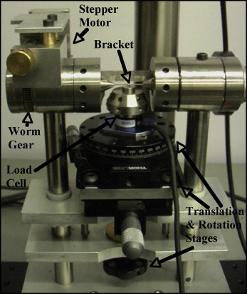
The torque measurement device, previously used by Badawi et al and modified for this study, is shown in Figure 1 . The key assemblies for measuring torque and angle are the wire and motor assembly and the load cell assembly. The modified load cell assembly consists of 2 translational stages and 1 rotational stage (Thorlabs, Newton, NJ), a 6-axis load cell (ATI Industrial Automation Nano 17 Multi-Axis force/torque transducer, Apex, NC), and the bracket mount on which sits the orthodontic bracket. Through the mount, the load cell measures forces and moments at the bracket slot. By using a FaroArm (FARO USA, Lake Mary, Fla) to determine the location of the bracket slot in relation to the designed load cell origin, a transformation is applied to the data so that the final data set of forces and moments are those at the slot of the bracket. By using the left-hand rule for torque ( T ) direction, the transformation equation is
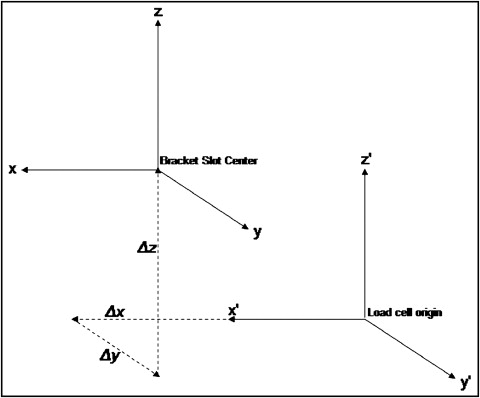
where the x direction is the parallel to the long axis of the wire and bracket slot, the z direction is vertical against the bracket base, and the y direction is perpendicular to both x and z, with the origin at the bracket slot center. X′ , y′ , and z′ are the equivalent coordinates, but with the origin located at the load cell. The measured distances between the load cell origin and the slot center, Δx , Δy , and Δz , are shown in Figure 2 . The left-hand rule is used for torque direction in the equation to match the coordinate calibration output from the load cell. The 3-dimensional Cartesian (x′, y′, and z′) force and moment data are collected through a data acquisition card (DAC 16-bit E series NI PCI-6033E, National Instruments, Austin, Tex) and logged with commercial software (LabWindows CVI, National Instruments). The data are exported to a spreadsheet, and the transformation is applied so that the final data output of torque is at the slot center.
The motor and wire assembly consists of 2 dies with rectangular slots that clamp tightly onto 0.019 × 0.025-in stainless steel orthodontic wire (Ormco, Orange, Calif). The distance between the 2 fixing dies was 15 mm. The entire wire assembly was rotated by a worm gear stepper motor (Cool Muscle CM1-C-11L30, Myostat Motion Control, Newmarket, Ontario, Canada). The stepper motor was controlled by custom software, and the angle was accurately measured by using the motor’s internal control loop at any time.
After the wires were tightened into the dies, they were dropped into the bracket slot at the initially estimated zero position. By using the translation and rotation stages, the forces were zeroed within 0.01 N in the y and z directions by using the 2 translational stages, and the moments were zeroed to within 0.08 Nmm in the z direction by using the rotational stage. Preload forces in the x direction cannot be easily controlled and reach a maximum of 0.3 N. However, the x-direction forces have no direct impact on T x , as can be seen in the equation. Preload torque in the y direction cannot be controlled, because it depends on the bracket manufacturing tolerances and how the adhesive sets between the bracket and the mounting cylinder. Since T y does not appear in the equation, it is assumed to have little impact on T x . Because it is not possible to accurately determine the zero position, the wire is rotated into the starting position, –15° from the estimated zero position, followed by a 78° rotation forward from this position to a maximum of 63° and then returned to the starting position. Force and moment data are logged every 3° during the tests; data are thus collected between –15° and 63°.
Three types of 0.022-in slot self-ligating brackets were used: Damon Q (Ormco), In-Ovation-R (GAC, Bohemia, NY), and Speed (Strite Industries, Cambridge, Ontario, Canada). The sample size was determined from previous data published by Badawi et al to be 30 for each bracket type. The brackets were numbered and randomly tested. A new section of wire was used for each test.
In this article, we report standard deviations and use descriptive statistics in the discussion. The use of these statistics is supported by testing the data for normality with the Kolmogorov-Smirnov test. To determine whether there was a statistically significant difference between brackets, a statistical package (version 17.0, SPSS, Chicago, Ill) was used to carry out analysis of variance (ANOVA). Since the equal variance assumption for ANOVA was violated, the test statistics were obtained by using the Brown-Forsythe and Welch methods at each angle. If the P value based on the Brown-Forsythe and Welch methods was greater than 0.05, all comparisons among the brackets at that angle were considered to have no statistically significant difference. The post-hoc multiple comparisons were performed at the angles where the statistical difference was detected from ANOVA at the significance level of 0.05. There were 5 post-hoc tests to make pairwise comparisons among 3 types of brackets, and the significance level was determined as 0.05/5 = 0.01. That is, comparisons with P values less than 0.01 were considered statistically significant.
Results
Torque vs wire twist angles for the Damon, In-Ovation R, and Speed brackets are shown in Figure 3 . Each experiment started at –15° on the line labeled “increasing angle.” At each 3° increment, a new data point was taken as the angle was increased. At 63°, the angle reached a maximum and then was decreased, with torque measurements taken every 3°. The line of decreasing angle, which for all 3 brackets had a lower torque than the increasing line, also took points every 3° from 63° to –15°. The error bars represent ± 1 SD (68% CI). The shape of the curves was similar between Damon ( Fig 3 , a ) and In-Ovation R ( Fig 3 , b ). The average torque expression for Speed brackets reached a plateau at approximately 50° of positive wire twist and then declined.
A number of Speed ( Fig 3 , c ) brackets (16 of 30) reached maximum torque before 63°, usually followed within a few degrees by a sudden loss of torque. Figure 4 shows an example of this phenomenon for 1 bracket. Table I shows the value of maximum torque for each bracket that had a premature torque peak. This was the reason that the standard deviation increased substantially in Figure 3 , ( c ), at a torquing angle of 48° to 63°. Figure 5 shows the Speed torque expression for the 14 brackets that did not have a premature torque peak and, presumably, whose bracket doors did not open. Speed brackets that do not have a premature maximum torque have similar torque curves as Damon and In-Ovation R brackets. Unless otherwise indicated, the 14 Speed brackets with no premature torque peak were called “Speed-NTP,” and the full sample of 30 brackets was called simply “Speed.”


