Key points
- •
Recent advances in imaging systems, software, and the use of additive manufacturing techniques have provided unprecedented opportunities for evaluation of both hard and soft tissues for presurgical planning, custom implant fabrications, and surgical guides.
- •
Standardization of the medical image files as digital imaging and communications in medicine (DICOM) has made possible the development of software that can evaluate, manipulate, and reformat medical images that make them easily converted to file formats to fabricate medical models and custom devices from industrial manufacturing processes.
- •
These standards are applied to all medical capture devices to include magnetic resonance, ultrasound, conventional computed tomography (CT) scans, and dental cone beam CT (CBCT) ensuring that all of these files are compatible with picture archiving and communication systems, which store and provide access from multiple modalities.
Cephalometric radiographs, pantographic radiographs, and computed tomography (CT) have historically been used for imaging for reconstruction of the craniofacial structures. The development of 3-dimensional (3D) rendering algorithms of the viewing software for medical images provided the information to allow surgeons the ability to better visualize boney and soft tissue defects. In addition, standardization of the medical image files as digital imaging and communications in medicine (DICOM) has made possible the development of software that can evaluate, manipulate, and reformat medical images that make them easily converted to file formats to fabricate medical models and custom devices from industrial manufacturing processes. These standards are applied to all medical capture devices to include magnetic resonance, ultrasound, conventional computed tomography (CT) scans, and dental cone beam CT (CBCT) ensuring all of these files are compatible with picture archiving and communication systems (PACS), which store and provide access from multiple modalities. Recent advances in imaging systems, software, and the use of additive manufacturing techniques have provided unprecedented opportunities for evaluation of both hard and soft tissues for presurgical planning, custom implant fabrications, and surgical guides.
The goal of this article is to introduce the following concepts and how they provide craniofacial reconstruction:
- •
Radiographic imaging systems used in head and neck reconstruction
- •
3D surface imaging (stereophotogrammetry)
- •
3D software reconstructions and virtual surgical techniques
- •
Custom reconstruction techniques
Radiographic images
CT
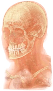
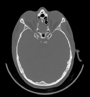
CT generates internal and external anatomic views by a radiographic approach ( Fig. 1 ). A 1-dimensional (slice or fan-shaped) beam of x-ray radiation is directed through the subject. Radiodense tissues block some of the x-ray photons, and the transmitted photons are detected on the opposite side of the subject. The x-ray emitter and x-ray detector oppose each other on a rotating ring. As the ring rotates around the subject, a 1-dimensional (1D) radiographic dataset is obtained. The 1D dataset is mathematically transformed into a 2-dimensional (2D) radiographic view in the plane of the ring. This 2D view is a single slice of finite thickness. The ring is axially traversed to a new location along the long axis of the subject and the process is repeated to obtain additional 2D slice images. A set of 2D sliced images normal to a traversing axis, taken at known locations, forms a tomographic dataset. The tomographic dataset can be visualized in 3 dimensions, showing a view of the internal anatomy in reference to the external anatomy, as shown in the accompanying image ( Fig. 1 ). In a typical CT slice image of the head, bone is easily discerned from soft tissue, where high radiodensity tissues display brighter than lower radiodensity tissues, and air displays black ( Fig. 2 ).
Tomographic slices are stored as digital grayscale images. Each pixel has a calibrated, known size; the matrix of pixels defines the area covered by the slice. The grayscale value of each pixel is encoded to the x-ray radiodensity of the tissue at that spatial location. Grayscale values in medical CT images are calibrated to the Hounsfield Unit scale (HU), where distinct tissue types have definite HU value ranges. A tomographic slice represents a finite thickness slice through the anatomy, and the spacing between each image slice is known; thus, each pixel can be assigned a thickness to become a 3D element, or a voxel. Medical CT voxels are generally orthotropic, being taller than the width or depth.
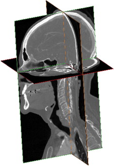
Axial slice sets can be reformatted and displayed as coronal, sagittal, or oblique slice views by displaying the projection of voxels along any plane of interest. Fig. 3 shows a combination of orthogonal views generated from an axial tomographic dataset. In cases of large slice distances, orthotropic voxels may cause the image to appear distorted or saw-toothed in transverse projections.
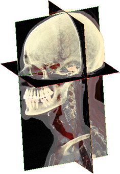
Three-dimensional views of the anatomy are generated assigning color and opacity values to the voxels and displaying the projection along a defined viewing direction. In the volumetric rendering, tissues are visually contrasted by unique color and opacity values assigned based on the HU value of the voxel ( Fig. 4 ). Individual anatomic structures can be segmented from the dataset by grouping and displaying only voxels in a desired HU values range. Typically, hard tissue structures are readily differentiated from soft tissue, but soft tissue types are not as readily differentiated.
Radiopaque objects in the field of the CT slice will cause streak artifacts in the image ( Fig. 5 ). Dental restorations, dental implants, bone-mending plates, screws, vascular clips, and shrapnel can cause streaks in the image, which occlude the view of the anatomy. However, these artifacts are limited to slice plane(s) containing the radiopaque objects. Metal artifact reduction algorithms are often applied during the construction of the slice image to reduce distortion. Careful segmentation of a CT scan of a cadaver skull with metal spheres demonstrates that the metal artifacts can be minimized in the 3D model construction. Small streak artifacts can still be noted on the sphere near the mastoid process and on the posterior of the skull ( Fig. 6 ).
Medical CT scan radiation exposure to tissues of the head can be significant. Radiation dose for a maxillofacial scan has been reported in the range of 534 to 860 μSv effective dose.
CBCT
CBCT is an alternate radiographic imaging approach to obtain a tomographic dataset of the head. This modality is typically used to support dental treatment, especially in planning dental implant placement.
CBCT differs from CT in that the entire volume of the field of view is captured in a single rotation of the x-ray emitter and detector around the subject. In this case, multiple 2D x-ray image projections are collected, at radial intervals around the head. The set of 2D images are mathematically transformed to a 3D voxel data set. The volume data are then stored as a set of 2D slices images at regular intervals.
A direct comparison of CBCT to multidetector CT (MDCT) image quality can be seen in Figs. 7 and 8 , each from approximately the same axial location on the same subject; Fig. 7 is from a large-field CBCT scan, whereas Fig. 8 is from an MDCT scan. Contrast between tissue structures is generally lower in the CBCT scan. Furthermore, it can be noted that the gray value of bone is inconsistent, varying with location in the CBCT slice. The latter effect is caused by beam-hardening artifact. Because of the severity of the beam-hardening effect, the CBCT cannot be calibrated to the Hounsfield Unit Scale.
Disadvantages of CBCT:
- •
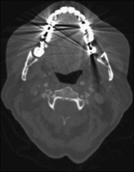
Metal streak artifacts and image noise are generally more severe in CBCT scans. Fig. 9 shows the effect of multiple dental restorations in a CBCT scan slice. The radiating light and dark streaks are similar to the medical CT image, except the starburst effect is present throughout the image. Fig. 10 shows similar effects from a bone-anchored hearing aid (in the lower left corner of the slice).
Fig. 9 Dental restoration artifact in CBCT.Fig. 10 Streak artifact from bone-anchored device in CBCT. - •
Truncation artifacts, or streaks radiating from the edges of features with differing radiodensity, are very prevalent in CBCT images.
- •
A gray value noise similar to analog television static is also prevalent in the images.
Advantages of CBCT:
- •
CBCT images have an advantage of high resolution, generally higher pixel resolution than most medical CT devices.
- •
CBCT slice thickness is generally identical to the pixel dimensions resulting in cubic (or isotropic) voxel. Isotropic data can be reformatted along any plane with minimal distortion in the image.
- •
CBCT scans are inexpensive and take only about 30 to 60 seconds to complete.
- •
The CBCT generally has the advantage of a significantly lower radiation dose for a maxillofacial scan, in the range of 70 to 98 μSv effective dose depending on the device; however, a few outlier devices can rival the radiation dose reported for an MDCT scan.
Magnetic resonance imagery
Magnetic resonance images (MRI) are an imaging modality that provides an internal view of the anatomy without exposing the subject to x-ray radiation. Images are generated from the reaction of hydrogen atoms in tissues interacting with a strong magnetic field. The greater the number of hydrogen atoms present, the stronger the induced signal from that tissue.
Magnetic field changes caused by the moving hydrogen atoms induce currents in a receiver coil. Similar to the CT scan principle, 1D data from the coil is transformed into a 2D slice, and encoded as gray value pixels in a digital image matrix ( Figs. 11 and 12 ).
Disadvantages:
- •
Bone does not provide a return signal.
- •
High-resolution scans take a long time and are usually degraded by subject movement.
- •
Slice thickness and spacing are generally much larger than CT or CBCT scans.
- •
Coil sensitivity is not uniform; grayscale values can shift from position to position in the image.
- •
Images can be distorted by a number of artifacts resulting from radiofrequency radiation patterns.
- •
Cannot scan patients with ferrous metal implants.
Advantages:
- •
No radiation exposure to the patient
- •
High slice plane resolution
- •
Excellent soft tissue differentiation
Radiographic images
CT
CT generates internal and external anatomic views by a radiographic approach ( Fig. 1 ). A 1-dimensional (slice or fan-shaped) beam of x-ray radiation is directed through the subject. Radiodense tissues block some of the x-ray photons, and the transmitted photons are detected on the opposite side of the subject. The x-ray emitter and x-ray detector oppose each other on a rotating ring. As the ring rotates around the subject, a 1-dimensional (1D) radiographic dataset is obtained. The 1D dataset is mathematically transformed into a 2-dimensional (2D) radiographic view in the plane of the ring. This 2D view is a single slice of finite thickness. The ring is axially traversed to a new location along the long axis of the subject and the process is repeated to obtain additional 2D slice images. A set of 2D sliced images normal to a traversing axis, taken at known locations, forms a tomographic dataset. The tomographic dataset can be visualized in 3 dimensions, showing a view of the internal anatomy in reference to the external anatomy, as shown in the accompanying image ( Fig. 1 ). In a typical CT slice image of the head, bone is easily discerned from soft tissue, where high radiodensity tissues display brighter than lower radiodensity tissues, and air displays black ( Fig. 2 ).
Stay updated, free dental videos. Join our Telegram channel
VIDEdental - Online dental courses


