11
Instrument Set and Equipment
In this chapter, we examine the armamentarium for dental local anesthesia, mainly needles, cartridges, syringes, and other instruments.
Needles
Needles enable the local anesthetic solution to pass from the cartridge to the tissues surrounding the tip. Current dental needles are disposable (single‐use) and double‐tipped for use in cartridge‐type syringes (ISO 7885: 2010). They were introduced in 1959 (Dobbs 1965) and the early 1960s (Bedrock et al. 1999; Pogrel 2009), and are recommended for use in dentistry by the Council on Dental Materials and Devices of the American Dental Association (ADA) (Alling and Christopher 1974). This type of needle has the advantage that it resolves some of the older problems (Alling and Christopher 1974), namely, loss of sharpness and barbing owing to repeated use, breakage of the needle owing to metal fatigue, and cross‐infection resulting from the needle being used in more than one patient.
Needles come in individual wrappers and are sealed with protective caps that maintain the sterility ensured during manufacture using ethylene oxide or gamma irradiation (Oikarinen and Perkki 1975a; Council on Dental Materials 1986).
Needles are made of flexible stainless steel (18/8 type) to prevent them from breaking if bent. According to the manufacturer, the metal contains up to 17 compounds, the most important being iron, chrome, and nickel (Oikarinen and Perkki 1975a). It is important to note that the manufacturing technique and the composition can affect the characteristics of rigidity and deflection (Robinson et al. 1984; Van der Bijl and Rossouw 1996).
Modern disposable dental needles of all lengths and gauges are very resistant to breakage resulting from traction or bending and easily exceed safety standards (Oikarinen and Perkki 1975a; Cooley and Robinson 1979; Robinson et al. 1984; Van der Bijl and Rossouw 1996; Tomas et al. 2000). Nonetheless, it is important to note the following: (i) the finest 30G needles are weaker than thicker gauges (27 and 25G) (Oikarinen and Perkki 1975a; Robinson et al. 1984; Tomas et al. 2000; Pietruszka et al. 1986; Bhatia and Bounds 1998; Zelster et al. 2002) and (ii) the hub is the weakest part of the needle and the point where most break (Pietruszka et al. 1986; Bhatia and Bounds 1998; Zelster et al. 2002).
Parts of a Needle
Modern double‐tipped disposable needles comprise the following parts (Figure 11.1).
Anterior Part
This is the active part of the needle, which penetrates the tissues and is in turn made up of the following:
- The shaft, or shank. This is the external part, which is characterized by being very polished and smooth (Van der Bijl 1995), as well as being covered by a thin layer of silicone to ensure that the shaft passes easily through the tissue with the least resistance, thus making the insertion less painful (Winther and Petersen 1979; Van der Bijl 1995). The silicone layer also helps to prevent oxidation of the metallic surface (Van der Bijl 1995).
- Tip. Current needle tips are tribevel with an eccentric bevel on one side, a main bevel, and two secondary bevels on the beveled surface of the main bevel (Figure 11.2). This modern concept is based on multibevel tips or scalpel points ensure the best possible edge and reduce the force of penetration, thus decreasing pain and injury in the mucosa and tissues (Winther and Petersen 1979; Lehtinen and Oksala 1979). The bevel angles are also shallow (9–12°) to reduce deflection as the needle crosses the tissues (Aldous 1968; Robinson et al. 1984; Stacy and Hajjar 1994; Meechan 2002).
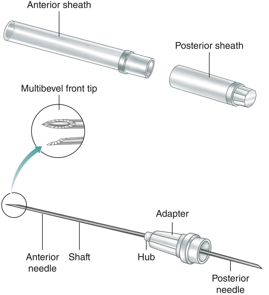
Figure 11.1 Parts of a disposable double‐tip needle.
Source: Redrawn with modifications from Jastak et al. (1995).
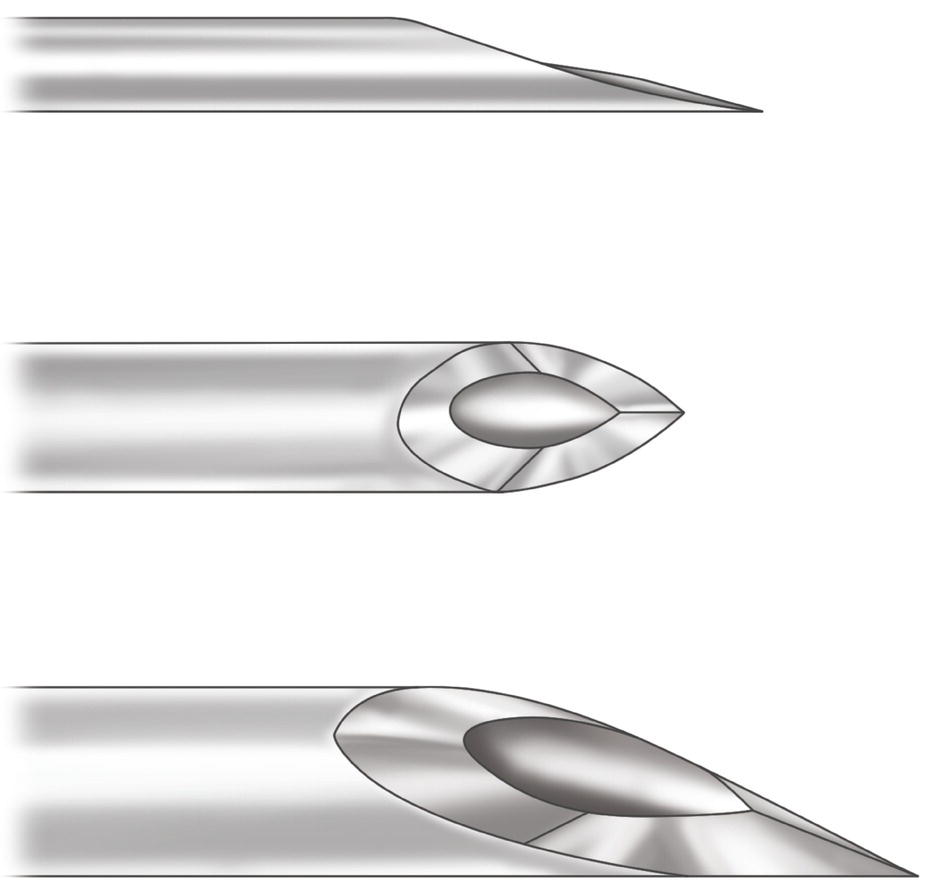
Figure 11.2 Multibevel tip of double‐tip disposable needles.
It is interesting to observe that once injected, the anesthetic solution spreads around the tip of the needle in an oval, with approximately equal quantities on both sides of the bevel.
Middle Part
This part is in turn composed of two parts, the hub and the socket (adapter).
- The hub separates the anterior part of the needle from the posterior part. It is the weakest part and the point where the needle usually breaks, therefore the needle must never be completely inserted into the tissues up to the hub (Pietruszka et al. 1986; Bhatia and Bounds 1998; Zelster et al. 2002).
- The socket, or adapter, is the point where the needle is attached to the mouth of a cartridge‐type syringe. Plastic sockets lack an internal thread. The thread is created by screwing the socket onto the threaded mouth of the syringe. Metallic sockets are already threaded. Many manufacturers place a triangle or arrow or some other mark on the socket to help the dentist align the needle with the bevel.
Posterior Part
This is a shorter needle (17–25 mm) that perforates the diaphragm of the cartridge and is located inside the syringe. Its tip is beveled at a steeper angle (15–55°) (Meechan 2002). Manufacturers sometimes make the back part of the needle too short, in which case it does not perforate the diaphragm of the cartridge, or too long, thus leaving anesthetic solution inside the cartridge because the plunger cannot reach the final stage owing to its contact with the posterior part of the excessively long needle.
Of note, the lumen of the needle has a rough surface (Oikarinen and Perkki 1975a) (Figure 11.3) and a larger lumen does not make injections less painful (McPherson et al. 2015).
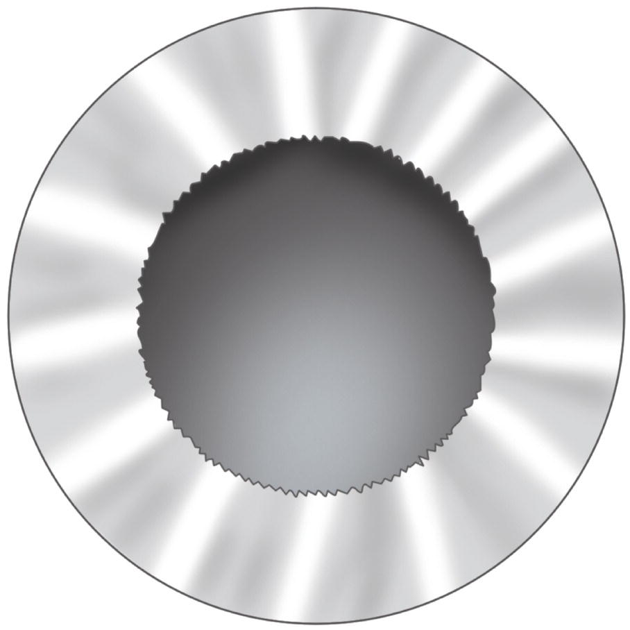
Figure 11.3 Lumen of the needles with an irregular surface.
Source: Drawn from Oikarinen and Perkki (1975a).
Protective Sheath
This is the sheath that keeps the needle sterile and sealed. It is formed by two protective caps:
- The anterior cap, which covers the front, or active, part of the needle and is fitted to the socket or adapter.
- The posterior cap, which covers the short posterior needle and is fitted to the socket or adapter. At the same time, it overlies the anterior cap so that it is the first part to be removed when the seal is broken. The needle can be screwed into the anterior part or needle adapter of the syringe, while the anterior part of the needle remains covered and is protected.
Where the protective caps join, at the level of the adapter, there is a label showing the gauge, length, manufacturer, and expiry date of the needle (Meechan 2002).
Lengths and Gauges
As we shall see, length and gauge (G) play a key role in the selection of needles for the various anesthetic techniques.
Table 11.1 shows the different lengths of needle in the active (anterior) part, which is that running from the hub to the tip. As we can see, there are three lengths – long, short, and extrashort – although each varies depending on the manufacturer. However, the most widely used lengths at present are shown.
The gauges used during the first half of the twentieth century were thick (20 or 23G), although after the Second World War new needles appeared. These were made of stainless steel and were much more resistant and flexible, therefore the gauge could be reduced to 25G (Harrison 1948). Each gauge has an external diameter (gauge) and an internal diameter (lumen): the smaller the gauge number, the thicker the external and internal diameters of the needle (Table 11.2). The main gauges used at present are 25, 27, and 30G. However, by far the most widely used is 27G (Alling and Christopher 1974).
Table 11.1 Lengths of needles.
| Length | ||
|---|---|---|
| Type | Millimeters | Inches |
| Long | 41 | 15/8 |
| 38 | 1½ | |
| 35 | 1 3/8 | |
| 30 | 1 1/8 | |
| Short | 25 | 1 |
| 20 | ¾ | |
| Extra‐short | 12 | ½ |
| 10 | — | |
| 8 | 1/3 | |
The most common gauges used in dentistry are shown in bold.
Needles: Critical Aspects
Needles are subject to limitations that should be clarified to facilitate appropriate choice and use.
Table 11.2 Needle gauges.
Source: Data from Oikarinen and Perkki (1975a), Council on Dental Materials and Devices (1978), Trapp and Davies (1980), Lehtinen (1983), Jastak et al. (1995), Meechan (2002), Malamed (2004), Gaudy and Arreto (2005), and ISO 7885 (2010).
| International | Gauge | External diameter | Internal diameter | ||
|---|---|---|---|---|---|
| gauge | France | Millimeters | Inches | Millimeters | Inches |
| 20G | 90/100 | 0.90 | 0.360 | — | — |
| 22G | 70/100 | 0.70 | 0.280 | — | — |
| 23G | 60/100 | 0.60 | 0.024 | 0.30 | 0.012 |
| 25G | 50/100 | 0.50 | 0.020 | 0.25 | 0.010 |
| 26G | 45/100 | 0.45 | 0.018 | 0.25 | 0.010 |
| 27G | 40/100 | 0.40 | 0.016 | 0.20 | 0.008 |
| 28G | 35/100 | 0.35 | 0.014 | 0.20 | 0.008 |
| 30G | 30/100 | 0.30 | 0.012 | 0.15 | 0.006 |
| 32G | 26/100 | 0.26 | 0.010 | — | — |
The most common gauges used in dentistry are shown in bold.
Aspiration and Gauge
Poiseuille’s law describes the relationship between diameter and resistance to flow of a liquid in a tube, intravenous catheter, or needle. The resistance to flow is inversely related to the radius to the fourth power. For example, if the internal diameter of the needle (lumen) is halved, the resistance to the flow of liquid inside the needle increases 16‐fold (Wittrock and Fischer 1968). Furthermore, as blood transports formed elements (red cells, lipoproteins, etc.) (Guyton 1976), it is three to four times more viscous and dense than water, with the result that resistance is greater.
Both in vitro studies (Smith 1968a, 1968b; Wittrock and Fischer 1968; Cooley and Robinson 1979; Piesold et al. 1998) and clinical studies (Cohen et al. 1969; Watson and Colman 1976; Trapp and Davies 1980; Brownbill et al. 1987) have shown that blood can be aspirated with fine, narrow gauges (30G) and thick gauges (25G). However, the narrowest gauges (30G) have a slow and reduced aspiration flow rate, since they must overcome higher flow pressure (Smith 1968a, 1968b; Cooley and Robinson 1979; Piesold et al. 1998). In addition, the evaluation of a true positive aspiration requires a sufficient volume of aspirated blood such that a color change is noted in the cartridge (Watson and Colman 1976). For this reason, it is not advisable to use 30G needles and we should use 27 and 25G needles to ensure that aspirated blood is present in sufficient quantities when a positive aspiration does indeed occur and can therefore be seen by the provider (Cooley and Robinson 1979; Piesold et al. 1998).
Pain and Gauge
Most dentists think that smaller calibers (30 and 27G) cause less pain during insertion and injection (Smith 1968a; Cooley and Robinson 1979; Mollen et al. 1981; Van der Bijl 1995). However, clinical studies indicate that there is little difference in the perception of pain; six clinical trials revealed no statistically significant differences in the pain produced by different gauges of needle (30, 27, and 25G) and a further two trials show that the finest 30G needle produces less pain than a 27G needle (Table 11.3). In any case, the differences are negligible (even if they are statistically significant, as in the latter two trials they were of minimal clinical relevance). With respect to needles, the truly important factors involved in injection pain are as follows:
- Design of the tip. This is possibly the most important factor (Lehtinen and Oksala 1979) and the reason why modern needles are multibevel (Lehtinen and Oksala 1979; Winther and Petersen 1979).
- The fine layer of silicone covering the surface of the shaft of the needle reduces resistance during insertion into tissue (Winther and Petersen 1979; Van der Bijl 1995).
Table 11.3 Clinical trials that compare the pain caused by dental injection with needles of various gauges.
| Nonsignificant results | Statistically significant results | ||
|---|---|---|---|
| Reference | Gauge | Reference | Gauge |
| Fuller et al. (1979) | 30G, 27G, 25G | Ram et al. (2007) | 30G, 27G |
| Mollen et al. (1981) | 27G, 25G | Ghasemi et al. (2014) | 30G, 27G |
| Lehtinen (1983) | 30G, 27G | ||
| Brownbill et al. (1987) | 30G, 25G | ||
| Carr and Horton (2001) | 27G, 25G | ||
| Flanagan et al. (2007) | 30G, 27G, 25G | ||
The gauges that produce the least pain are shown in bold.
As we shall see in Chapter 13, possibly the most important individual factor involved in pain during insertion and injection is the skill/technique of the dentist (Mollen et al. 1981; Saloum et al. 2000; Goodell et al. 2000; Ram and Peretz 2003; Nusstein and Beck 2003).
Deflection of the Needle and Gauge
Deep linear insertions (e.g. regional block, such as mandibular block) with cartridge‐type syringes and the palm‐thumb grasp (e.g. traditional technique) cause the needle to deflect as it advances owing to the quantity of tissue taken up by the lumen (Jeske and Boshart 1985). This deflection is toward the tip, that is, the side opposite the bevel (Cooley and Robinson 1979; Hochman and Friedman 2000). The factors affecting this deflection are as follows:
- Gauge. The thicker the gauge, the more rigid the needle is and the less likely it is to deflect (Aldous 1968; Robinson et al. 1984; Jeske and Boshart 1985; Van der Bijl and Rossouw 1996; Hochman and Friedman 2000), therefore 25G needles (the thickest) are recommended for regional block by specification no. 54 of the Council on Dental Materials, Instruments and Equipment of the ADA (Council on Dental Materials 1986), since these are the needles that are least likely to deflect.
- Length. The longer the needle is, the more likely it is to deflect (Aldous 1968; Van der Bijl 1995).
- Bevel. The greater the angle is, the more likely it is to deflect (Aldous 1968); this is why current bevels have shallow angles (9–18°) and the steep angles of previous versions are no longer used.
- Characteristics of the metal used and manufacturing techniques. Needles of the same gauge and length from different manufacturers deflect to different degrees (Robinson et al. 1984; Van der Bijl and Rossouw 1996).
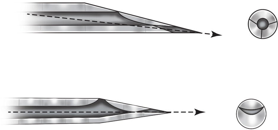
Figure 11.4 Tip of nondeflecting needles (Truject®) vs. conventional needles.
The currently marketed fine 28G Truject® needle is almost nondeflective during deep linear insertions owing to the design of the tip, which is centered on the longitudinal axis of the needle (Figure 11.4). This decreases the central area by 75%, thus reducing the amount of tissue taken up in the lumen as the needle advances (Jeske and Boshart 1985). The point of traditional needles is situated eccentrically; if it is placed more centrally, the needle is less likely to deflect (Aldous 1968).
Lesions Caused by a Barbed Needle
Repeated use in the same patient leads to loss of the edge at the tip in 80% of needles, thus causing tip of the needle to bend or barb (Oikarinen and Perkki 1975a). Barbing can be caused accidentally during preparation of the syringe (Jastak et al. 1995) – the most unusual cause – and during injection, when the needle meets the bone (Dentists’ Desk 1983; Jastak et al. 1995; Malamed 2004).
When a barbed needle is removed and/or inserted at another site (especially if the tip of the needle is deflected outwards), it can damage the muscles (causing trismus), the nerve stems (causing long‐lasting paresthesia), and the vessels (causing hemorrhage) (Stacy and Hajjar 1994).
It is difficult to see a barbed needle, although it is easily observed by wiping a sterile gauze across the tip, which catches in the material (Dentists’ Desk 1983; Jastak et al. 1995). A barbed needle should be discarded and a new one selected; hence the recommendation to change the needle after two to four injections (Dentists’ Desk 1983; Jastak et al. 1995; Malamed 2004).
Breakage of Needles
One of the main causes of needle breakage is the use of unsuitable needles in truncal block, owing to the depth of the insertion. It is important to note the following causes:
- The use of short needles that are inserted deep into the soft tissues as far as the hub, which is the weakest part, where the needle usually breaks (Pietruszka et al. 1986; Bhatia and Bounds 1998; Zelster et al. 2002). Around 50% of breakages in the dentist’s office occur in this situation (Annex 37).
- The use of fine‐gauge needles (30G), which are the weakest and have proven to be more fragile in vitro (Oikarinen and Perkki 1975a; Robinson et al. 1984). Around 60% of breakages in mandibular block involve needles of this gauge (Annex 37).
In conclusion, in regional block techniques such as mandibular block, it is not recommended to use short needles, fine‐gauge needles (e.g. 30G), or short and fine‐gauge needles, all of which account for more than 75% of cases of breakage (Annex 37).
Criteria for the Selection of Needles
Given the above, we can list practical criteria for selecting needles, depending on the technique and specific needs, as follows:
- Long 25G needles (the thickest) should be used for deep insertions in regional block, e.g. mandibular block, for several reasons:
- This is the gauge that is least likely to deflect during deep insertions.
- Aspiration is successful with 25G needles and in deep insertions positive aspirations are common.
- The injection is no more painful than with smaller gauges (27G or 30G), as shown in clinical trials.
- Short 27G needles should be used for infiltrative techniques that require little depth but successful aspiration, for two reasons:
- In these cases, a short needle is more comfortable than a long one.
- Aspiration is successful if a vessel is punctured.
- Short or extra‐short 30G needles are recommended in the following cases:
- When it is not necessary to aspirate, since their ability to reveal truly positive aspirations is very poor (see Chapter 13).
- When it is not necessary to inject deep into the tissue, since the needle deflects considerably more than with other gauges and is at greater risk of breakage.
Cartridges
The cartridge is a cylindrical tube that encloses the anesthetic solution between an opening sealed by a rubber diaphragm at the anterior part and a plunger, or plug, at the posterior part (Figure 11.5). Cartridges are disposable (a cartridge can only be used for one patient) and have several advantages:
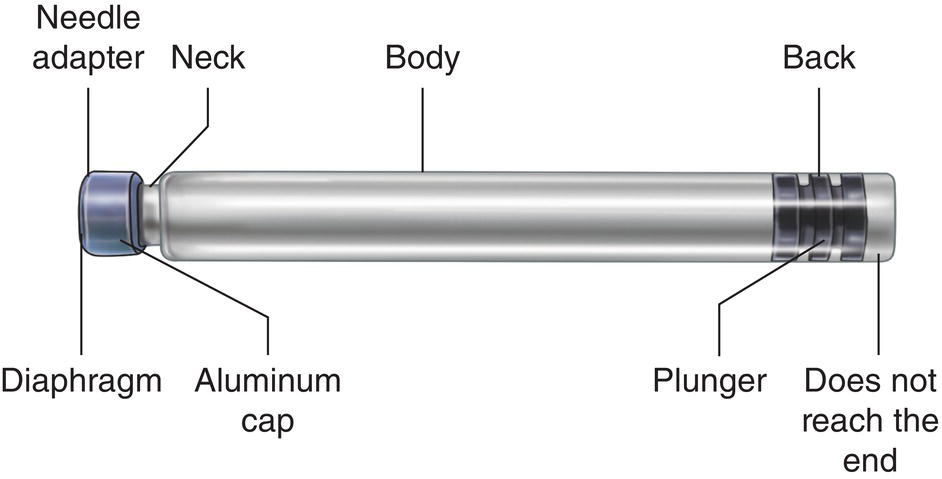
Figure 11.5 Parts of a cartridge.
- They guarantee the sterility of the anesthetic solution.
- They are easy and quick to load and clean. Modern cartridges do not require the dentist to break the ampule, draw up local anesthetic, and expel the air, therefore the dentist’s skin does not come into contact with the solution, which may spill during these maneuvers.
- They prevent contact with the metal of the syringe. Acidic solutions with epinephrine and other sympathomimetic vasoconstrictors interact with metals to release metal ions (nickel, zinc, copper) that irritate tissues and cause pain on injection, especially copper ions (Lundqvist et al. 1948).
Cartridges were introduced in 1920 by the army surgeon Harvey S. Cook, who compared them to a rifle cartridge, in the sense that one cartridge per patient is loaded and “fired” (Dobbs 1965). The Cook‐Waite company subsequently introduced the cartridge with the commercial name “Carpule”, which became so popular that many professionals today use the term “carpule” for all cartridges (Nevin and Putterbaugh 1949).
Cartridge volume is worthy of comment. Initially, cartridges contained 1, 2, and 2.5 ml (Nevin and Putterbaugh 1949). The 2‐ml cartridges contained 1.8 ml of anesthetic solution, with 0.2 ml taken up by the plunger. From 1950 onward, the standard 1.8‐ml cartridge became widely used (Gruber 1950). At present, use of these cartridges is standard practice throughout the world (Dentists’ Desk 1983; Malamed 2004). They measure 63–65 mm in length and 8–9 mm in diameter (Meechan 2002). The cartridges make it possible to inject up to 1.7 ml of anesthetic solution since the other 0.1 ml is trapped in the neck of the cartridge between the diaphragm and the plunger (Cannell et al. 1975).
Cartridges containing 2 and 2.2 ml are currently available, but only in certain countries, such as the United Kingdom and Australia. They are used less frequently because, being longer, holding the syringe is difficult when the dentist has small hands, thus hampering the aspiration maneuver.
The tube is made of one of two materials: (i) glass, which is better quality, with the result that most anesthetic solutions come in this type of container, and (ii) plastic, which is only used in some countries and is worse, for the following reasons:
- The plunger does not move as easily or as smoothly against plastic as against glass (Jastak et al. 1995; Malamed 2004).
- Plastic is less transparent, thus making it more difficult to evaluate positive aspirations (Jastak et al. 1995).
- Spills and leaks of solution are more common during injection than with glass cartridges (Malamed 2004).
- Resistance to pressure is half that of glass cartridges, therefore they are not recommended for the periodontal ligament technique (Table 18.2, Chapter 18). Plastic cartridges have the advantage that they do not break under pressure, but the tube becomes deformed and the anesthetic solution leaks out (Meechan et al. 1990).
Of particular interest is the fact that the diaphragm and the plunger contain small quantities of latex, therefore latex allergens may be present in the solution (Brown et al. 2002). However, to date there have been no reports of allergy to latex via local anesthetic cartridges (Shojaei and Haas 2002).
Parts of a Cartridge
Anterior Part or Needle Adapter
This part comprises the diaphragm, a fine latex membrane through which the needle penetrates, and the aluminum cap, which is generally silver in color and surrounds and holds the diaphragm to the needle adapter (Figure 11.5). The aluminum must not come into contact with the local anesthetic solution, since this can speed up the degradation of sympathomimetic vasoconstrictors such as epinephrine (Milano et al. 1982).
Neck
The needle adapter is joined to the body by a narrowing of the glass tube, where 0.1 ml of anesthetic solution is trapped and therefore cannot be injected (Cannell et al. 1975).
Cylindrical Body
The body is made of transparent glass in order to see blood clearly in positive aspirations and the volume injected via the movement of the plunger. The cylinder is the body of the syringe. As the plunger advances down the syringe pushed by the piston of the syringe, it can inject the solution via the needle.
Posterior Part
The posterior part contains the plunger or rubber stopper that is inside the cylindrical tube. This rubber stopper does not reach the end of the tube; if it does reach the end, then this could indicate that the solution is contaminated. The harpoon of the piston is attached to the rubber stopper and thus enables aspiration. Its main function is to move along the cylindrical tube pushed by the piston to inject the anesthetic solution.
The plunger may be solid, which is the most usual case, so that it can attach to the harpoon or the plunger support system. Less often, it is hollow to house a special system such as the blades of the Uniject® syringe (Meechan 2002).
Other Elements
- Silicone lubricant on the interior surface of the cylinder enables the plunger to slide smoothly along the glass tube. This lubricant was previously paraffin (wax) or glycerin. Both compounds could harden with time or with low ambient temperatures, thus creating resistance to the movement of the plunger or making it move along in fits and starts, especially at the beginning of the maneuver (blocked or sticky stopper).
- There is a transparent security foil on the surface of the cylinder. The foil serves the following purposes:
- To prevent pieces of glass falling into the patient’s mouth by limiting uncontrolled shattering of the cartridge if it breaks owing to excessive pressure during injection (e.g. during the periodontal ligament technique) (Rawson and Orr III 1985) or if it is cracked/split because of damage during transport (see Chapter 21).
- To facilitate administration of the exact volume of anesthesia by means of a line along the axis of the cartridge that acts as a volume indicator (graduated scale).
- To provide information on the name of the anesthetic solution and vasoconstrictor, concentrations, commercial name, lot number, and date of expiry.
- Content color code. This code may be a colored ring around the cylinder or the color of the rubber stopper or the aluminum cap at the needle adapter. A ring code system is used in the United States but not in Europe, where manufacturers have their own codes, therefore different brands can use the same colors on cartridges with different contents.
Storage of Cartridges
To ensure optimal performance with good preservation of the active ingredients, cartridges should be stored following a series of norms that can be divided in two groups: those that apply to all cartridges and those that also apply to cartridges containing sympathomimetic vasoconstrictors.
Norms for All Cartridges
- Store in their original packaging (Passon et al. 1992). Cartridges are not airtight compartments and may be contaminated by chemical vapors (Chasteen et al. 1988; Passon et al. 1992) via penetration of the rubber part of the diaphragm or the plunger (Passon et al. 1992); however, the package is completely closed and sealed.
Packages come in two formats: vacuum packed cans with 50 cartridges, which are rarely used today, and, more frequently, packages with five blister packs each containing 10 perfectly sealed and closed cartridges (the packages may also contain 10 blister packs).
- Store in a dry place, since humidity tends to deteriorate both the packages and the cartridges.
- Return damaged or deteriorated packages because the cartridges may be cracked or split and thus carry a risk of breakage during injection and/or loss of stability of the anesthetic solution (Meechan 2002; Malamed 2004). Cartridges should also be returned if the aluminum cap of the diaphragm in the needle adapter is dented or damaged, since the underlying glass may also be broken (Malamed 2004).
Cartridges should never be stored in the following ways:
- Submerged in disinfectant, since this can penetrate the cartridge and contaminate the anesthetic solution, leading to painful injections and long‐term paresthesia (Shannon and Feller 1972; Shannon and Wescottt 1974).
- Together with products that release chemical vapors, such as resin solvents, since these too can penetrate the cartridge (Chasteen et al. 1988; Passon et al. 1992).
Norms for Cartridges Containing Catecholamines
Sympathomimetic vasoconstrictors such as epinephrine, norepinephrine, and levonordefrin are all very sensitive to degradation, therefore the expiry date appears on the cartridge (Hondrum et al. 1993). In addition to the abovementioned norms, these cartridges are subject to additional storage conditions:
- Darkness, given that light speeds up oxidation of the vasoconstrictors, especially epinephrine. By light, we mean daylight (Gerke et al. 1977; Thoma and Struve 1986), fluorescent light in rooms (Hondrun and Ezell 1996), and ultraviolet light (Ciarlone and Fry 1980).
- The recommended storage temperature is 20–22 °C (68–72 °F), which is equivalent to ambient temperature, with minimum and maximum values of 15–30 °C (59–86 °F) (Hondrum et al. 1993). High temperatures speed up oxidation of the catecholamines and therefore their degradation (Fry and Ciarlone 1980; Kelly and Dalm 1985; Thoma and Struve 1986), thus cartridges should never be kept in cartridge warmers for long periods.
- Packages indicating that more than half of the lifetime of the drug has passed, that is 18 months, should be rejected before the expiry date (Dentists’ Desk 1983; Jastak et al. 1995), since the duration of the solution is 3 years. Solutions previously lasted for a shorter period when they were in good condition (Gerke et al. 1977
Stay updated, free dental videos. Join our Telegram channel
VIDEdental - Online dental courses


