Fig. 4.1.
A vertical cutter is used to prepare the channel for the threaded pin. At the same time this instrument prepares the ground for the lateral cutters to be used in the next step. The vertical cutter illustrated in this figure features FG tension at 1.6 mm and thus can be used with a turbine and high-speed contra-angle handpiece. The width of the working surface is also 1.6 mm. The cut width is thus smaller than the width of the threaded pin, which means that several cutting steps are required. Many users first apply a normal tungsten carbide cutter to expedite penetration of the hard cortical bone, which increases the lifespan of the vertical cutter. Note that the diameter of the vertical threaded pin is larger than 1.6 mm. This means that the slot has to be widened with the same instrument, which gives the operator a chance to slightly adjust the position of the slot and the vertical implant part
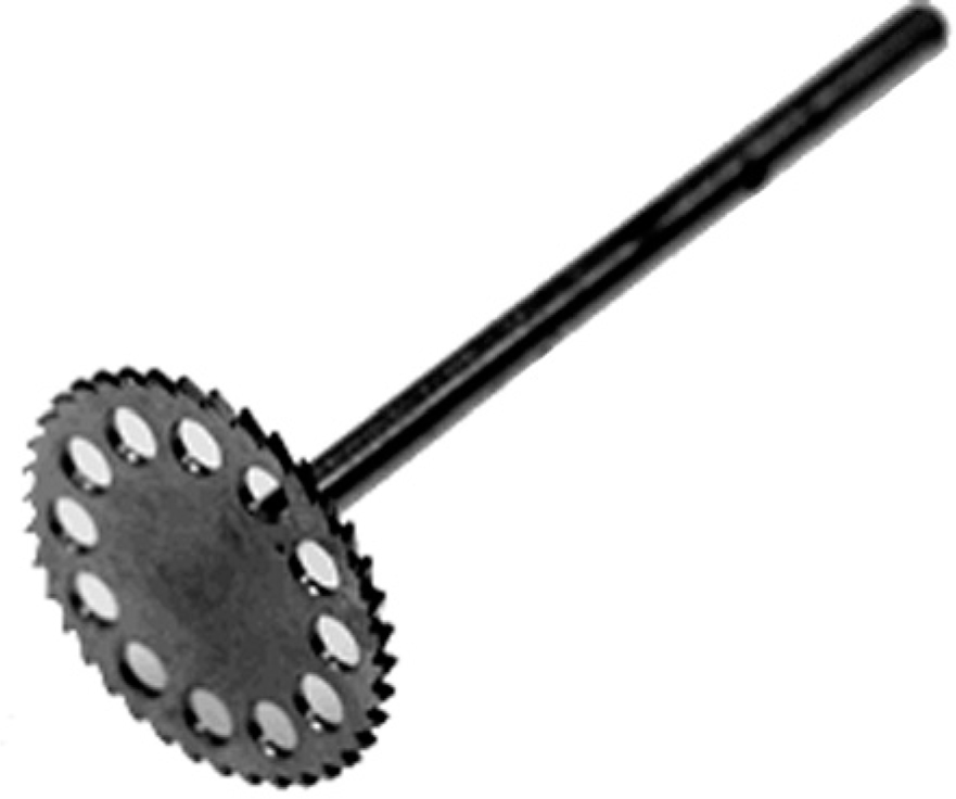
Fig. 4.2.
Lateral cutter (LC), 12 mm in diameter
The lateral cutter is used to create the horizontal dimension of the osteotomy. Several lateral cutters with incremental diameters are used successively, starting with 7 mm. The largest cutter currently available has a diameter of 15 mm. In softer tissue and with a good turbine engine, cutters with larger diameter might be used right away, so that the vertical size of the horizontal slot does not become too large.
Twin cutters are used for double-disk implants. Their function is twofold: they define the disk-to-disk distance, and they ensure that both cuts are parallel. Twin cutters are available in two diameters: the 9-mm or 7-mm types define a disk-to-disk distance of 5 mm or 3 mm, respectively.
The use of lateral cutters without cutting features along the shaft has the advantage that the horizontal osteotomy can be created more speedily. This presupposes, however, that the preceding vertical cut has been placed properly at right angles with the subsequent horizontal lateral cut. If that was not the case, a Combo cutter has to be used intermediately to create the required right angle between the vertical and the horizontal slot by «post-cutting» (adjusting) the vertical incision. Experienced implantologists usually have no problem placing both incisions correctly at right angles.
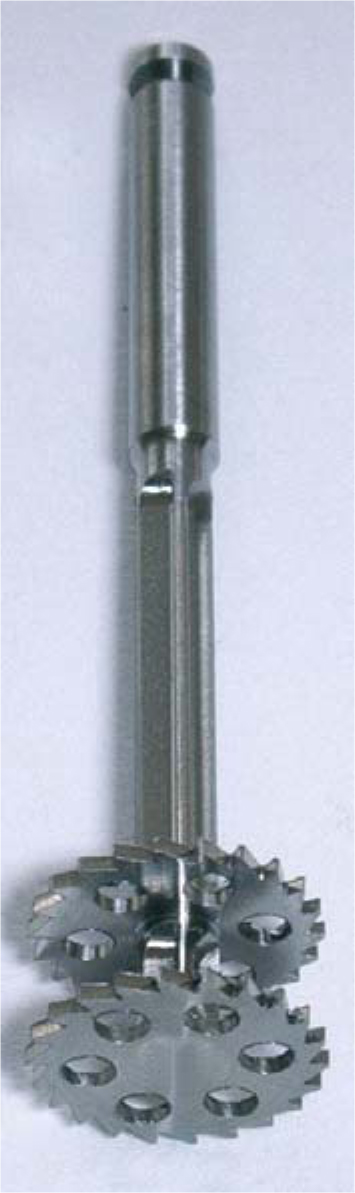
Fig. 4.3.
Twin (combi) cutter for two disks 7 mm in diameter that are 3 mm apart
As a certain disadvantage of all FG instruments, the chucks may clot up with blood introduced during the procedure, as the surgeon will not always be able to ensure the absence of any blood on the surfaces to be inserted into the turbine during surgery. Therefore, some users prefer to work with instruments to be inserted into the blue contra-angle handpiece (1:1) because these handpieces work without chucks. One disadvantage of contra-angle handpieces, however, is that the shaft cannot be reduced in length; it is therefore necessary to keep cutters with different shaft lengths in stock.
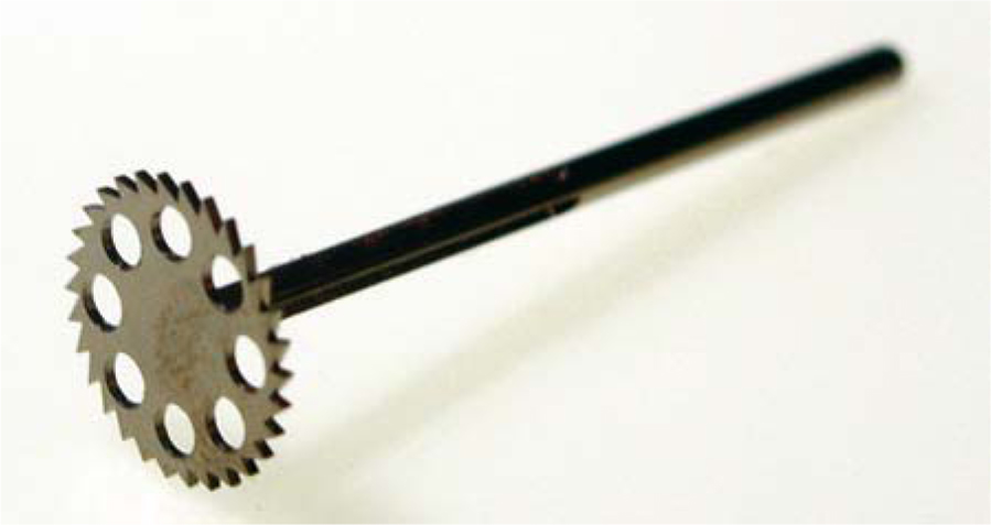
Fig. 4.4.
Combi cutter (KC), 10 mm in diameter, with cutting surfaces on both the disk and the shaft. These cutters are available with disk heights of 0.4 mm, 0.6 mm and 0.8 mm
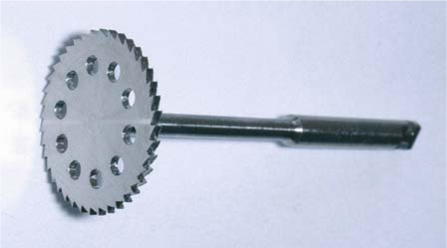
Fig. 4.5.
Lateral cutter (12 mm in diameter) for contra-angle handpiece
4.1.1 External Implants (ED)
As a rule, single-unit implants are really what the name suggests, i.e. they are made of a single ingot of titanium, using a high-precision (and high-cost) manufacturing technique.
These implants evolved from rotationally symmetrical designs with one or several load-transmitting surfaces. The size of these implants is given as base surface area or radius in mm. The height of the threaded pin is given in G units (1G=1.5 mm) and is measured from the upper margin of the base disk to the beginning of the thread, thus including the shoulder below the thread.
Designs with a semicircular base can be used to protect the implant against rotation within the osteotomy slot, the round side being inserted into the depth of the bone while the flat side borders on the bone laterally (i.e. medially and distally) and towards the vestibular aspect. These designs offer very good primary stability.
In many cases, the cortical bone structures in the maxilla and mandible are located 12–14 mm apart. As rotationally symmetrical designs cannot not be readily inserted in this situation, it is recommended to use lengthy BOI designs. The most appropriate design for this purpose is the EDAS implant (available as 9×12 mm, 9×14 mm, or 10×14 mm), EDADS implants (12/17 mm), or EDAAS implants (10×20 mm).
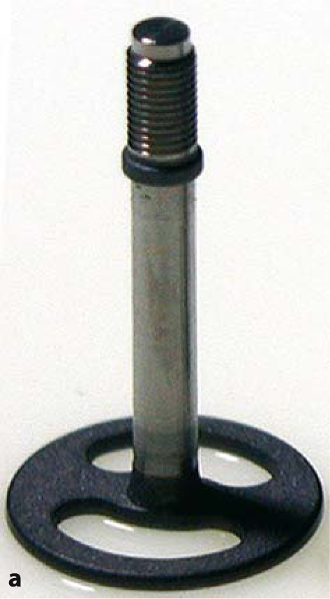
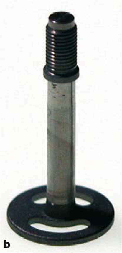
Fig. 4.6a,b.
ED 9G8 und ED 7G8. These two implant types are extremely popular, since the specific relationship between the disk diameter and the shaft length allows their application in a great number of clinical situations. These designs are also extremely reliable
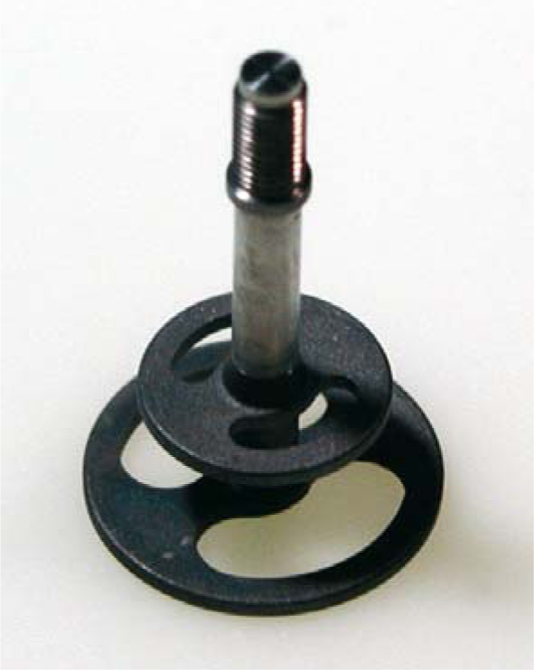
Fig. 4.7.
Double-disk implants 9/7 G5. The G5, G7 and G8 versions of these double-disk implants (9 or 10 mm diameter at the base disk) are commonly used to replace canines in both jaws
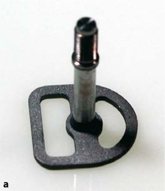
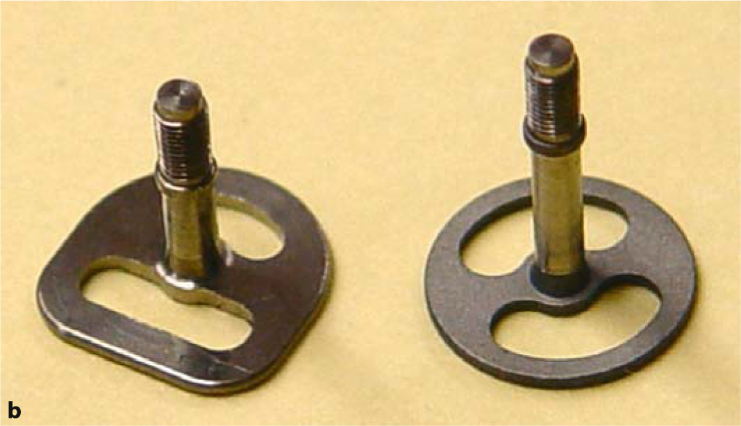
Fig. 4.8.
a EDS implants feature a basal plate that is basically circular but with a longer radius towards the angled ends. The implant is thus protected against rotation in the bone cavity. Furthermore, its lateral segments stabilize the implant against removing forces by increasing the friction. EDS 9G6 are used most commonly in the area of the second molars in the mandible. b A design with two additional edges offers much greater primary stability (and an intrabony anti-rotation feature) than a circular design with the same base diameter. Designs with edges an flat base-plates are called “S-Type implants”.
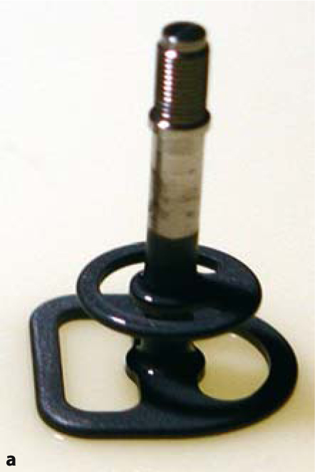
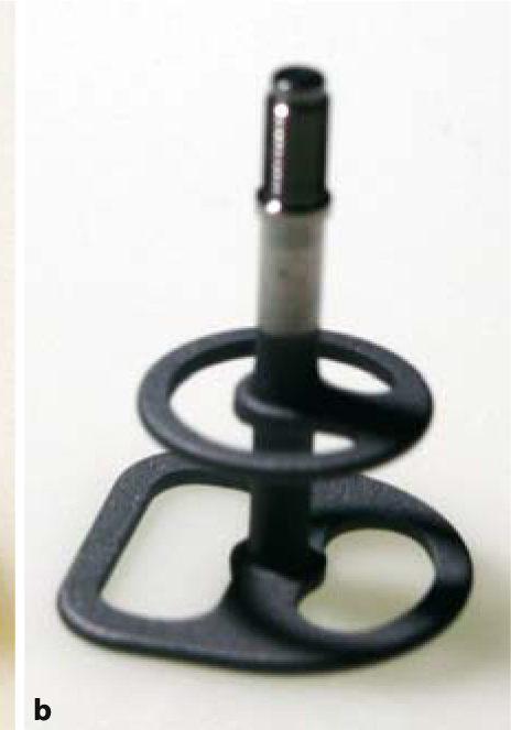
Fig. 4.9a,b.
EDDS implants (right) are well suited for insertion into stable bone structures. If the vertical bone volume is greater, it is recommended to use EXDDS implants (left), as the greater distance between the load-transmitting surfaces (5 mm) will prevent BMUs from interfering with each other during bone repair processes (see Chapter 23)
EDAAS implants feature one rounded and one flat side, but they are also available with two rounded sides. Maximum dimensions are 20 mm in width and 10 mm in height. Because the threaded pin invariably has to be centrally located during implant manufacture, titanium ingots with a diameter of over 30 mm would be required. In order to economize on the amount of titanium used in the manufacturing process, the threaded pin was shifted 2 mm from the centre of the circle in a medial direction, i.e. towards the centre of the implant. Available lengths range from G5 to G9.
The tendency of users to place fewer and fewer implants in each jaw is also reflected in the development of implant designs. Today’s Diskos implants, for instance, are characterized by a disk height of 0.6–0.8 mm. The materials used for this design include pure titanium (grade 1 or 2) and Ti15M0. For optimal fracture resistance, the radius in the transitional zone between the threaded pin and the web bar has been reinforced, and the web bar itself is also thicker as well. While these features allow for greater loading, it is nevertheless important to keep in mind that due to the elasticity of the bony implant beds, close osseoadaptation of all implant surfaces cannot be possibly attained in the presence of a high degree of mineralization. Thicker implants are less elastic than thinner implants made of the same material. This phenomenon becomes relevant mainly with implants transversing bone structures that are out of sync in terms of dislocation. Thicker implants are more likely to be selected when strategic implant positioning is planned.
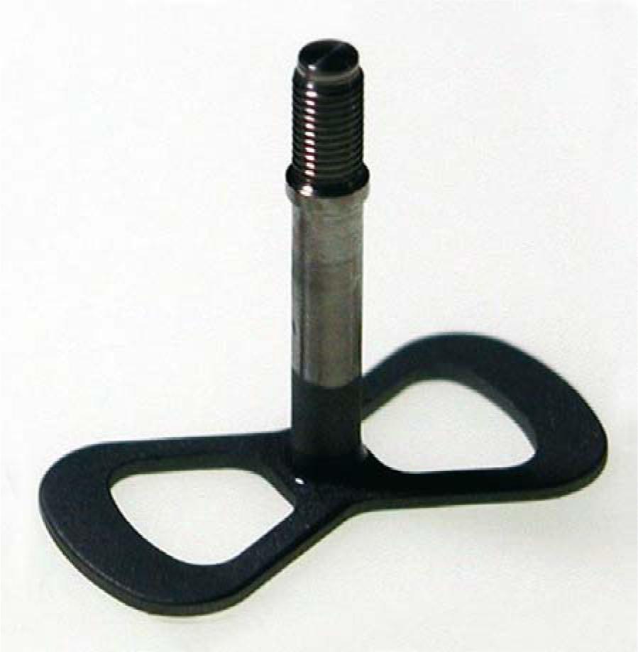
Fig. 4.10.
EDA implant (7×16 mm) with centrally located threaded pin
4.1.2 Abutments and Components for External-Thread Designs
The three abutment types in Fig. 4.16 are perfectly serviceable for most applications.
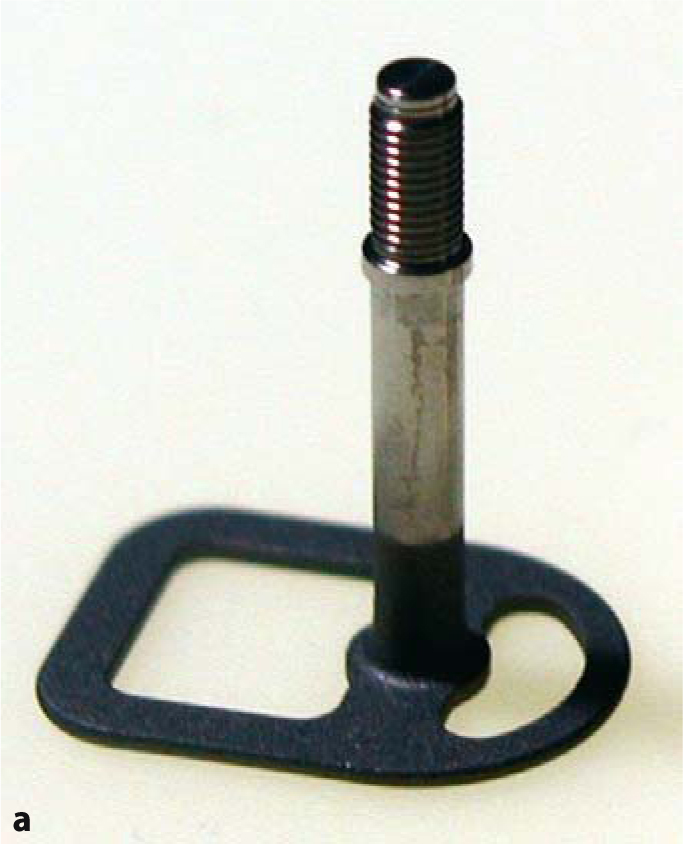
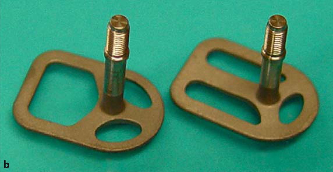
Fig. 4.11.
a EDAS 9/12 G5. This implant design is predominantly used in distal jaw segments. EDAS implants are also available with three web bars radiating from the threaded pin. b EDAS implants are also available with three web bars
The total height of these implant types is 6.5 mm for TSD4 and 10.5 mm for TDS5 and TSD99. The TSD99 abutments have a more internal/superior position of the internal threading as distinguishing feature, allowing longer implant shafts to be adjusted in a mucosal direction. The advantage of TSD99 abutments is that they offer a very long surface for cementing even on ED implants whose thread is located in a very high position. Frequently, abutments on long threaded pins have to be reduced down to the thread, which would bring the length available for cementing down to the thread length of roughly 3–5 mm. Deficits of this type can be easily eliminated by using TSD99 abutments, which will increase the available surface for cementation by another 4 mm in mucosal direction. Nevertheless, care must be taken that no direct contact to the mucosa is established, since the apron-style coverage tends to favour retention of food remnants. It is frequently a good idea to decide on using longer threaded pins during the procedure and compensate for the increased length by using TSD99 abutments for the prosthetic superstructure. In situations where the threaded pin is located in a sloped mucosal area, the TSD99 abutment and the spaces in the superstructure designed to hold them can be reduced obliquely.
The same abutment types are also available in white Delrin. These designs are more elastic, a feature is preferred by many BOI users. DA abutments can be bonded with glass-ionomer cement to obtain a semi-permanent connection that is stable yet allows de-bonding in a relatively simple manner if the need arises. Combined with cements like Panavia, they may be used for definitive cementation. Delrin abutments are unsuited if the BOI is to be flexed for angulation because they are liable to break in this specific situation. Instead, it is better to use titanium abutments or the TAP-D tool (screwed onto the thread) for this type of manipulation (see Video 7).
Stay updated, free dental videos. Join our Telegram channel
VIDEdental - Online dental courses


