Fig. 10.1
(a) Inlay/onlay dimensions for E-max (printed with the permission of Ivoclar Vivadent). (b) Anterior and posterior crown dimensions (printed with the permission of Ivoclar Vivadent). (c) Bridge span (Printed with the permission of Ivoclar Vivadent). (d) Veneer dimensions (Printed with the permission of Ivoclar Vivadent)
10.2 Tooth Preparation Guidelines for CAD/CAM Technology
-
Prior to tooth preparation and anesthetizing the patient, select a shade. This avoids desiccation of the tooth and improper matching of the shade for the final restoration.
10.2.1 Pearls for Tooth Preparation for All-Ceramic Restorations
-
Armamentarium selection facilitates preparation of the tooth surface for all ceramic restorations. Several companies have a select set of burs that help accomplish the goals (Fig. 10.2).
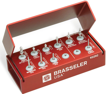 Fig. 10.2Many companies manufacture burs specifically for preparation of teeth for all ceramic crowns
 -
More often than not, occlusal reduction should be the first step in preparing the tooth to avoid excessive removal of tooth structure. Depth cuts on the occlusal with the proper burs ensure that the proper occlusal clearance is obtained for your material of choice (Fig. 10.3).
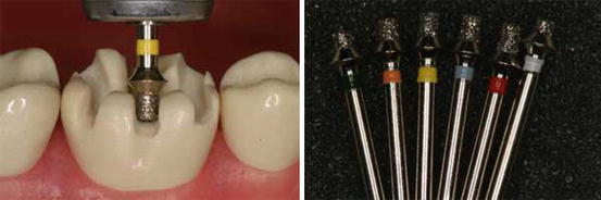 Fig. 10.3Depth cut burs are a good way to mark proper reduction of the occlusal surface
 -
One should also consider using depth cuts for the preparation along the facial (mandibular functional cusps) or palatal (maxillary functional cusps) to ensure the thickness of porcelain in the area. Under-reduced areas on occluding surfaces can lead to thin spots in the porcelain and ultimate fracture of the restoration.
-
Smooth chamfers along the margins are preferred finishes. Edges and transitions from floors to walls should be rounded.
-
Ramps are preferable compared to traditional box preparations in the interproximal. Proper design avoids possible undercuts and thin areas along the margins.
-
Adjacent contact areas should be smooth prior to scanning to create a flawless contact (Fig. 10.4).
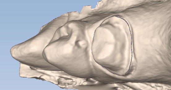 Fig. 10.4Irregularities in the adjacent tooth will cause problems with cementation and ultimately the contact
10.2.2 A Few Pointers on Milled Restorations
-
When using all-ceramic restorations from the laboratory or your own milling unit, one must understand the dimensions of the burs that create your restoration. Careful and thoughtful preparation of teeth is essential when using milled restorations (Figs. 10.5 and 10.6).
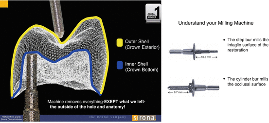 Fig. 10.5CEREC milling units
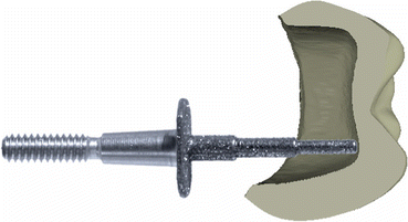 Fig. 10.6The depth of the preparation should never exceed the length of the bur
 -
Margins should be smooth and continuous. The burs and software cannot mill sharp edges! Open margins are a result of roughness that is ignored around the margins.
-
Ensure preparation shoulders; incisal edges or cusp tips are at least 1.3 mm in diameter to allow for proper milling (Fig. 10.7).
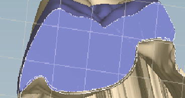 Fig. 10.7Cross section shows a thin margin. This may lead to the material fracturing during milling. Followed by an open margin in the restoration
 -
Respect the diameter of the milling bur. Avoid sharp edges along your preparation as these may result in improper milling causing the restoration not to seat.
-
Undercuts in the preparation walls will not be milled by the software. This creates a larger gap between the restoration and the tooth surface that will be filled with cement. Use of your software’s mill preview allows you to view these undesirable areas (Fig. 10.8a,b).
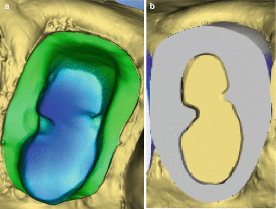 Fig. 10.8(a) Undercuts should be blocked or removed from the preparation. (b) This cross-sectional view with the restoration shows gaps between the tooth and the milled restoration
 -
Undercuts in interproximal area should be avoided; the machine will mill these area’s causing the restoration not to seat (Fig. 10.9).
 Fig. 10.9Undercuts in the interproximal boxes prevent a path of draw. Line shows where the preparation should end in order to have a path of draw
10.3 The CAD/CAM Workflow
10.3.1 Scanning
-
Prior to scanning, proper isolation of the tooth and visibility of the preparation margins are essential. Occlusal clearance should be checked prior to scanning and can be measured accurately after scanning. Scanning is the final impression and all the old traditional rules apply: use of packing cord, hemostatic agents, or use of a laser/electro surgery to facilitate visualization of the margins.
-
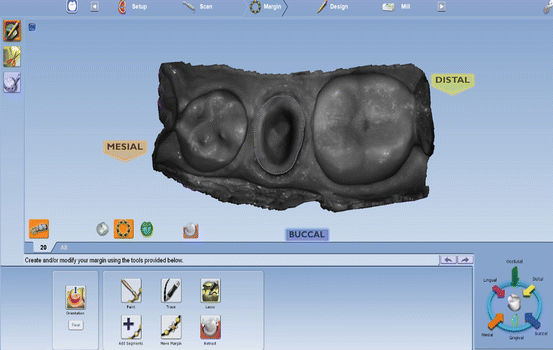
The scanned prepared tooth is the perfect opportunity to critique your own work! It is a good time to check if the preparation exhibits a path of draw. Check for undercuts, occlusal clearance, and sharp edges. The contour on adjacent teeth can prevent visualization of the entire tooth from the occlusal view. Corrections must be made, and rescan of the preparation, if necessary, prior to continuing onto the design phase (Fig. 10.10).
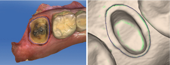 Fig. 10.10Sirona’s CEREC and Planmeca’s E4D scan of the preparation
 -
For more information on scanning, see chapter on “Digital Impressions.”
10.3.2 Design and Milling