Fig. 2.1
Drawing from USP 3,925,892
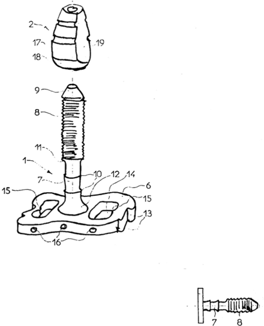
Fig. 2.2
Implant design by Dr. Clunet-Coste, France
Clunet-Coste, by the way, would initially buy his own implants in Italy to avoid paying his own licence fees. Scortecci, in turn, acquired his Swiss-made implants via Monaco. Zerca discontinued this production line a year after Julliet’s death in September 1983. Around the same time, Scortecci entered the market with his cutters and rotationally symmetrical designs named “Diskimplant®”. It appears that these developments held great appeal for Clunet-Coste himself because he allowed Scortecci to continue producing and marketing his products without a licence (F.P. Spahn, personal communication, 2001). Anyway, taking out patents on manufacturing processes only in specific European countries is no longer meaningful these days. As a matter of fact, patents on manufacturing techniques are likely to become pointless even if confined to Europe in this era of increasingly global markets and cheap manufacturing sites in the countries of the former East Block.
Three further patents taken out by Scortecci in the USA (1987, 1988) and in Europe (1985) added another chapter to the history of disk implantology.
In his U.S. patent, Scortecci described an implant that served as its own insertion tool. The patent also covers some aspects of the lateral insertion process.
The idea was to design an implant surface that included cutter flutes and to remove the turbine after the bone concavity had been cut, thereby leaving the implant well anchored inside the bone. The turbines available then and today have a chuck diameter of 1.6 mm, which was a limiting factor for the diameter of the implant shaft (i.e. the threaded pin). Consequently, this design routinely led to implant fractures. The system as described in the patent has never been widely marketed.
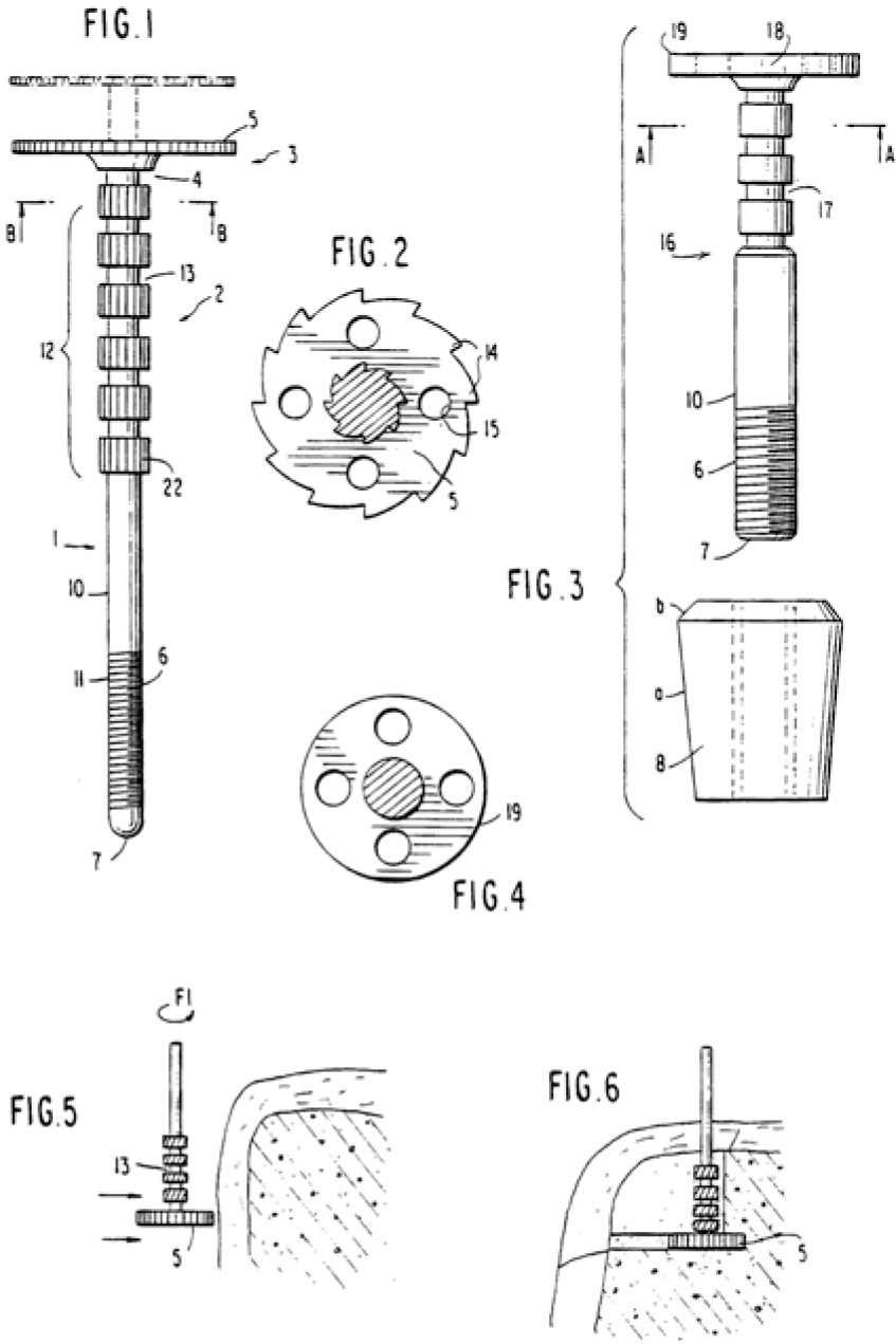
Fig. 2.3
Drawing from USP 4,722,687
Figure 2.4 illustrates the lateral insertion path; Scortecci envisioned a system in which the size and shape of the implant bed did not necessarily coincide with the implant design.
Item 8 in Fig. 2.5 shows that the osteotomy path was longer than the implant. This approach presupposes that the cortical bone structure in the mandible is adequately wide. It is necessary to remember that functional alterations associated with the restorative treatment or hormonal changes may lead to massive endosteal resorption. If so, the chances are that the implant will recede in lingual or vestibular direction into the newly evolving cancellous bone areas. This problem has been eliminated in the asymmetrical implant designs, which are discussed below.
The U.S. patents were granted without problems at the time. The procedure went not so smoothly in Europe, where the patent specification had to be revised. Meanwhile, Scortecci had been collecting experience by using his implant designs in practice, so there was time to amend the original patent claims to reflect this experience by the time the European patent was eventually granted. The U.S. patents, by contrast, were granted almost unmodified.
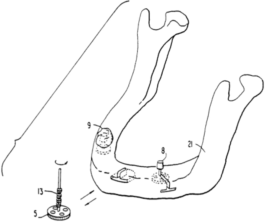
Fig. 2.4
Drawing from USP 4,722,687 and USP 4,815,974
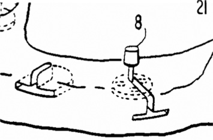
Fig. 2.5
Enlarged section of Fig. 2.4
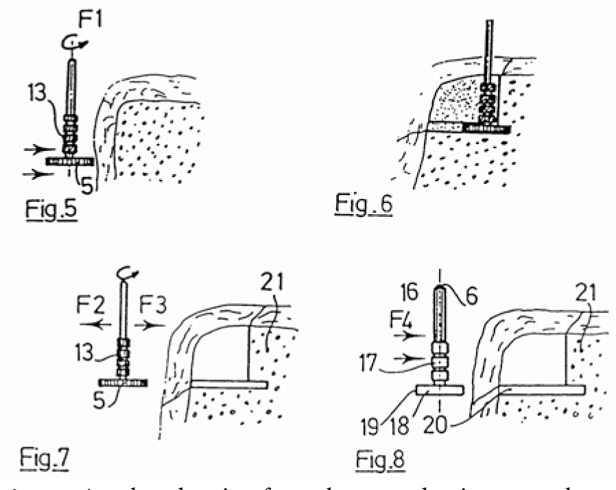
Fig. 2.6
Another drawing from those productive years shows that Scortecci envisioned the use of small rings along the shaft serving as force-transmitting surfaces and depth indicators. The implant itself also featured rings of this type. The advantage of this configuration was that it gave the surgeon a very accurate idea how long the implant needed to be. On the downside, it involved an additional risk of mucosal and bone irritation in the presence of elastic implant-restoration systems
Despite these developments, the resources that were funnelled into the universities for the teaching of dental implantology were invariably distributed in favour of screw implants. Industry was expecting a faster turnaround in revenues from screw implants and reasoned that the insertion techniques could be explained more readily to dentists than the procedure for blade and disk implants. Also, the risks to the prosthetic work seemed smaller if only those screw implants that were found to be intact after a healing period of 3–6 months could be fitted with a tailor-made superstructure.
In other words, the concept of immediate loading associated with the BOI system entailed the requirement that all inserted implants had to be clinically successful. Since any implant failure automatically leads to loss of the superstructure, there is always a risk of financial consequences to the dentist. While BOI went through a phase of inexcusable neglect for these reasons, a flurry of adjuvant procedures for bone augmentation/grafting emerged on the scene. This development may have been a blessing for some – particularly for maxillofacial surgeons – but it has improved neither the actual success nor the theoretical potential of implant treatment.
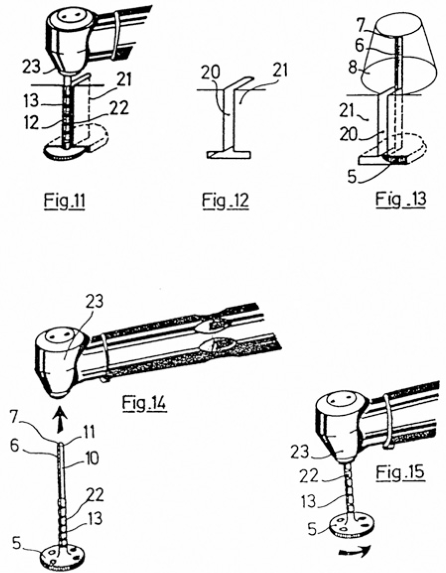
Fig. 2.7
Drawings from EP 0 241 962 B1. These sketches illustrate in detail the insertion procedure generating the implant bed. The vertical and horizontal dimension of the insertion path were obtained simultaneously by using a specially designed cutter
An essential feature of this design was that implants and tools were separated. Scortecci’s patent lawyers deserve considerable respect for the fact that they succeeded, by resourceful phrasing, in incorporating as subclaim 6 the exact opposite of the original idea of the patent application, such that it escaped the reviewers’ notice and formed part of the patent granted.
In 1991, Scortecci published a retrospective study on the clinical outcomes of his Diskimplant system (Scortecci et al. 2001). In the years 1979–1989, a total of 5,848 implants had been inserted, 590 of which had to be removed. Most of these implant losses occurred in the period 1980–1984, presumably either because the disk diameters were too small or because the threaded pins were too short. Another factor was that the original disks were not perforated at all; the next generation featured perforations that were still very small. Fractures resulting from the small diameter of the threaded pins (a consequence of adhering to the U.S. patent specification and the 1.6 mm shaft diameter) also contributed to some failures. Not with standing, a cumulative success rate of almost 90% over a 10-year period was a remarkable feat, considering that similar figures were also reported for screw and blade implants at the time. With Scortecci’s development of standardized cutters for implant beds, lateral implantology ultimately became an option even in the hands of less skilful surgeons. Therefore Scortecci is rightly to be regarded as one of the “founding fathers” of lateral implantology.
In his comprehensive book on dental implantology, published in 2001, Scortecci laid out a large number of treatment options with disk implants. He combined disk implants with “structure” screw implants, mainly for screwed bridges. His multiple implant concept based on 8–14 implants in each arch was associated with huge material requirements and enormous costs. In addition, it turned out that the bone structures would stiffen as a result of this approach. By the same token, today’s implants do not feature surface enlargement to avoid irritation of the surrounding bone. As a consequence, individual implants that are embedded in elastic bone segments may turn out to be mobile when bridges are removed. This type of mobility does not have any clinical or radiographic implications. Considering the implant/restoration system as a whole, these mobile implants still constitute a stable basis for the restoration.
Other fellow dentists have also contributed ideas to the development that eventually led to basal osseointegration. The Belgian dentist Robert Streel (1980), for instance, was the first to describe bendable lateral implants. Streel postulated that implant treatment must try to achieve a perfect balance of forces. This demand is not plausible from today’s perspective; after all, the bone structure in which the force-transmitting areas are embedded are not uniformly protected against resorption, either.
Areas 5 and 8 in Fig. 2.8 are the bendable lateral stubs.
The fact that disks at the implant base can be used in a completely different manner had been demonstrated by Christensen as early as in 1965. The caudal insertion path of this design has remained somewhat of an obstacle. Dentists are not accustomed to this type of surgical approach.
For the same reason, the transmandibular implant (TMI) design, although offering extremely good results in the treatment of mandibular resorption, has never been too popular among dentists. A handful of fellow dentists well versed in surgical techniques have used these implant very successfully for decades. Numerous patients have thankfully recovered their masticatory function in this way.
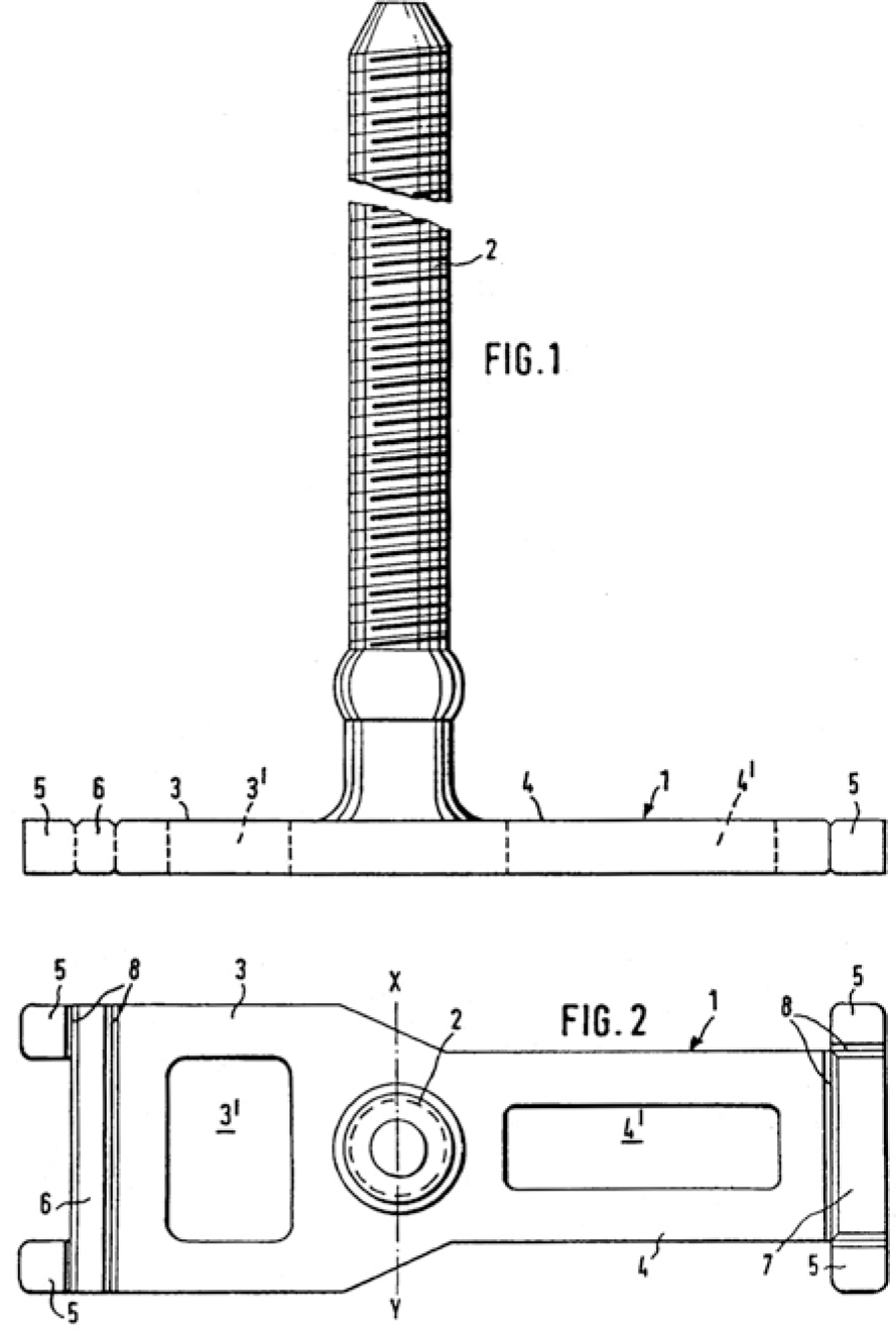
Fig. 2.8
“Perfectly balanced” disk implant with bendable lateral stubs that are intended to ensure primary stability to lateral forces. In other words, part of the design will be locked up in a subperiosteal position. This concept of basal osseointegration has survived to this day
The TMI system has a lot in common with today’s BOI system:
-
The implants have no load transmission either near areas where the implant penetrates the mucosa or in the vertical implant portion.
-
All load transmission takes place in areas that are safe from infection.
-
Load transmission is multicortical.
Another innovative mind influencing the development of dental implants was Albert Kurtis. The design he specified in his patent of 1988 was aimed at anchoring the threaded pin deep inside the bone to endow the implant shaft with resilience and room for flexural manoeuvre while preventing infections from advancing to the load-transmitting implant segments. At that time, features such as round struts for load deflection and round framework transitions to avoid load peaks were remarkable achievements in structural design. The blood supply in the insertion area would probably remain largely intact with this design.
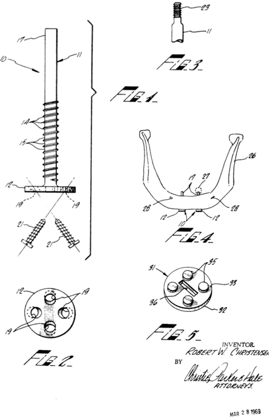
Fig. 2.9
From USP 3,474,537. Christensen’s implant design relied on a caudal insertion path. The disk was not inserted into an enossal position but was covered by caudal bone growth in due course
Another name to be mentioned in this context is Alfred Edelmann, whose U.S. patent specification (1978) also included (albeit as a minor point) basal solutions for his implant design.
Stay updated, free dental videos. Join our Telegram channel

VIDEdental - Online dental courses


