Chapter 2
General Parameters of Medical Space Planninga
BUILDING SHELL DESIGN
Efficient medical offices begin with an intelligently designed building shell. All too often, medical office buildings (MOBs) are planned by designers or architects who are unfamiliar with the special requirements of medical tenants; thus, the structure of the building does not lend itself to an efficient layout of suites. Structural column locations, stair placement, elevators, electrical rooms, mechanical shafts, public restrooms, and window modules either impede or facilitate layout of individual suites. The importance of an efficient shell and core design upon the interior space planning cannot be stressed enough.
Other factors that influence the design of an MOB are the shape and size of the site, the specific requirements of a particular tenant or client, a beautiful view, accessibility, site utilities, solar orientation, parking requirements, and the architect’s desire to impose a unique design on the project. All of these factors have to be weighed and balanced along with applicable codes, height and zoning restrictions, and the budget. A building that is completely functional and efficient, but totally insensitive to aesthetics may not lease as quickly as the owners may wish. But an MOB designed primarily for aesthetic merit, with only secondary concern for internal planning efficiency, will also be difficult to lease.
Another important factor in the design of an MOB is the exterior skin of the building. Whether the windows are part of a curtain wall or in a bearing wall affects the openness of the exterior wall and how much daylight is coming in. The spacing of the mullions is critical not only in the vertical direction but also in the horizontal. For example, the sill height should be no lower than the height of a typical countertop plus backsplash, and the header should not be higher than the typical ceiling height. The spacing of the mullions is also critical to interior layouts and efficiencies.
Floor Area Efficiency
To begin with, an MOB should contain at least 12,000 square feet of rentable space per floor in order to accommodate suites of varying sizes and configurations as well as to increase the efficiency of stairs and elevators. Larger buildings often have 20,000 square feet or more per floor. The elevators, elevator lobby, mechanical equipment room, electrical room, telephone room, lab pickup box storage room, and public restrooms can be placed in the core with rental space wrapped around the perimeter (Figure 2-1) or the services may be located at the ends of a double-loaded public corridor (Figure 2-2). Figure 2-3 gives 89 percent rentable space, but it lacks public restrooms. Medical buildings are usually designed to 85 percent efficiency, but architectural features such as an atrium or a large lobby can reduce the efficiency to 80 percent.
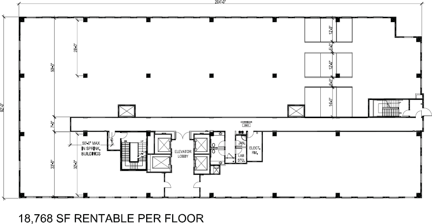
Figure 2-1. Floor plan, building shell, depicts a 33-foot deep bay for smaller suites and a 50-foot deep bay for larger suites, providing maximum flexibility. Locations of stairs and core services allow for a very large suite to wrap across the end of the building.
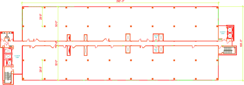
Figure 2-2. Floor plan, building shell, depicts a large building footprint with both sides of the building offering a 50-foot bay depth that puts smaller suites at a disadvantage as they will be narrow and with little natural light reaching the core of the space.
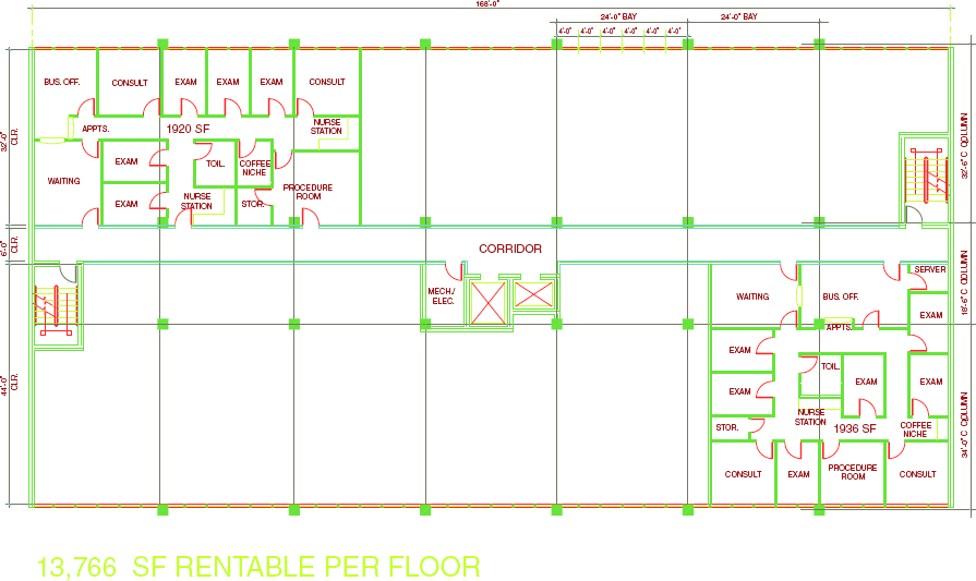
Figure 2-3. Floor plan, building shell, offers an example of how the same suite, built in two different bay depths, can yield significant differences in access to natural light, flow, and even the number of exam rooms.
The core factor is 12 percent in Figure 2-2, reflecting the gain in efficiency due to the large floor plate that is designed to accommodate large users on the 50-foot-bay-depth side. If the building is leased to smaller tenants, public corridors penetrating the 50-foot depth may have to be added, thereby reducing somewhat the potential usable area.
Special attention must be paid to location of stairwells when one tenant intends to lease an entire floor or half a floor. In such a case, the public exit stairwell may fall within an individual suite—a nonpublic space. One way to handle this is to provide a third stair in the center of the building so that, even if one tenant takes half a floor, two stairs remain accessible for tenants on the other half of the floor (Figure 2-4).
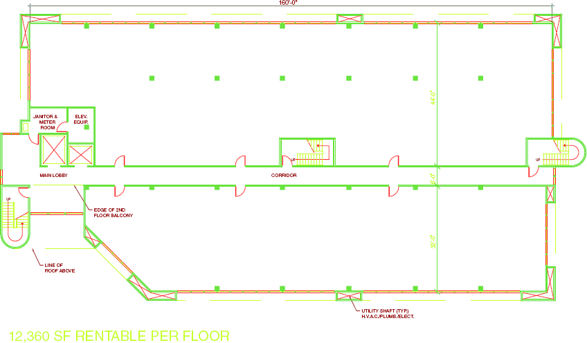
Figure 2-4. Floor plan, building shell, shows a small building footprint that accommodates both small and large suites. The placement of stairs provides access to two exits even if one tenant leases half of the building, running across the 82-foot width.
Figure 2-1 shows a layout with one stair set in to allow a large suite to run across the end of the building at 92 feet, using a 50-foot “allowable” dead-end corridor, extending from the stairwell. One must remember, however, when locating a suite across the end of a building: If the occupancy load is high enough, two exits may be required, with a separation equal to one-third the distance of the longest diagonal of the suite in a building equipped throughout with an automatic sprinkler system. In a large suite, this would be achieved by extending another corridor perpendicular to the public corridor for the secondary exit.
In spite of these issues, especially with a floor plate as large as that shown in Figure 2-1, setting in the stair on one end provides great flexibility with respect to the size of suites that may be accommodated. It should be noted that the stairwells themselves must be located with a minimum separation equal to one-third the distance of the longest diagonal of the building floor plate measured along the shortest path of travel within the corridor if the building is equipped throughout with an automatic sprinkler system.
Structural Support
The structural support system for the building should allow as much flexibility as possible for the layout of tenant spaces. For a multistory building, a moment-resistant steel frame offers considerably more flexibility in space planning and window placement than does a building supported with diagonal or “K” braces, for example. Of course, moment-resistant steel frame connections are a considerably more expensive option. An additional consideration in the selection of the structural system is the tenant’s perspective. In using the national BOMA (ANSI Z65.1) standards for measuring buildings, tenants pay for the “wasted” space above and below diagonal bracing. Tenants will use this as a bargaining chip and present the lessor with a challenge in maintaining cordial tenant relationships. Regardless of the type of structural system used, it is imperative that the structural engineer work very closely with the medical space planner, so that structural elements can be accommodated within the planning grid.
Perimeter columns, ideally, would be flush with the inside face of the exterior wall (Figure 2-3) so that they do not protrude into the building or room and, at the very least, are flush with the exterior face of the building so that protrusion into the building or room is minimized. On the interior, columns for a 32-foot bay depth would fall as shown in Figure 2-3 on the inside face of the public corridor wall, spanning 32 feet 6 inches center to center, creating a column-free space in between.
For a 50-foot bay depth, the intermediate column should occur at 30 feet on center, measured from the column on the exterior wall, and depending upon whether it is flush with the exterior face or extends totally from the inside of the exterior wall (Figures 2-1 and 2-2). Here, there will be a 12-foot-deep row of rooms across the exterior wall and then a 5-foot-wide hallway, followed by another row of 12-foot-deep rooms, then another 5-foot-wide hallway and a row of 14-foot-deep rooms adjacent to the common area corridor. The column should fall inside a room creating a flush wall in the hallway, as shown in the lower diagram of Figure 2-5.
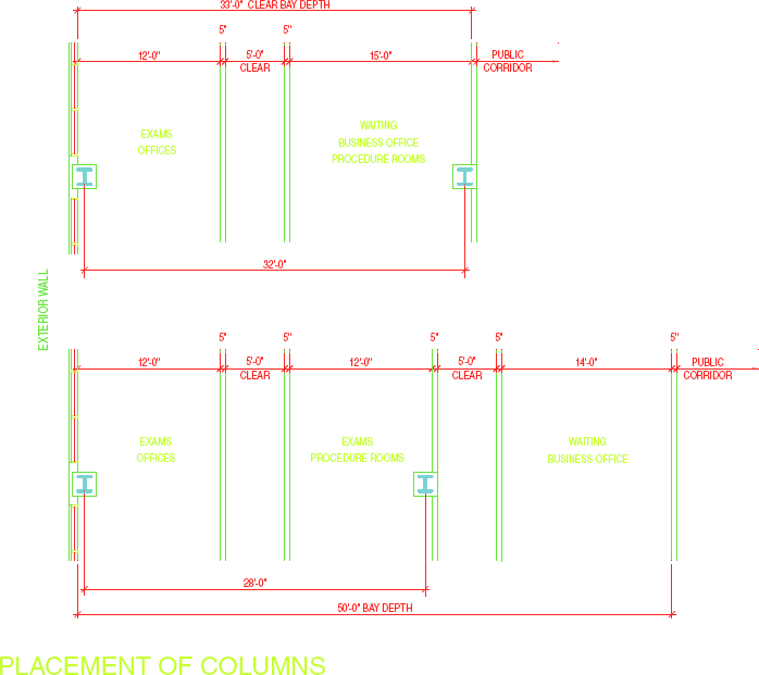
Figure 2-5. Placement of columns.
Another option for locating the intermediate column in a 44-foot-bay depth is illustrated in Figure 2-3. It occurs in the wall of the business office or waiting room, making it 34 feet on center, measured from the column on the exterior wall.
It is difficult to give absolute dimensions for locating columns, because there are so many variables: the “box-in” size of the columns; utilities running along columns, including roof drains and sewer lines; and the fact that high-rise buildings have larger columns, all affect the spacing between them.
Locations of structural columns should not adversely affect the flexibility of the space if the building is engineered properly. Most rooms are small thus the density of partitions is high. Long spans are not necessary but a tradeoff inevitably arises here. Reducing the span between columns makes it possible to use lighter-weight and shorter beams, thereby reducing the cost of the building and reducing the height. However, more columns, closer together, reduce space-planning flexibility. The occurrence of perimeter columns at intervals, creating 24-foot-wide or 32-foot-wide bays, and interior columns spaced as shown in Figure 2-4, often works well. Where the bay depths on both sides of the corridor are 32 feet, all columns may be contained in the perimeter walls, with none occurring within tenant spaces.
PLANNING MODULE
A considerable amount of standardization exists in the sizes of rooms in a medical suite. For the most part, suites can be laid out on a 4-foot planning grid. However, one must acknowledge the odd-sized treatment rooms, toilets, and specialty rooms such as radiology. The 4-foot planning module accommodates the traditional 8 × 12–foot exam room and the larger 10 × 12–foot exam room that is becoming the new standard for reasons explained in Chapter 3.
Stay updated, free dental videos. Join our Telegram channel
VIDEdental - Online dental courses


