Introduction
Our objective was to evaluate the factors that affect effective torque control during en-masse incisor and canine retraction when using partially osseointegrated C-implants (Cimplant, Seoul, Korea) as the exclusive source of anchorage without posterior bonded or banded appliances.
Methods
Base models were constructed from a dental study model. No brackets or bands were placed on the maxillary posterior dentition during retraction. The working archwire was modeled by using a 3-dimensional beam element (ANSYS beam 4, Swanson Analysis System, Canonsburg, Pa) with a cross section of 0.016 × 0.022-in stainless steel. Different heights of anterior retraction hooks and different degrees of gable bends were applied to the working utility archwire that was placed into the 0.8-mm diameter hole of the C-implant to generate anterior torque on the anterior segment of the teeth. The amount of tooth displacement after finite element analysis was exaggerated 70 times and compared with tooth-axis graphs of the central and lateral incisors and the canine.
Results
The height of the anterior retraction hook and the degree of the gable bend had a combined effect on the labial crown torque applied to the incisors during en-masse retraction. By using 30° gable bends and the longest hook, lingual root movement of the 6 anterior teeth occurred. By using 20° gable bends, the 6 anterior teeth showed a translation tendency during retraction.
Conclusions
Three-dimensional en-masse retraction of the 6 anterior teeth can be accomplished by using partially osseointegrated C-implants as the only source of anchorage, gable bends, and a long retraction hook (biocreative therapy type I technique).
After Kanomi’s report on this concept, published case reports with mini-implants when applying conventional orthodontic mechanics have shown new complications, such as anterior bite deepening, occlusal plane canting, and posterior open bite or posterior crossbite. When using mini-implants to retract the anterior teeth, it is most important to consider the location of the center of resistance (CR) relative to the location of the mini-implants. Successful bodily translation of the anterior teeth might require additional complicated archwires or a supplementary mini-implant in the anterior segment. If bilateral mini-implants are not in the same horizontal plane, as sometimes required by the anatomy of the maxilla, the clinician could see unwanted canting of the occlusal plane because of the different vectors of forces during retraction. A final concern is that sliding mechanics in a full-arch appliance with mini-implant-assisted anterior retraction might be adversely affected by friction in the bracket slots and tubes.
In recent reports, a new treatment system has been described, called biocreative therapy ( C-therapy ), to implement independent en-masse retraction of the anterior teeth while avoiding orthodontic appliances on the posterior segments during the retraction period. This concept developed because partially osseointegrated mini-implants or plates can easily endure multidirectional heavy forces even when they support orthodontic archwires. In C-therapy, it is possible to retract the anterior segment independently by directly placing the wire into the hole of the mini-implant. This mini-implant system allows light continuous forces, the ability to control complex tooth movements, minimum friction, and no need for patient compliance.
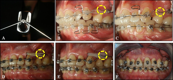
In the cited clinical study, mini-implants were used as the only source of anchorage for en-masse retraction of the 6 maxillary anterior teeth. No appliances were placed in the maxillary and mandibular posterior dentition. The mini-implants were designed to accommodate archwires that were free to slide during retraction and could resist the force levels necessary for a wide range of applications. Since applied orthodontic forces during anterior retraction are against the mini-implants and not against the orthodontic appliances fixed to the posterior teeth, no change in the posterior occlusion is expected during retraction. This beneficial protocol is only possible if the mini-implant does not loosen in response to the heavy or dynamic forces that would be necessary. The C-implant (sand-blasted, large-grit, acid-etched mini-implant; Cimplant, Seoul, Korea) allows the application of a gable bend in the buccal area that will apply a moment to the mini-implant, but not loosen the screw. This gable bend produces forces that control the torque and the vertical position of the incisor segment. The bend is easily applied with an Omega loop-forming pliers ( Fig 1 ). To date, there are no reviews regarding the factors involved in control of anterior torque by this technique except clinical literature and case reports. In this study, we constructed a 3-dimensional (3D) finite element model of the maxillary teeth, periodontal ligament (PDL), and alveolar bone after extracting the first premolars. After placing orthodontic mini-implants with an 0.8-mm hole at 8 mm above the expected bracket position between the second premolar and the first molar, we applied a utility archwire to the 6 anterior teeth and placed the posterior ends of the archwire into the holes of the mini-implants, effectively using the mini-implant as a posterior orthodontic tube. We simulated the effect on torque control using different heights of retraction hooks located between the lateral incisor and the canine, and different angles of gable bends on the archwire.
Material and methods
We obtained the tooth outline forms by 3D laser scanning of a maxillary right tooth from a dental study model (base model) (model-i21D-400G; Nissin Dental Products, Kyoto, Japan) of an adult with normal occlusion. Using the Micro-arch bracket (Tomy, Tokyo, Japan), we aligned and leveled with a broad arch form (Ormco, Glendora, Calif) and referred to the studies of Andrews, Germane et al, and Park and Yang for inclinations and angulations. We did not add a curve of Spee or a curve of Wilson ( Fig 2 , A ).
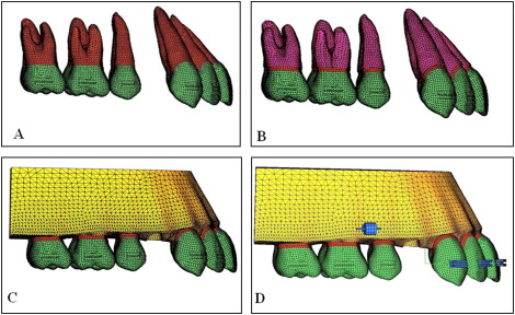
The thickness of the PDL was assumed to be uniform (0.25 mm) according to the studies of Coolidge and Kronfeld ( Fig 2 , B ). The alveolar bone crest was constructed to follow the curvature of the cementoenamel junction 1 mm apical to it. The 3D finite element model included 12 teeth, open space according to the missing first premolars, periodontal space, and alveolar bone, and was bilaterally symmetrical ( Fig 2 , C ). In the base model, the distance from the incisal edge of the maxillary central incisor to the bracket slot (perpendicular to the occlusal plane) was 4.5 mm, 11 mm to the labial cementoenamel junction, and 11.8 mm to the labial alveolar crest. In the finite element model, teeth, alveolar bones, brackets, periodontal spaces, C-implant, and archwire were constructed with fine tetrahedron solid elements; the tooth and bracket were connected without interference, and each tooth contacted the next at the contact point as individual elements ( Fig 2 , D ). In this study, teeth, alveolar bones, and periodontal spaces were assumed to be isoparametric and homogeneous linear elastic bodies, and the material properties of the elements were Young’s modulus and Poisson’s ratio according to the studies of Tanne et al, Ziegler et al, and Poppe et al ( Table I ). In the system studies, we construct the x-axis as the in-out direction, the y-axis as the labiolingual direction, and the z-axis as the upper-lower direction, and defined +x as the left central incisor direction, +y as the labial direction, +z as the apical direction, and the x-y plane as the occlusal plane of the teeth ( Fig 3 , A and B ).
| Young’s modulus (MPa) | Poisson’s ratio | |
|---|---|---|
| PDL | 5.0E-02 | 0.49 |
| Alveolar bone | 2.0E ± 03 | 0.30 |
| Teeth | 2.0E ± 04 | 0.30 |
| Stainless steel | 2.0E ± 05 | 0.30 |
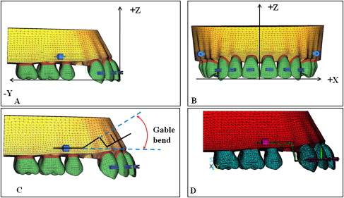
The archwire was modeled by using a 3D beam element (ANSYS beam 4, Swanson Analysis System, Canonsburg, Pa) with a cross section of 0.016 × 0.022-in stainless steel. The archwire hook (0.019 × 0.025-in stainless steel) was set at the midpoint between the lateral incisor bracket and the canine bracket bilaterally ( Fig 3 ). The gable bend was located at the posterior third of the space of the extracted maxillary first premolar, activated toward the root (+z), and placed with bends of 0°, 10°, 20°, 30°, and 40° ( Fig 3 , C and D ). The osseointegration-based C-implant, which has a 0.8-mm diameter hole on the head part, was placed 8 mm above the expected bracket position between the second premolar and the first molar.
For convenience of analysis, we assumed that there were no gaps between the bracket and the archwire at the right maxillary central and lateral incisors and canine, and carried out the nonlinear analysis, allowing the gap element between the archwire and the 0.8-mm diameter hole of C-implant head. The retraction force was 150 g between the anterior retraction hook (ARH) and the C-implant head, the lengths of hooks were 4 mm (short), 7 mm (standard), and 10 mm (long), and the angles of the gable bends were 0°, 10°, 20°, 30°, and 40°. The tooth displacements were marked by applying the x, y, and z coordinates at the midpoints of the incisal edges of the 2 incisors, the cusp tip of the canine, and each tooth’s root apex.
For the finite element analysis, ANSYS 11 (Swanson Analysis System), which is the universal finite element program, was used on a workstation (XW6400; Hewlett-Packard, Palo Alto, Calif).
Results
The tooth-displacement pattern on the z-axis is shown in Table II and Figures 4 and 5 .
| Tooth | Hook length | Gable bend | |||||
|---|---|---|---|---|---|---|---|
| 0° | 10° | 20° | 30° | 40° | |||
| Right maxillary central incisor | 4 mm | Root apex | 3.31E-02 | 3.22E-02 | 3.12E-02 | 3.03E-02 | 3.07E-02 |
| Incisal edge | −2.18E-02 | −1.77E-02 | −1.35E-02 | −9.36E-03 | −5.79E-03 | ||
| 7 mm | Root apex | 3.48E-02 | 3.39E-02 | 3.31E-02 | 3.20E-02 | 3.09E-02 | |
| Incisal edge | −3.84E-03 | 3.46E-04 | 4.35E-03 | 8.61E-03 | 1.29E-02 | ||
| 10 mm | Root apex | 3.61E-02 | 3.52E-02 | 3.43E-02 | 3.34E-02 | 3.23E-02 | |
| Incsal edge | 1.42E-02 | 1.84E-02 | 2.25E-02 | 2.66E-02 | 3.09E-02 | ||
| Right maxillary lateral incisor | 4 mm | Root apex | 1.72E-02 | 1.69E-02 | 1.67E-02 | 1.65E-02 | 1.62E-02 |
| Incisal edge | −1.90E-02 | −6.32E-03 | 6.34E-03 | 1.88E-02 | 2.99E-02 | ||
| 7 mm | Root apex | 1.41E-02 | 1.39E-02 | 1.35E-02 | 1.34E-02 | 1.33E-02 | |
| Incisal edge | −8.94E-03 | 3.67E-03 | 1.64E-02 | 2.90E-02 | 4.16E-02 | ||
| 10 mm | Root apex | 1.08E-02 | 1.06E-02 | 1.03E-02 | 1.01E-02 | 9.93E-03 | |
| Incisal edge | 1.26E-03 | 1.39E-02 | 2.65E-02 | 3.92E-02 | 5.18E-02 | ||
| Right maxillary canine | 4 mm | Root apex | 1.55E-02 | 1.40E-02 | 1.24E-02 | 1.08E-02 | 8.77E-03 |
| Incisal edge | −3.09E-02 | −7.70E-03 | 1.56E-02 | 3.90E-02 | 6.30E-02 | ||
| 7 mm | Root apex | 6.78E-03 | 5.23E-03 | 3.75E-03 | 2.21E-03 | 6.64E-04 | |
| Incisal edge | −4.45E-02 | −2.13E-02 | 1.95E-03 | 2.53E-02 | 4.86E-02 | ||
| 10 mm | Root apex | −2.02E-03 | −3.58E-03 | −5.09E-03 | −6.60E-03 | −8.14E-03 | |
| Incisal edge | −5.76E-02 | −3.44E-02 | −1.11E-02 | 1.21E-02 | 3.55E-02 | ||
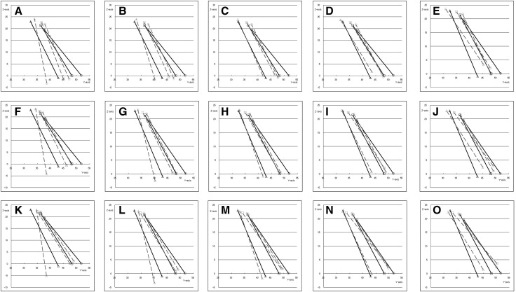
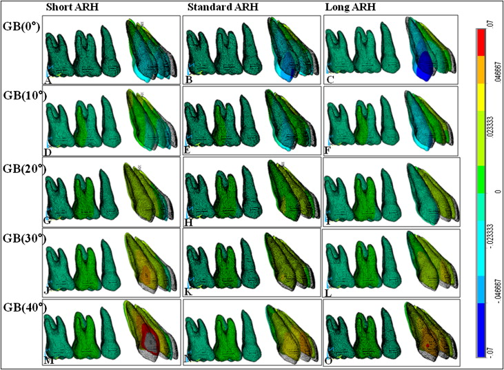
In applying the 150-g orthodontic force between the ARH and the C-implant head if the gable bend was 0°, the canine experienced the most extrusion because of the step-down bend of the main archwire (0.016 × 0.022-in). By using a midsized hook, an increase in the gable bend decreased the amount of extrusion of all teeth (right maxillary incisors and canine), and eventually all anterior teeth intruded with a gable bend greater than 20°.
With an increase of the length of the ARH, the amounts of extrusion of the incisors decreased. So even without a gable bend, intrusion occurred with the long hook ( Fig 4 , A , F , and K ). However, without a gable bend, the amount of extrusion of the canine increased as the length of the ARH increased.
The tooth-displacement pattern in the y-axis is shown in Table III and Figure 6 .
| Tooth | Hook length | Gable bend | |||||
|---|---|---|---|---|---|---|---|
| 0° | 10° | 20° | 30° | 40° | |||
| Right maxillary central incisor | 4 mm | Root apex | 2.57E-03 | 9.49E-04 | −8.37E-04 | −2.87E-03 | −4.81E-03 |
| Incisal edge | −6.62E-02 | −6.22E-02 | −.81E-02 | −5.42E-02 | −5.24E-02 | ||
| 7 mm | Root apex | −9.08E-03 | −1.10E-02 | −1.24E-02 | −1.44E-02 | −1.65E-02 | |
| Incisal edge | −5.37E-02 | −4.97E-02 | −4.57E-02 | −4.15E-02 | −3.73E-02 | ||
| 10 mm | Root apex | −2.07E-02 | −2.26E-02 | −2.42E-02 | −2.59E-02 | −2.79E-02 | |
| Incisal edge | −4.05E-02 | −3.65E-02 | −3.25E-02 | −2.84E-02 | −2.42E-02 | ||
| Right maxillary lateral incisor | 4 mm | Root apex | 5.29E-03 | −1.09E-03 | −7.37E-03 | −1.34E-02 | −1.86E-02 |
| Incisal edge | −4.58E-02 | −3.54E-02 | −2.51E-02 | −1.48E-02 | −5.27E-03 | ||
| 7 mm | Root apex | −5.82E-03 | −1.20E-02 | −1.85E-02 | −2.46E-02 | −3.07E-02 | |
| Incisal edge | −2.85E-02 | −1.82E-02 | −7.80E-03 | 2.50E-03 | 1.28E-02 | ||
| 10 mm | Root apex | −1.69E-02 | −2.30E-02 | −2.94E-02 | −3.58E-02 | −4.19E-02 | |
| Incisal edge | −1.09E-02 | −5.92E-04 | 9.79E-03 | 2.02E-02 | 3.05E-02 | ||
| Right maxillary canine | 4 mm | Root apex | 2.15E-02 | 1.03E-02 | −8.40E-04 | −1.20E-02 | −2.34E-02 |
| Incisal edge | −6.30E-02 | −3.96E-02 | −1.62E-02 | 7.40E-03 | 3.19E-02 | ||
| 7 mm | Root apex | 2.75E-02 | 1.64E-02 | 5.23E-03 | −5.95E-03 | −1.71E-02 | |
| Incisal edge | −6.43E-02 | −4.08E-02 | −1.75E-02 | 6.00E-03 | 2.95E-02 | ||
| 10 mm | Root apex | 3.33E-02 | 2.21E-02 | 1.10E-02 | −2.01E-04 | −1.14E-02 | |
| Incisal edge | −6.47E-02 | −4.13E-02 | −1.79E-02 | 5.52E-03 | 2.90E-02 | ||
Stay updated, free dental videos. Join our Telegram channel
VIDEdental - Online dental courses


