Introduction
The purpose of this study was to evaluate the effects of a newly designed magnetic palatal expansion appliance with a reactivation system.
Methods
A magnetic palatal expansion appliance was designed based on the repulsion forces of neodymium-iron-boron magnets combined with a reactivation system. Eighteen prepubertal male beagle dogs were assigned randomly to the magnetic expansion (ME) group, the mechanical screw expansion (SE) group, or the control group. Two pairs of nonmagnetic metal bone marker implants were inserted into palatal bone bilaterally 3 mm lateral to the midpalatal suture and in line with the first and fourth premolars, respectively, in each dog. The 6 animals in each group received (1) newly designed magnetic expanders, (2) jackscrew expanders, or (3) no expansion appliance. Expansion was stopped after 4 weeks when 6 mm of activation was achieved in the 2 treated groups. Three-dimensional evaluations of dental and skeletal effects were performed with cone-beam computed tomography. Histologic examinations were conducted using light microscopy to observe morphologic changes in the midpalatal suture after hematoxylin and eosin staining.
Results
The absolute transversal changes of both treated groups before and after expansion were significantly greater than those in the control group in all parameters ( P <0.001). The differences of the distances of bilateral canines in the ME group were significantly greater than in the SE group (1.04 ± 0.16 mm; P <0.001); the differences of the distances between implants adjacent to the first premolars (0.77 ± 0.06 mm; P <0.001) and the distances between implants adjacent to the fourth premolars (0.37 ± 0.06 mm; P <0.001) in the SE group were significantly greater than in the ME group. Histologic observations of the palatal sutures in the ME and SE groups, when compared with the control group, showed widening of the sutures and many fibroblasts in an active, proliferative state. Counts of osteoblasts were increased in both expansion groups. Counts of osteoclasts were increased in the SE group.
Conclusions
Both appliances expanded the maxilla effectively and induced processes of bone remodeling of the midpalatal sutures during expansion. The new magnetic palatal expansion appliances produced a smaller skeletal effect and a greater dental effect than did the mechanical screw palatal expansion appliances.
Highlights
- •
We designed a magnetic palatal expansion appliance with a reactivation system.
- •
We examined the effects of the magnetic palatal expansion appliance in dogs.
- •
The magnetic appliance expanded the maxilla effectively.
- •
It also stimulated reconstruction of the midpalatal suture during expansion.
Palatal expansion is often used to increase the transverse width of the maxillary arch aimed to correct a constricted maxilla and eliminate crowding. Magnetic force, a viable alternative to traditional force systems, has been used in palatal expansion since the 1980s based on its characteristics of providing forces of sufficient intensity and duration independent of patient cooperation, appropriate force vector control, and atraumatic periodontal remodeling.
Although animal experiments and clinical studies have confirmed the feasibility of magnetic palatal expansion, several shortcomings have limited its widespread use. Early-generation magnets possessed a relatively small magnetic energy product and produced insufficient magnetic forces; thus, large size and mass were required to provide sufficient expansion force, resulting in poor patient comfort and oral hygiene. This limitation was overcome with the development of the third generation of “high-energy” rare-earth permanent magnetic alloy neodymium-iron-boron magnets. These magnets can produce high forces and demonstrate notable improvements in the maximum energy product, allowing for a dramatic reduction in the size of magnets required to produce a given magnetic flux. Additionally, these new high-energy magnets have high coercivity (a measure of the ability of a magnetic material to withstand an external magnetic field without becoming demagnetized) that improves their application in palatal expansion.
High-energy magnets have shown strong potential for clinical applications as a palatal expansion device, but long-term clinical application has been limited by the corrosion tendencies of magnets in the oral cavity. Furthermore, concerns have been raised about the possible cytotoxicity of the corrosion products and the biologic consequences for oral tissues. To prevent corrosion of magnets in the oral environment, the authors of earlier studies attempted to seal the magnets in acrylic or with stainless steel covers. Recently, in-vitro studies have demonstrated that a diamond-like carbon coating can enhance resistance to corrosion and reduce the cytotoxicity of the neodymium-iron-boron magnets, permitting long-term safe use in the oral cavity.
A second problem of magnetic palatal expanders is that the force produced between 2 magnets diminishes dramatically with distance, potentially making the expansion force unstable. For a more continuous force, researchers have attempted to reactivate magnetic expansion appliances by adding synthetic fluorine-containing rings, screws, or magnetic blocks until the gap between the magnetic poles was reclosed to maintain sufficient forces, but the clinical operation was complicated and not friendly to oral hygiene.
To overcome the aforementioned problem, in this study a new type of magnetic palatal expansion appliance was designed based on the repulsion forces of neodymium-iron-boron magnets coated with diamond-like carbon and combined with a reactivation system to overcome the limitation of decreasing magnetic force with distance. Effects of the expander were evaluated in animal experiments and observed by cone-beam computed tomography (CBCT) and histologic examination to provide reference data for future basic research and clinical applications.
Material and methods
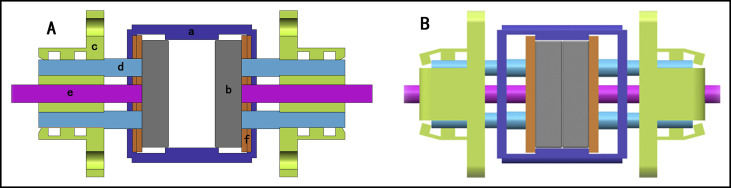
High-energy neodymium-iron-boron magnets were selected and coated with diamond-like carbon. The magnetic palatal expansion appliances were designed based on the repulsion force with a reactivation system. A schematic diagram of the magnetic palatal expansion appliances is shown in Figure 1 . The force/distance for each magnetic palatal expansion appliance was determined using a universal testing machine (2343; Instron, Canton, Mass).
All animal work was performed using protocols approved by the Institutional Animal Care and Use Committee of the Medical College of Nanchang University in China. The sample consisted of 18 male beagle dogs aged 6 months (comparable in maturation to human age of 9-11 years) and weighting 8 kg. The animals were sedated with 2% pentobarbital sodium (1 mL/kg, intraperitoneally). After we drilled pilot holes in the palatal bone at low speed, we inserted 2 pairs of nonmagnetic metal bone marker implants (diameter, 0.7 mm; length, 5 mm) bilaterally about 3 mm lateral to the palatal suture and in line with the first and fourth premolars, respectively. The dogs were assigned randomly to 3 groups, with 6 dogs in the magnetic expansion (ME) group receiving the newly designed magnetic expanders, 6 dogs in the mechanical screw expansion (SE) group receiving jackscrew expanders, and 6 dogs in the control group having no expander but housed under the same conditions as the other animals.
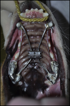
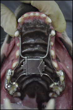
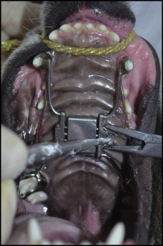
Palatal expansion appliances were customized for each animal by casting individual bands for the maxillary canines, fourth premolars, and first molars. The bands were connected to the screw expanders or to the pushing plates of the magnetic expanders, where the expander mechanism was placed at the center of a quadrilateral formed by the bilateral canine cusp tips and mesiobuccal cusp tips of the first molar ( Figs 2 and 3 ). During appliance fabrication, the pushing plates were fully compressed and maintained in position temporarily with ligature wires. The animals were anesthetized, and the palatal expansion appliances were cemented to the abutment teeth; then the ligature wires were removed. Because the dogs needed to be anesthetized during each reactivation, considering the uncertain influence of anesthesia on the expansion effect, growth, and safety, the frequency of activation was reduced relative to daily activation that is often used in clinical practice. Instead, the expanders in the SE group were activated twice per week, 0.75 mm per activation, whereas the expanders in the ME group were loaded once at the beginning of treatment and once after 2 weeks when nearly 3 mm of expansion was achieved. Three millimeters of reactivation of the magnetic expanders was achieved by the following steps: first, the distance between the 2 magnets was zeroed out by squeezing the central release links; and second, the position was clamped by crimping the weak point of the limiting grooves of the pushing plate ( Fig 4 ). The expansion was complete after 4 weeks when 6 mm of activation had been achieved in both treated groups.
CBCT images were acquired at the Affiliated Stomatological Hospital of Nanchang University at baseline (T1) and immediately after removing the expanders when expansion was achieved (T2) with a 3D eXam CBCT scanner (KaVo Dental, Biberach, Germany). During scanning, the heads of the dogs were positioned in a customized plastic jig. The scanning parameters were 120 kVp, 20.27 mAs, and 14.7 seconds per revolution, with a pixel size of 0.25 mm. The reconstruction interval was 16 × 16 × 10 cm. All operations were performed by the same technician. The CBCT images were then saved as digital imaging and communications in medicine (DICOM) files and reconstructed into 3D volumes using InVivo software (version 5.1.10; Anatomage, San Jose, Calif).
To improve the reliability of the measurement data, calibrations were made by reorienting the skull images in the 3 dimensions into the same standardized position using the InVivo dental software according to the method of Guijarro-Martinez and Swennen.
- 1.
Axial plane ( Fig 5 , A ). The axial plane was determined by a plane through the highest point of the upper margin of the bilateral infraorbital foramen (red points in Fig 5 , B and C ) and the left porion ( green point in Fig 5 , C ).
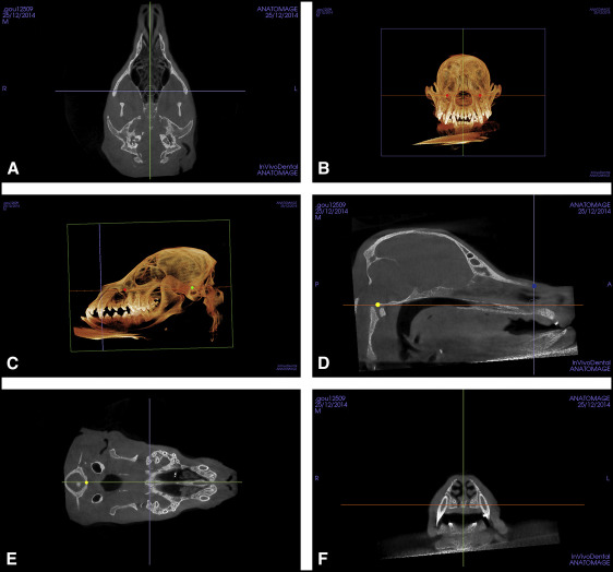
Fig 5 Determination of the axial, midsagittal, and coronal planes: A, axial plane; B, location of the highest point of the upper margin of bilateral infraorbital foramen; C, location of the highest point of the upper margin of left porion; D, location of the center of the ANS and the front margin of the occipital condyle in the midsagittal plane; E, location of the center of the front margin of the occipital condyle in the axial plane; F, coronal plane ( red point , highest point of the upper margin of infraorbital foramen; green point , highest point of the upper margin of left porion; yellow point , center of the front margin of the occipital condyle; blue point , center of the ANS). - 2.
Midsagittal plane ( Fig 5 , D ). The midsagittal plane was perpendicular to the axial plane. It was fixed by a plane through the center of the anterior nasal spine (ANS) ( blue points in Fig 5 , D ) and the front margin of the foramen magnum ( yellow points in Fig 5 , D and E ). When a bifid ANS was encountered in the frontal view, the midsagittal plane was established at the midpoint between the 2 bony prominences.
- 3.
Coronal plane ( Fig 5 , F ). The coronal plane was perpendicular to the axial and sagittal planes and through the center of the ANS.
We measured the following parameters.
- 1.
Distance between the bilateral canines: measured between the cusp tip of the bilateral maxillary canines in 2-dimensional (2D) coronal images through the cusp tips of the left canines ( Fig 6 , A ).
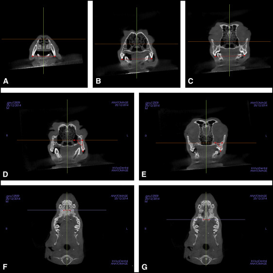
Fig 6 Measurements made from CBCT images: A, distance between bilateral canines; B, distance between bilateral fourth premolars; C, distance between bilateral first molars; D, angulation of the fourth premolar; E, angulation of the first molar; F, distance between bone marker implants adjacent to the fourth premolar; G, distance between bone marker implants adjacent to the first molar. - 2.
Distances between the bilateral fourth premolars and first molars: measured between the mesiobuccal cusp tip of bilateral teeth in the 2D coronal images through the mesiobuccal cusp tip of left fourth premolar or first molar ( Fig 6 , B and C ).
- 3.
Angulations of the fourth premolar and first molar: measure of the angles formed by the long axis of the fourth premolar or first molar (from cusp tips to apices) and the axial plane in the 2D coronal images through the distal apices of the fourth premolar or first molar. Bilateral angulations of the fourth premolar and first molar were determined, and the mean value was obtained ( Fig 6 , D and E ).
- 4.
Distances between implants adjacent to the first premolar: the distance between implants measured in the 2D axial images through the central cervical part (connection interface of bone) of the left implant ( Fig 6 , F ).
- 5.
Distances between implants adjacent to the fourth premolar: the distance between implants measured in the 2D axial images through the central cervical part (junction interface of bone) of the left implant ( Fig 6 , G ).
All measurements were performed 3 times by 1 examiner (J.L.) under the same conditions, and the measurements were averaged. Intraexaminer reliability was within ± 5% for all measurements as determined by data replications at least 2 weeks apart.
The dogs were killed using intravenous injection of pentobarbital (10 mg/kg) under anesthesia after 4 weeks. After the CBCT imaging, specimens from the maxillae, 15 × 15 mm, were dissected centered on the midpalatal suture and midway between the first premolar and the first molar. The specimens were fixed in formalin (10% formaldehyde) solution for 24 hours, demineralized in Plank-Rychlo’s decalcifying fluid for 1 week, dehydrated through an ascending ethanol series, cleared in xylene, and embedded in paraffin. Coronal histologic sections were cut with a microtome at 4 μm and stained with hematoxylin and eosin. Three serial sections from the center of the tissue sample to the frontal direction were selected to undergo the histologic examinations.
Histologic examinations were conducted using a light microscope (BX 41; Olympus, Tokyo, Japan) equipped with a controller (DP 3.2.276.2; Olympus) and a manager (DP 3.1.1.208: Olympus) and reviewed by 2 pathologists. After examination, a photograph of each slide was taken using a digital camera (DP 71; Olympus).
From the 3 animal groups, osteoblasts and osteoclasts were counted using magnification of 400 times, coupled with a 100-div reticle eyepiece with 10 × 10 μm squares (Olympus, Tokyo, Japan). Cell counts were made by a pathologist viewing along the transition line between bone and suture; they were immediately counted again by a second pathologist, blinded to the first evaluation. Histologic evaluations were performed by using a semiquantitative method based on known normal characteristics of cells within the palatal suture where osteoblasts, osteoclasts, and fibroblasts could be delineated by their cytologic characteristics. Osteoblasts were arranged on the surface of bone, and the nuclei were large, spherical, and darkly stained. An active osteoblast was also characterized morphologically by prominent cell processes connected with the adjacent osteoblasts and osteocytes. Osteoclasts were characterized as large multinucleated cells. Fibroblasts had 2 states, including an activated state and a less active state. Inactive fibroblasts, also called fibrocytes, were smaller and spindle shaped, whereas active fibroblasts were larger and round.
Statistical analysis
All statistical analyses were performed using SPSS software (version 19.0; IBM, Armonk, NY). The consistency or reproducibility of cell counting made by different observers was assessed by intraclass correlation coefficient (ICC) analysis. For each variable measured on the CBCT images and the counts of cells, the mean and standard deviation were calculated. Paired t tests were used to determine the statistical significance of differences between T1 and T2. Differences in all CBCT measurements and the counts of osteoblasts and osteoclasts between the ME, SE, and control groups were assessed for significance by using 1-way analysis of variance (ANOVA; P = 0.05).
Results
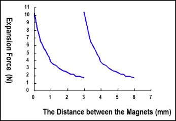
The force-deflection curves after 2 force loadings up to distances of 3 mm were similar, indicating that the mechanical properties of the magnetic palatal expansion appliances after the first activation and the reactivation were largely the same ( Fig 7 ). Between 0 and 3 mm of separation, the force range varied by 10.38 to 1.63 N, respectively.
Of the initial 18 beagles for which CBCT scans were analyzed, 1 in the SE group and 2 in the control group died of anesthesia overdose during the first CBCT scanning. The rest of the dogs in the treated groups successfully completed the maxillary expansion and were included in the analysis. The dogs in the treated groups showed no abnormal changes in diet, activity, psychosis, and body weight after receiving the expansion appliance.
The maxillary transverse dimensions of all parameters showed significant increases after expansion in the treated groups. In the control group, there were also significant increases in all parameters with the exception of the inclination of the fourth premolar from T1 to T2. Table I summarizes the comparison of absolute transverse changes (T2-T1) in the 3 groups; statistically significant differences were detected. Comparisons of measurement changes among the 3 groups are shown in Table II . Both treated groups differed significantly from the control group in all parameters. When we compared the 2 treatment groups, differences in the distance between bilateral canines in the ME group were significantly greater than in the SE group, and differences in the distances between the bilateral first and fourth premolars in the SE group were significantly greater than in the ME group.
| Measurement | Group | n | Mean | SD | F | P |
|---|---|---|---|---|---|---|
| Difference of DC (mm) | SE | 5 | 5.21 | 0.22 | 568.611 | 0.000 |
| ME | 6 | 6.25 | 0.34 | |||
| Control | 4 | 0.75 | 0.12 | |||
| Difference of DPM4 (mm) | SE | 5 | 4.41 | 0.41 | 150.194 | 0.000 |
| ME | 6 | 4.56 | 0.47 | |||
| Control | 4 | 0.53 | 0.14 | |||
| Difference of DM1 (mm) | SE | 5 | 3.81 | 0.47 | 40.023 | 0.000 |
| ME | 6 | 3.63 | 0.29 | |||
| Control | 4 | 1.22 | 0.70 | |||
| Difference of APM4 (°) | SE | 5 | 4.92 | 0.57 | 127.629 | 0.000 |
| ME | 6 | 4.63 | 0.51 | |||
| Control | 4 | −0.69 | 0.72 | |||
| Difference of AM1 (°) | SE | 5 | 5.76 | 1.08 | 50.899 | 0.000 |
| ME | 6 | 4.94 | 0.90 | |||
| Control | 4 | 0.35 | 0.15 | |||
| Difference of DIPM1 (mm) | SE | 5 | 2.49 | 0.17 | 620.987 | 0.000 |
| ME | 6 | 1.72 | 0.06 | |||
| Control | 4 | 0.07 | 0.01 | |||
| Difference of DIPM4 (mm) | SE | 5 | 1.67 | 0.17 | 296.335 | 0.000 |
| ME | 6 | 1.30 | 0.04 | |||
| Control | 4 | 0.05 | 0.02 |
Stay updated, free dental videos. Join our Telegram channel
VIDEdental - Online dental courses


