Introduction
The aim of this study was to analyze stress distribution and displacement of the craniofacial structures resulting from bone-borne rapid maxillary expanders with and without surgical assistance using finite element analysis.
Methods
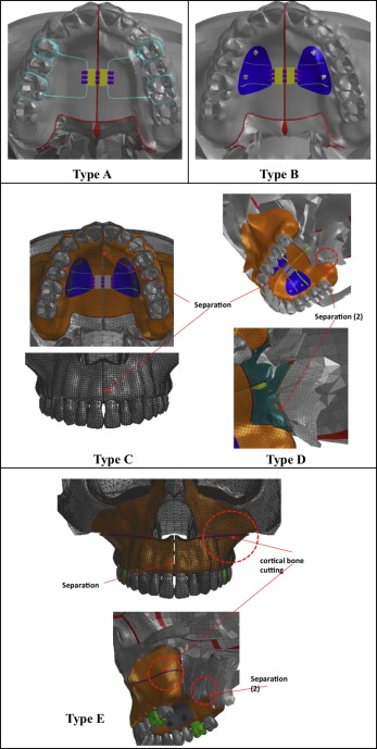
Five designs of rapid maxillary expanders were made: a tooth-borne hyrax expander (type A); a bone-borne expander (type B); and 3 bone-borne surgically assisted modalities: separation of the midpalatal suture (type C), added separation of the pterygomaxillary sutures (type D), and added LeFort I corticotomy (type E). The geometric nonlinear theory was applied to evaluate the Von Mises stress distribution and displacement.
Results
The surgical types C, D, and E demonstrated more transverse movement than did the nonsurgical types A and B. The amounts of expansion were greater in the posterior teeth in types A and B, but in types C, D, and E, the amounts of expansion were greater in the anterior teeth. At the midpalatal suture, the nonsurgical types showed more anterior expansion than did the posterior region, and higher stresses than with the surgical types. Type B showed the highest stresses at the infraorbital margin, anterior and posterior nasal spines, maxillary tuberosity, and pterygoid plate and hamulus.
Conclusions
The 3 surgical models showed similar amounts of stress and displacement along the teeth, midpalatal sutures, and craniofacial sutures. Therefore, when using a bone-borne rapid maxillary expander in an adult, it is recommended to assist it with midpalatal suture separation, which requires minimal surgical intervention.
For decades, rapid maxillary expansion (RME) has been 1 treatment option for the correction of transverse maxillary deficiency and arch length discrepancy. In adults, nonsurgical palatal expansion can result in dentoalveolar tipping that might consequently cause unfavorable periodontal effects. Therefore, skeletal orthopedic expansion is essential to prevent such effects and to establish proper posterior occlusion.
Traditionally, surgically assisted RME has been the treatment of choice for adults to overcome their interdigitated midpalatal suture and decreased elasticity of bone, but this method produces only minimal horizontal translation and was mainly a lateral rotation of the 2 maxillary halves. In addition, Byloff and Mossaz demonstrated a large amount of relapse during the postretention period; however, other studies have shown mean relapse amounts of less than 1 mm. Gauthier et al reported radiographic changes that might have a detrimental clinical impact on the periodontium.
Han et al showed that a combination of LeFort I and paramedian osteotomies with pterygomaxillary separation is an effective procedure for increasing the expansion of the maxilla with fewer side effects caused by excessive stress around the anchor teeth. However, the amount of distortion with this method at the craniofacial sutures has not been evaluated. Neither have the effects of temporary skeletal anchorage devices (TSADs) for transverse expansion been evaluated.
Recently, TSADs have been applied to correct this transverse problem. Lee et al reported a case with miniscrews in the paramedian area for a bone-borne rapid maxillary expander connected to the teeth. Kim and Helmkamp showed various designs of rapid maxillary expanders with miniscrews. Garib et al applied palatal implants to support RME. Also, Lagravère et al assessed the effect of a bone-borne RME appliance with palatal slope anchors. Nada et al evaluated the long-term effects of tooth-borne and bone-borne surgically assisted RME using cone-beam computed tomography. The treatment effects of RME have been extensively studied through various methods, including analysis of photoelastic models, laser holography, and 3-dimensional (3D) finite element (FE) models.
The stress distribution and displacement resulting from the application of various designs of bone-borne palatal expanders were reported in a 3D analysis. Also, Boryor et al evaluated bone-borne RME on a cadaver using FE analysis and reported opening the midpalatal suture.
Although clinical studies have provided useful findings, a precise evaluation of the biomechanical effects of orthopedic forces on the internal bony structures, including the sutures of the craniofacial complex, has been limited. Furthermore, no study has evaluated the effects of bone-borne RME on the whole craniofacial structure and compared it with various surgically assisted modalities.
Therefore, the aim of this in-vitro study was to analyze stress distribution and displacement of the craniofacial structures resulting from bone-borne RME with and without surgical assistance using 3D FE analysis to improve our understanding of the mechanics of these treatment modalities.
Material and methods
For the finite element model, a computer-aided design model was constructed from a computed tomography scan of a dry skull of an adult using MIMICS software (version 15.01; Materialise, Leuven, Belgium). The geometry of this anatomic model was imported using Visual-mesh software (version 7.0; ESI Group, Paris, France) to generate a tetrahedral FE mesh.
The FE model was sectioned, with the maxilla including the teeth and alveolar bone sectioned into 1-mm tetrahedrons, and the rest of the skull excluding the maxilla sectioned into 5-mm tetrahedrons. The teeth, alveolar bone, and periodontal ligament were considered to be homogenous and isotropic. Previously reported material properties of each component are shown in Table I .
| Young’s modulus (MPa) | Poisson’s ratio | |
|---|---|---|
| Cortical bone | 13700 | 0.30 |
| Cancellous bone | 1370 | 0.30 |
| Enamel | 80350 | 0.33 |
| Dentin | 19890 | 0.31 |
| Peridodontal ligament | 50 | 0.49 |
| Titanium | 113000 | 0.33 |
| Resin | 2000 | 0.30 |
The thickness of the cortical bone was determined according to the study by Farnsworth et al ; the thickness of the periodontal ligament was 0.2 mm, and the thicknesses of the maxillofacial and midpalatal sutures were 0.5 mm.
The foramen magnum was completely fixed and used as the origin point, as suggested by Gautam et al. The 3D coordinates were X, sagittal plane; Y, transverse plane; and Z, vertical plane.
An expansion screw that widened by 0.25 mm per turn and 4 C-implants (Cimplant, Seoul, Korea) of 1.8 mm in diameter and 8.5 mm in length were used. There were 5 designs of rapid maxillary expanders: a conventional tooth-borne hyrax expander (type A), a bone-borne expander (type B), and 3 bone-borne expanders consisting of type B combined with 3 surgical designs (types C, D, and E). In type B, 4 C-implants were placed 8 mm beneath the alveolar ridge at the palatal slope: 2 between the canines and the first premolars, and 2 between the second premolars and the first molars. Then, the C-implants were connected to the expander through an acrylic resin cover, as in the study of Lee et al. In type C, the appliance was assisted by surgical separation of the midpalatal suture. In type D, the surgery included surgical separation of the midpalatal and pterygomaxillary sutures. In type E, a corticotomy extending from the piriform aperture to the maxillary tuberosity (LeFort I corticotomy) was added to type D ( Fig 1 ).
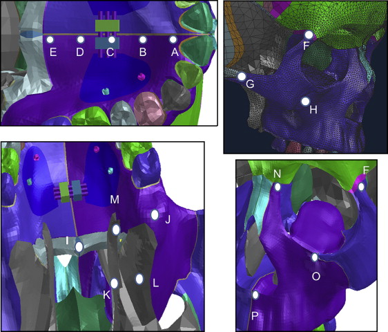
Expanders were activated transversely by 0.5 mm in the Y direction but were unfixed in the X and Z directions to prevent interference with the resultant movement. For the FE analysis, the following software programs were used: Visual-mesh version 7.0 for meshing, PAM-MEDYSA version 2011 for solving, and Visual-Viewer version 7.0 for postprocessing (ESI Group). Following the study of Lee et al, we applied the geometric nonlinear theory and implicit method for analysis. Von Mises stress distribution and displacement at the maxillofacial region were evaluated ( Fig 2 ). The midpoint of the lingual alveolar ridge of each tooth was used as a reference point to evaluate alveolar bone displacement. Positive values indicate forward, outward, and upward displacement on the X, Y, and Z planes, respectively.
Results
In the transverse plane, the amounts of alveolar bone displacement in types A and B were greater in the posterior than in the anterior areas. Types C, D, and E showed larger amounts of transverse expansion compared with types A and B, but more in the anterior area than in the posterior. Sagittally, in types A and B, the alveolar bone at the anterior area showed backward movement, whereas at the posterior it moved slightly forward. Vertically, in type A, the alveolar bone at all teeth was extruded more in the anterior than in the posterior area. However, in type B, it was intruded. Types C, D, and E showed rotation of the occlusal plane where the anterior area was extruded and the posterior was intruded ( Table II ).
| Lingual marginal ridge of alveolar bone | Type A | Type B | Type C | Type D | Type E | ||||||||||
|---|---|---|---|---|---|---|---|---|---|---|---|---|---|---|---|
| X | Y | Z | X | Y | Z | X | Y | Z | X | Y | Z | X | Y | Z | |
| Central incisor | −0.072 | 0.063 | −0.076 | −0.057 | 0.064 | −0.020 | 0.021 | 0.296 | −0.053 | 0.007 | 0.285 | −0.055 | 0.007 | 0.286 | −0.056 |
| Lateral incisor | −0.047 | 0.082 | −0.052 | −0.026 | 0.082 | 0.005 | 0.012 | 0.294 | −0.026 | 0.005 | 0.285 | −0.027 | 0.005 | 0.286 | −0.027 |
| Canine | −0.024 | 0.108 | −0.033 | −0.001 | 0.105 | 0.021 | 0.006 | 0.284 | −0.006 | 0.003 | 0.277 | −0.006 | 0.003 | 0.278 | −0.006 |
| First premolar | 0.019 | 0.164 | −0.003 | 0.021 | 0.156 | 0.041 | 0.002 | 0.268 | 0.005 | 0.001 | 0.266 | 0.006 | 0.001 | 0.266 | 0.006 |
| Second premolar | 0.015 | 0.164 | −0.009 | 0.025 | 0.186 | 0.033 | −0.001 | 0.261 | 0.013 | 0.000 | 0.263 | 0.013 | 0.000 | 0.264 | 0.013 |
| First molar | 0.021 | 0.181 | −0.009 | 0.019 | 0.185 | 0.025 | −0.005 | 0.240 | 0.020 | −0.003 | 0.251 | 0.021 | −0.003 | 0.251 | 0.021 |
| Second molar | 0.012 | 0.127 | −0.007 | 0.012 | 0.134 | 0.031 | −0.011 | 0.209 | 0.029 | −0.007 | 0.232 | 0.032 | −0.007 | 0.232 | 0.032 |
Transversally, types A and B showed opening of the midpalatal suture, with the maximum amount at the anterior area. The surgically assisted models demonstrated greater displacements but less difference between the anterior and posterior areas. In the sagittal direction, types A and B showed backward movement of all midpalatal suture points, with a gradual decrease from the anterior to the posterior areas. Type C showed a uniform amount of forward displacement throughout the suture. Vertically, all types had downward movement of the midpalatal suture ( Table III ).
| Type A | Type B | Type C | Type D | Type E | |||||||||||
|---|---|---|---|---|---|---|---|---|---|---|---|---|---|---|---|
| X | Y | Z | X | Y | Z | X | Y | Z | X | Y | Z | X | Y | Z | |
| Point A | −0.052 | 0.049 | −0.084 | −0.078 | 0.052 | −0.040 | 0.026 | 0.276 | −0.072 | 0.008 | 0.265 | −0.076 | 0.008 | 0.266 | −0.077 |
| Point B | −0.022 | 0.040 | −0.090 | −0.047 | 0.044 | −0.048 | 0.025 | 0.222 | −0.074 | 0.007 | 0.216 | −0.078 | 0.007 | 0.216 | −0.079 |
| Point C | −0.012 | 0.035 | −0.096 | −0.028 | 0.034 | −0.051 | 0.026 | 0.191 | −0.076 | 0.007 | 0.194 | −0.079 | 0.007 | 0.193 | −0.080 |
| Point D | −0.005 | 0.017 | −0.068 | −0.019 | 0.029 | −0.050 | 0.026 | 0.169 | −0.078 | 0.007 | 0.181 | −0.082 | 0.007 | 0.180 | −0.083 |
| Point E | −0.005 | 0.017 | −0.068 | −0.011 | 0.018 | −0.045 | 0.026 | 0.145 | −0.081 | 0.007 | 0.168 | −0.084 | 0.006 | 0.170 | −0.084 |
Transversely, in types C, D, and E, all points showed outward displacement of the craniofacial sutures except for the frontomaxillary suture in the 3 types and the maxillary tuberosity in type E, where there was minimal medial movement. However, types A and B showed smaller amounts of displacement compared with types C, D, and E. The infraorbital margin, the anterior nasal spine, and the frontomaxillary suture showed medial movement. Sagittally, all displacements were minimal in all models. Vertically, in all types, the anterior and posterior nasal spines showed downward displacement. In type A, the zygomaticomaxillary suture, the pterygoid hamulus, and the medial and lateral pterygoid plates were displaced downward ( Table IV ).
| Type A | Type B | Type C | Type D | Type E | |||||||||||
|---|---|---|---|---|---|---|---|---|---|---|---|---|---|---|---|
| X | Y | Z | X | Y | Z | X | Y | Z | X | Y | Z | X | Y | Z | |
| Frontomaxillary suture | 0.003 | −0.014 | −0.014 | −0.021 | −0.022 | 0.041 | −0.002 | −0.003 | −0.006 | −0.002 | −0.008 | −0.007 | −0.003 | −0.009 | −0.006 |
| Zygomaticomaxillary suture | −0.085 | 0.041 | −0.090 | 0.010 | 0.005 | 0.109 | −0.045 | 0.115 | 0.122 | −0.018 | 0.110 | 0.129 | −0.018 | 0.107 | 0.127 |
| Frontozygomatic suture | −0.007 | 0.005 | 0.020 | −0.025 | 0.000 | 0.071 | −0.033 | 0.015 | 0.068 | −0.031 | 0.016 | 0.068 | −0.031 | 0.016 | 0.067 |
| Zygomatic arch | 0.005 | 0.014 | 0.007 | −0.003 | −0.014 | 0.035 | −0.012 | 0.122 | 0.072 | −0.009 | 0.096 | 0.060 | −0.009 | 0.094 | 0.059 |
| Pterygoid hamulus | 0.001 | 0.049 | −0.024 | −0.003 | 0.057 | 0.007 | −0.001 | 0.130 | 0.003 | −0.004 | 0.166 | 0.005 | −0.004 | 0.166 | 0.005 |
| Medial pterygoid plate | −0.001 | 0.014 | −0.009 | −0.005 | 0.014 | 0.020 | 0.005 | 0.035 | 0.001 | 0.001 | 0.012 | 0.007 | 0.001 | 0.012 | 0.008 |
| Lateral pterygoid plate | 0.004 | 0.019 | −0.002 | 0.003 | 0.021 | 0.029 | 0.005 | 0.041 | 0.017 | 0.000 | 0.012 | 0.012 | 0.000 | 0.012 | 0.012 |
| Maxillary tuberosity | 0.002 | 0.090 | 0.028 | 0.009 | 0.093 | 0.066 | −0.028 | 0.159 | 0.070 | −0.014 | 0.197 | 0.075 | −0.014 | 0.207 | 0.075 |
| Infraorbital margin | 0.007 | −0.022 | 0.027 | 0.000 | −0.038 | 0.084 | −0.031 | 0.084 | 0.081 | −0.014 | 0.069 | 0.085 | −0.014 | 0.074 | 0.086 |
| Posterior nasal spine | 0.002 | 0.001 | −0.046 | −0.009 | 0.002 | −0.018 | 0.023 | 0.130 | −0.066 | 0.006 | 0.162 | −0.070 | 0.006 | 0.162 | −0.070 |
| Anterior nasal spine | −0.034 | −0.008 | −0.098 | −0.051 | −0.018 | −0.033 | 0.021 | 0.205 | −0.065 | 0.004 | 0.182 | −0.068 | 0.004 | 0.181 | −0.069 |
At the midpalatal suture, type B showed higher stresses than did type A, which in turn had higher stresses than did types C, D, and E. The highest stresses in types C, D, and E were at the frontomaxillary, zygomaticomaxillary, and frontozygomatic sutures. In type A, the highest stress was at the zygomaticomaxillary suture. Type C showed higher stresses in the pterygoid area and the zygomatic arch compared with types D and E ( Table V ; Figs 3-8 ).
| Type A | Type B | Type C | Type D | Type E | |
|---|---|---|---|---|---|
| Midpalatal suture landmarks | |||||
| Point A | 28.370 | 57.170 | 0.469 | 0.519 | 0.489 |
| Point B | 25.830 | 124.000 | 2.621 | 2.007 | 1.779 |
| Point C | 12.820 | 132.300 | 3.124 | 1.565 | 1.402 |
| Point D | 17.280 | 77.660 | 1.756 | 0.577 | 0.514 |
| Point E | 17.280 | 73.110 | 0.685 | 0.436 | 0.549 |
| Maxillofacial landmarks | |||||
| Frontomaxillary suture | 4.232 | 10.200 | 13.960 | 13.330 | 12.780 |
| Frontozygomatic suture | 1.137 | 3.310 | 8.238 | 8.662 | 8.522 |
| Infraorbital margin | 4.885 | 9.916 | 0.835 | 1.427 | 1.485 |
| Zygomaticomaxillary suture | 24.600 | 11.240 | 10.310 | 9.834 | 9.296 |
| Zygomatic arch | 0.628 | 1.196 | 5.061 | 3.666 | 3.595 |
| Anterior nasal spine | 3.931 | 20.350 | 0.066 | 0.055 | 0.062 |
| Posterior nasal spine | 7.470 | 27.870 | 0.093 | 0.068 | 0.075 |
| Medial pterygoid plate | 1.130 | 5.554 | 5.712 | 0.061 | 0.060 |
| Lateral pterygoid plate | 1.514 | 7.245 | 6.472 | 0.036 | 0.036 |
| Pterygoid hamulus | 6.785 | 21.910 | 9.327 | 1.709 | 1.789 |
| Maxillary tuberosity | 3.363 | 10.010 | 1.346 | 0.663 | 0.609 |
Stay updated, free dental videos. Join our Telegram channel
VIDEdental - Online dental courses


